EP0051094A1 - Appareil pour la mesure de liquides - Google Patents
Appareil pour la mesure de liquides Download PDFInfo
- Publication number
- EP0051094A1 EP0051094A1 EP80303905A EP80303905A EP0051094A1 EP 0051094 A1 EP0051094 A1 EP 0051094A1 EP 80303905 A EP80303905 A EP 80303905A EP 80303905 A EP80303905 A EP 80303905A EP 0051094 A1 EP0051094 A1 EP 0051094A1
- Authority
- EP
- European Patent Office
- Prior art keywords
- tube
- liquid
- valve means
- piston
- outlet
- Prior art date
- Legal status (The legal status is an assumption and is not a legal conclusion. Google has not performed a legal analysis and makes no representation as to the accuracy of the status listed.)
- Withdrawn
Links
- 239000007788 liquid Substances 0.000 title claims abstract description 54
- 235000013361 beverage Nutrition 0.000 claims abstract description 13
- 230000000694 effects Effects 0.000 claims abstract description 8
- XLYOFNOQVPJJNP-UHFFFAOYSA-N water Substances O XLYOFNOQVPJJNP-UHFFFAOYSA-N 0.000 claims description 6
- 230000000977 initiatory effect Effects 0.000 claims description 2
- 229920003023 plastic Polymers 0.000 abstract description 3
- 239000004033 plastic Substances 0.000 abstract description 2
- 238000007599 discharging Methods 0.000 abstract 1
- 235000013405 beer Nutrition 0.000 description 10
- 230000001419 dependent effect Effects 0.000 description 5
- 239000003990 capacitor Substances 0.000 description 2
- 238000004140 cleaning Methods 0.000 description 2
- 238000001816 cooling Methods 0.000 description 2
- 239000000463 material Substances 0.000 description 2
- 230000000994 depressogenic effect Effects 0.000 description 1
- 238000010586 diagram Methods 0.000 description 1
- 238000011010 flushing procedure Methods 0.000 description 1
- 238000009434 installation Methods 0.000 description 1
- 239000002184 metal Substances 0.000 description 1
- 238000000034 method Methods 0.000 description 1
- 238000003825 pressing Methods 0.000 description 1
- 229910001220 stainless steel Inorganic materials 0.000 description 1
- 239000010935 stainless steel Substances 0.000 description 1
- 230000001360 synchronised effect Effects 0.000 description 1
Images


Classifications
-
- G—PHYSICS
- G01—MEASURING; TESTING
- G01F—MEASURING VOLUME, VOLUME FLOW, MASS FLOW OR LIQUID LEVEL; METERING BY VOLUME
- G01F11/00—Apparatus requiring external operation adapted at each repeated and identical operation to measure and separate a predetermined volume of fluid or fluent solid material from a supply or container, without regard to weight, and to deliver it
- G01F11/02—Apparatus requiring external operation adapted at each repeated and identical operation to measure and separate a predetermined volume of fluid or fluent solid material from a supply or container, without regard to weight, and to deliver it with measuring chambers which expand or contract during measurement
- G01F11/04—Apparatus requiring external operation adapted at each repeated and identical operation to measure and separate a predetermined volume of fluid or fluent solid material from a supply or container, without regard to weight, and to deliver it with measuring chambers which expand or contract during measurement of the free-piston type
Definitions
- This invention concerns an improved metering system for dispensing metered quantities of liquid accurately and rapidly.
- the invention is primarily concerned with the dispensing of beverages such as beers from bulk pressurised casks, and according to a preferred arrangement the invention provides an apparatus using a conventional beer or the like cooler means which also accommodates the metering system.
- GB 1228776 there is described a metering system using a length of tubing housing a piston which moves from one end of the tubing to the other during which the volume of beverage in the tube is discharged. The next dispensing operation reverses the flow thereby causing the piston to travel along the tube in the opposite direction to dispense another quantity.
- This arrangement relies on the piston forming a valve to stop flow and uses a mechanical change-over valve system requiring the metering unit to be located at the dispensing point.
- a further disadvantage of this unit is the mechanical interlock which is used to prevent short measure and the difficulty of ensuring hy g enic cleaning.
- GB 1250451 a further arrangement is disclosed using electrically operated valves with a piston operatively associated with proximity detectors.
- the pistons do not themselves form valve means and inaccuracy can result from the metal proximity sensors used.
- An object of this invention is to provide a metering system which is easily fitted to existing installations and which has good accuracy without being subject to mechanical wear during prolonged periods of use.
- a further object is to provide a system which may be readily cleaned and which is simple and reliable in operation.
- a liquid metering apparatus for liquid under pressure said apparatus composing a coiled tube having its ends secured adjacently in a manifold, a piston element within the tube, seatings for the piston at each end of the tube a liquid inlet pipe and a liquid outlet pipe connected to the manifold, photoelectric means for sensing the piston position when on the one or the other seating, valve means carried by the manifold with said valve means controlling passageways between the tube ends and the inlet and the outlet and being actuated by a manual control device, said control device also opening or closing a dispense point valve in the outlet pipe, the valve means being arranged so that when said manual control is actuated with the piston on the one seating at one end of the tube the valve means connects the liquid inlet to the said one end of the tube and the other end of the tube to the liquid outlet whereby the volume of liquid in the tube is expelled, the liquid flow being cut-off by the valve means actuated by the photoelectric means when the piston reaches the seating at the other tube end
- This system provides excellent accuracy by virtue of the photoelectric sensing means which is precise in operation and the piston, preferably being a plastics ball, forming a valve with the seating in addition to the valve means controlling flow direction and the dispense point valve. Test have shown that the quantity of dispensed liquid remains constant even after many operations. The arrangement also facilitates cleaning and flushing of the piping.
- a cooling system of generally conventional form comprising a water bath having a refrigerating unit therein the water being agitated to maintain a substantially constant temperature which is thermostatically controlled.
- the coiled tube of a material having good heat conductivity is located within the bath so that liquid therein is maintained at desired temperature.
- This coiled tube generally referred to as the "product tube” is used as the liquid measure, being of such bore and length that the internal volume between the seatings is of the required volume e.g. 1 ⁇ 2 pint.
- a fob trap is included between the manifold and dispense point, the fob trap comprising a chamber of capacity greater than the dispensed volume and a float operated switch means arranged to render the dispense control inoperative when the liquid level falls below a predetermined level.
- the dispense point has a manually operable switch and a solenoid dispense valve, the switch initiating dispensing of the liquid.
- the sensing means comprises photoelectric device preferably arranged so that it is common to both ends of the tube.
- the photoelectric means conveniently provides a signal to an electronic control circuit to effect the change over of the valve means after a dispense operation and when the piston or plunger engages one or other seating.
- the apparatus conveniently includes a bistable circuit operative to connect the valve means in one or other directions of flow, a latch circuit operative through a dispense point switch to iniatiate the flow by opening the valve means, in the selected flow direction, the latch maintaining the valve means open until operation of the sensing means which effects closure of the valve means through the latch and changes the state of the bistable.
- the bistable circuit comprises a flip-flop controlling a relay which effects energising of the valve means, the latch comprising an operational amplifier arranged to be momentarily unbalanced by the dispense point switch and thereafter held unbalanced by the sensing means after the ball has left one or other seating, the balanced condition being restored when the ball again reaches a seating, to close the valve means.
- a valve at the dispense point may be arranged to operate simultaneously with the valve means.
- a bath 1 containing water 2 has a refrigerating unit therein, an agitator (not shoun) also being provided.
- a coiled tube 3 of stainless steel is provided within the bath. This arrangement of forming a beer cooler is conventional.
- a manifold block 5 of transparent plastic is mounted on the outside of the bath, and the ends of the coil 3 are brought out of the bath in parallel adjacent relation and each secured in a bore in the manifold block.
- a ball 11 of rubber or like material forms a piston element and is located in the coil and bores. The ball when at the one or the other end of the coil and in a bore, engages on a seating (not shown) valve fashion.
- a light-dependent resistor 12 or other photoelectric sensor is mounted on the manifold at one side and a light source 13 is mounted at the other side. The ball when on either seating interrupts the common light beam.
- Solenoid actuated valves A,A, B,B are provided, mounted on the manifold. Beer from a pressurised cask is led to the block via an inlet pipe 4, and an outlet pipe 6 connects to a manually actuated control located on a counter or the like.
- the solenoid valves are connected in pairs, each one inlet and one outlet valve so that those of each pair operate together. Appropriate bores or porting are provided in the manifold, so that alternate valve pair operation changes over the inlet and outlet with respect to the coil ends.
- the solenoids are operated by appropriate electronic control means 19 later described, the manual control consists of a press button 9 Which operates a solenoid 10 connected to the electronic means.
- a pump may be included between the keg and manifold 5, and in addition a fob trap may be provided between the keg and pump.
- the fob trap consists of a chamber having a volume considerably in excess of a half pint.
- the chamber has an outlet and inlet, both of which are positioned low down so as to be below beer level at all times. Beverage passes through the chamber and any fob which is in the system floats to the top of the chamber and results in a lowering of the beverage level.
- the chamber also houses a float switch uhich is connected in series with the dispense signal button in the bar. When the beverage level falls below its switching point, the button 9 becomes inoperative, thus preventing the meter from being operated when the beverage supply fails. Since the capacity of the chamber is larger than the half pint, the meter is able to finish dispensing a complete half pint without becoming unprimed.
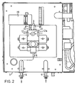
- Figure ? shows an arrangement which is generally similar to that shown in Figure 1 but the manifold block, valves, and associated components are mounted on lid of the water bath.
- two light dependent resistors 12, 12a are employed, the light source 13 being located between them, the light being seen by both resistors.
- the manifold includes four solenoid operated valves which are connected in two pairs. Each pair comprises a valve controlling the inlet 4 and outlet 6.
- the first pair of valves RA cause the inlet 4 to be connected to the end A 1 of the coil 3 and the outlet 8 of the coil 3 to be connected to the outlet 6.
- the other pair of solenoids RB when energised cause the inlet 4 to be connected to the end B 1 of the coil 3, and for the end A 1 of the coil 3 to be connected to the outlet 6.
- Appropriate energisation of either pair of coils establishes the direction of flow of beverage through the coil 3 and hence to the outlet 8.
- One or other pairs of the solenoids RA or RB are placed into circuit through changeover contacts associated with a relay C which is driven through transistor Q1 from the output of a bi-stable flip-flop FF.
- Relay C contacts are energised together with operation of the tap solenoid D and the pump relay E.
- the light dependent resistors are connected to one input of an operational amplifier F forming a latch and this is adjusted by a potentiometer G to establish the correct operating point.
- the output of the operational amplifier F drives transistor Q2 which is connected with relay H.
- the relay H is not energised.
- the button 9 serves to momentarily unbalance the operational amplifier and causes relay H to be energised, thus allowing the tap solenoid D and one or other pairs of the solenoids RA or RB to be energised via relay C.
- the beverage will be caused to flow in a direction which forces the ball 11 onto the seating at the end of the coil, and no beverage will be dispensed.
- the next operation of the button 9 will synchronise the system and cause the appropriate relay pair RA or RB to be energised according to the position of the ball 11.
Landscapes
- Physics & Mathematics (AREA)
- Fluid Mechanics (AREA)
- General Physics & Mathematics (AREA)
- Devices For Dispensing Beverages (AREA)
Priority Applications (1)
| Application Number | Priority Date | Filing Date | Title |
|---|---|---|---|
| EP80303905A EP0051094A1 (fr) | 1980-11-03 | 1980-11-03 | Appareil pour la mesure de liquides |
Applications Claiming Priority (1)
| Application Number | Priority Date | Filing Date | Title |
|---|---|---|---|
| EP80303905A EP0051094A1 (fr) | 1980-11-03 | 1980-11-03 | Appareil pour la mesure de liquides |
Publications (1)
| Publication Number | Publication Date |
|---|---|
| EP0051094A1 true EP0051094A1 (fr) | 1982-05-12 |
Family
ID=8187288
Family Applications (1)
| Application Number | Title | Priority Date | Filing Date |
|---|---|---|---|
| EP80303905A Withdrawn EP0051094A1 (fr) | 1980-11-03 | 1980-11-03 | Appareil pour la mesure de liquides |
Country Status (1)
| Country | Link |
|---|---|
| EP (1) | EP0051094A1 (fr) |
Citations (4)
| Publication number | Priority date | Publication date | Assignee | Title |
|---|---|---|---|---|
| GB1228776A (fr) * | 1967-08-24 | 1971-04-21 | ||
| DE2708684A1 (de) * | 1977-02-28 | 1978-08-31 | Hans Lindemann | Vorrichtung zum schrittweisen foerdern von fluessigkeitsmengen |
| GB2028767A (en) * | 1978-08-31 | 1980-03-12 | Distillers Co Yeast Ltd | Metering system for dispensing beer or other potable carbonate liquids |
| US4213544A (en) * | 1978-01-31 | 1980-07-22 | Pandolfi Alberto S | Water proportioning and delivering device particularly for coffee machines |
-
1980
- 1980-11-03 EP EP80303905A patent/EP0051094A1/fr not_active Withdrawn
Patent Citations (4)
| Publication number | Priority date | Publication date | Assignee | Title |
|---|---|---|---|---|
| GB1228776A (fr) * | 1967-08-24 | 1971-04-21 | ||
| DE2708684A1 (de) * | 1977-02-28 | 1978-08-31 | Hans Lindemann | Vorrichtung zum schrittweisen foerdern von fluessigkeitsmengen |
| US4213544A (en) * | 1978-01-31 | 1980-07-22 | Pandolfi Alberto S | Water proportioning and delivering device particularly for coffee machines |
| GB2028767A (en) * | 1978-08-31 | 1980-03-12 | Distillers Co Yeast Ltd | Metering system for dispensing beer or other potable carbonate liquids |
Similar Documents
| Publication | Publication Date | Title |
|---|---|---|
| US3993218A (en) | Liquor dispenser | |
| US5022557A (en) | Computerized beverage dispensing system | |
| CN107531475B (zh) | 饮料分配系统 | |
| US4889148A (en) | Flow control valve for a dispensing system | |
| EP0607376A1 (fr) | Dispositif servant au dosage volumetrique de produits | |
| EP0532062B1 (fr) | Distributeur de boissons avec dispositif de contrôle du rapport volumétrique | |
| JPH024697A (ja) | 後混合ジユース分配システム | |
| US3565287A (en) | Beverage dispensing and measuring unit | |
| JPH02258595A (ja) | 飲料分配弁及び分配方法 | |
| US3790028A (en) | Hot liquid dispenser | |
| US3819305A (en) | Liquid product control system | |
| US4953754A (en) | Beverage dispenser system using volumetric ratio control device | |
| US3455487A (en) | Fluid dispensing apparatus | |
| US3851127A (en) | Hot liquid dispenser reverse flow sensor with check valve slider and magnetically operated switch | |
| EP0051094A1 (fr) | Appareil pour la mesure de liquides | |
| US3464591A (en) | Dual-tap beer dispensing apparatus | |
| GB1591881A (en) | Liquid metering apparatus | |
| US3834586A (en) | Fluid measuring and dispensing system | |
| US3459332A (en) | Pneumatically controlled dispensing apparatus | |
| US5060824A (en) | Beverage dispenser system using volumetric ratio control device | |
| GB2260965A (en) | Metering and dispensing system | |
| US3628566A (en) | Multiple fluid control device | |
| US3813008A (en) | Liquid dispensing apparatus | |
| US5071038A (en) | Beverage dispenser system using volumetric ratio control device | |
| JP2002019887A (ja) | 飲料供給装置 |
Legal Events
| Date | Code | Title | Description |
|---|---|---|---|
| PUAI | Public reference made under article 153(3) epc to a published international application that has entered the european phase |
Free format text: ORIGINAL CODE: 0009012 |
|
| AK | Designated contracting states |
Designated state(s): AT BE CH DE FR IT LU NL SE |
|
| RBV | Designated contracting states (corrected) |
Designated state(s): AT BE CH DE FR IT LI LU NL SE |
|
| RBV | Designated contracting states (corrected) |
Designated state(s): AT BE CH DE FR IT LI LU NL SE |
|
| STAA | Information on the status of an ep patent application or granted ep patent |
Free format text: STATUS: THE APPLICATION IS DEEMED TO BE WITHDRAWN |
|
| 18D | Application deemed to be withdrawn |
Effective date: 19830414 |
|
| RIN1 | Information on inventor provided before grant (corrected) |
Inventor name: GLOVER, BRIAN HOWARD |