EP0051099A1 - Verfahren und Vorrichtung zum Herstellen einer endlosen Briefumschlagbahn oder dergleichen - Google Patents
Verfahren und Vorrichtung zum Herstellen einer endlosen Briefumschlagbahn oder dergleichen Download PDFInfo
- Publication number
- EP0051099A1 EP0051099A1 EP80401573A EP80401573A EP0051099A1 EP 0051099 A1 EP0051099 A1 EP 0051099A1 EP 80401573 A EP80401573 A EP 80401573A EP 80401573 A EP80401573 A EP 80401573A EP 0051099 A1 EP0051099 A1 EP 0051099A1
- Authority
- EP
- European Patent Office
- Prior art keywords
- sheet
- station
- sheets
- speed
- along
- Prior art date
- Legal status (The legal status is an assumption and is not a legal conclusion. Google has not performed a legal analysis and makes no representation as to the accuracy of the status listed.)
- Granted
Links
- 238000000034 method Methods 0.000 title claims description 16
- 238000007789 sealing Methods 0.000 claims abstract description 53
- 230000003313 weakening effect Effects 0.000 claims abstract description 17
- 238000011144 upstream manufacturing Methods 0.000 claims abstract description 13
- 238000004519 manufacturing process Methods 0.000 claims abstract description 8
- 238000005520 cutting process Methods 0.000 claims description 15
- 230000001133 acceleration Effects 0.000 claims description 12
- 230000009172 bursting Effects 0.000 claims description 5
- 238000005304 joining Methods 0.000 claims description 5
- 230000033228 biological regulation Effects 0.000 claims description 3
- 230000000977 initiatory effect Effects 0.000 claims description 3
- 238000005096 rolling process Methods 0.000 claims description 3
- 238000000926 separation method Methods 0.000 claims description 3
- 230000008030 elimination Effects 0.000 claims 1
- 238000003379 elimination reaction Methods 0.000 claims 1
- 230000001360 synchronised effect Effects 0.000 claims 1
- 238000007493 shaping process Methods 0.000 description 7
- 239000000853 adhesive Substances 0.000 description 6
- 238000007639 printing Methods 0.000 description 5
- 238000010438 heat treatment Methods 0.000 description 4
- 238000012986 modification Methods 0.000 description 4
- 230000004048 modification Effects 0.000 description 4
- 238000004026 adhesive bonding Methods 0.000 description 3
- 230000001070 adhesive effect Effects 0.000 description 3
- 239000011248 coating agent Substances 0.000 description 3
- 238000000576 coating method Methods 0.000 description 3
- 238000003780 insertion Methods 0.000 description 3
- 230000037431 insertion Effects 0.000 description 3
- 230000003287 optical effect Effects 0.000 description 3
- 230000000712 assembly Effects 0.000 description 2
- 238000000429 assembly Methods 0.000 description 2
- 230000015572 biosynthetic process Effects 0.000 description 2
- 238000004049 embossing Methods 0.000 description 2
- 238000000605 extraction Methods 0.000 description 2
- 239000003292 glue Substances 0.000 description 2
- 238000003825 pressing Methods 0.000 description 2
- 230000008569 process Effects 0.000 description 2
- 239000000126 substance Substances 0.000 description 2
- 238000011282 treatment Methods 0.000 description 2
- 238000003466 welding Methods 0.000 description 2
- 208000003629 Rupture Diseases 0.000 description 1
- 240000008042 Zea mays Species 0.000 description 1
- 235000005824 Zea mays ssp. parviglumis Nutrition 0.000 description 1
- 235000002017 Zea mays subsp mays Nutrition 0.000 description 1
- 230000004913 activation Effects 0.000 description 1
- 238000005452 bending Methods 0.000 description 1
- 235000020303 café frappé Nutrition 0.000 description 1
- 210000004027 cell Anatomy 0.000 description 1
- 239000000470 constituent Substances 0.000 description 1
- 235000005822 corn Nutrition 0.000 description 1
- 230000006866 deterioration Effects 0.000 description 1
- 238000011161 development Methods 0.000 description 1
- 238000010586 diagram Methods 0.000 description 1
- 230000006870 function Effects 0.000 description 1
- 238000007757 hot melt coating Methods 0.000 description 1
- 238000009434 installation Methods 0.000 description 1
- 239000000463 material Substances 0.000 description 1
- 230000015654 memory Effects 0.000 description 1
- 238000012545 processing Methods 0.000 description 1
- 230000001105 regulatory effect Effects 0.000 description 1
- 238000009958 sewing Methods 0.000 description 1
- 230000001629 suppression Effects 0.000 description 1
- 238000012546 transfer Methods 0.000 description 1
- 239000002699 waste material Substances 0.000 description 1
Images

Classifications
-
- B—PERFORMING OPERATIONS; TRANSPORTING
- B42—BOOKBINDING; ALBUMS; FILES; SPECIAL PRINTED MATTER
- B42C—BOOKBINDING
- B42C3/00—Making booklets, pads, or form sets from multiple webs
-
- B—PERFORMING OPERATIONS; TRANSPORTING
- B31—MAKING ARTICLES OF PAPER, CARDBOARD OR MATERIAL WORKED IN A MANNER ANALOGOUS TO PAPER; WORKING PAPER, CARDBOARD OR MATERIAL WORKED IN A MANNER ANALOGOUS TO PAPER
- B31B—MAKING CONTAINERS OF PAPER, CARDBOARD OR MATERIAL WORKED IN A MANNER ANALOGOUS TO PAPER
- B31B2150/00—Flexible containers made from sheets or blanks, e.g. from flattened tubes
- B31B2150/002—Flexible containers made from sheets or blanks, e.g. from flattened tubes by joining superimposed sheets, e.g. with separate bottom sheets
-
- B—PERFORMING OPERATIONS; TRANSPORTING
- B31—MAKING ARTICLES OF PAPER, CARDBOARD OR MATERIAL WORKED IN A MANNER ANALOGOUS TO PAPER; WORKING PAPER, CARDBOARD OR MATERIAL WORKED IN A MANNER ANALOGOUS TO PAPER
- B31B—MAKING CONTAINERS OF PAPER, CARDBOARD OR MATERIAL WORKED IN A MANNER ANALOGOUS TO PAPER
- B31B2160/00—Shape of flexible containers
- B31B2160/10—Shape of flexible containers rectangular and flat, i.e. without structural provision for thickness of contents
-
- B—PERFORMING OPERATIONS; TRANSPORTING
- B31—MAKING ARTICLES OF PAPER, CARDBOARD OR MATERIAL WORKED IN A MANNER ANALOGOUS TO PAPER; WORKING PAPER, CARDBOARD OR MATERIAL WORKED IN A MANNER ANALOGOUS TO PAPER
- B31B—MAKING CONTAINERS OF PAPER, CARDBOARD OR MATERIAL WORKED IN A MANNER ANALOGOUS TO PAPER
- B31B2170/00—Construction of flexible containers
- B31B2170/20—Construction of flexible containers having multi-layered walls, e.g. laminated or lined
Definitions
- the invention relates to folds which are presented in a continuous strip for correspondence or the dissemination of confidential information (pay slips for example).
- Such bands are formed by bundles of continuous sheets, folded in a screen, each of which constitutes a unitary fold.
- These products which are generally given the English name of "mailers”, allow editing on a printing machine such as a computer printer, electro-accounting equipment or the like.
- the lower sheet of the bundle is intended to form for each of the shutters of the folding screen, that is to say for each of the unit folds, the back of the envelope of the fold considered, while the upper sheet forms the faces envelopes.
- All the intermediate sheets are intended to constitute the interior documents or inserts of each of the folds.
- the typing of the printer is selectively transferred to some of the sheets, therefore to some of the interior documents, while non-personalized mentions are ie identical for all the folds, are printed on one or more sheets before their assembly.
- the bundle also has a cover strip, called an archive or control strip, which covers the upper sheet.
- this tape was mainly intended to collect all of the information entered by the printer in order to allow a possible later control, hence the name of the tape, but at present the capacity of the memories of the .computers render this function useless and the control strip still exists only to "retain" information which must not appear on the upper sheet, that is to say most often all information other than the addresses of recipients which are reported on said upper sheet thanks to carbonaceous pads judiciously placed on the back of the control strip.
- the lower and upper sheets at least are joined by bonding along their side edges.
- each of the flaps or folds is sealed at the head and at the bottom by transverse adhesive threads joining the upper and lower sheets through transverse cutouts made on all the intermediate sheets.
- Detachable perforation lines and / or breaking points allow the recipients to open the folds and extract the interior documents.
- the bundle is provided with drive perforations located in a detachable marginal zone. These perforations are used to drive the bundle in the printing machine and then in the unitizing device.
- the bundle After the passage in the printer the bundle is brought to a unitizing device where after removal of the possible strip of cover, the folds are separated from each other along the folding lines in screen either by breaking by either by cutting (cutter). Very often, at the entry of the device, longitudinal cutting wheels detach the marginal zones carrying the drive perforations, but this arrangement is not compulsory, the separation of these zones can be carried out on each fold by its recipient if longitudinal lines of detachable perforations have been provided.
- unit fold assemblies There are many types of such unit fold assemblies; they sometimes differ from each other by the arrangement of the interior documents, but most often by the arrangement of the lines of detachable perforations and of initiation of rupture, so as to allow a simplification of the mode of opening of the fold and extraction. inserts.
- the method according to the invention makes it possible to obtain a continuous assembly of folds with free interior documents, from continuous sheets not comprising transverse cuts, which completely eliminates the drawbacks d and e.
- This process can be implemented with simple equipment, at the user's place, therefore possibly after the passage of at least one of the continuous sheets in the printer, which makes it possible to eliminate the drawbacks a, b and c .
- the invention provides a manufacturing process conventionally comprising the joining of a lower continuous sheet and an upper continuous sheet, by sealing along their longitudinal edges and along transverse bands overlapping concordant lines of weakness, of constant spacing E 1 and intended for the separation of the unit into unitary plies, sealing produced in particular by pressure in a station comprising at the inlet at least one pair of driving rollers between which are engaged the two sheets conveyed towards said inlet at the same running speed V 1 , equal to the tangential speed of the driving rollers, along separate paths.
- each intermediate sheet can be carried out in different ways, for example by cutting using rotary knives, or by breaking after incision by means of abrupt but very brief acceleration, or even by conventional breaking obtained by a sharp acceleration of scrolling determining the bursting of the weakening lines.
- the invention relates only to the mode of insertion of the sheet or sheets intended to form the interior documents and before assembly each sheet is capable of receiving the most diverse treatments or shapings.
- the sealing device varies according to the means provided.
- the joining of the lower and upper sheets on the periphery of each of their flaps can result from a simple embossing or crimp-locking, or from stapling or sewing. Sealing can also be obtained by welding with or without the addition of material. Most often, however, the joining will be by bonding, either by simple bonding, threads of adhesive being deposited on at least one of the upper and lower sheets, or by self-bonding, threads of self-adhesive substance being deposited on each of the two lower and upper sheets, or else by heat-bonding after coating with threads of heat-activated adhesive on at least one of the sheets.
- the device will comprise, downstream of the driving rollers, at least one pair of pressure rollers and, in the case of heat-bonding, at least one of the pairs of pressure rollers will be constituted by heating rollers.
- the pressure rollers possibly heating, can be smooth cylinders, but when the total thickness of the interior documents becomes large, it is advantageous to provide hollow impression rollers, the development of each imprint corresponding to the interior of the sealing frame of a unitary fold.
- the method according to the invention can be applied to the manufacture of a continuous set of sealed plies, intended to pass through a machine printer, but it is particularly indicated in the case where the interior documents must receive a direct strike, that is to say the cases where the assembly is carried out at the user's place.
- the invention also relates to a device for implementing the method, comprising for each sheet a separate circuit along which it is guided and driven by spindle coaches cooperating with perforations formed along its longitudinal edges, said circuit leading to a pair of driving rollers, rolling against each other, which constitutes the entrance to a pressure sealing station.
- This device is remarkable in that the spikes of the circuit of each intermediate sheet rotates more slowly than those of the circuits of the lower and upper sheets, 1 1 spacing of the lines of weakness provided on each of the sheets for uniting folds being directly proportional to the running speed of the sheet in question, that on the path of each intermediate sheet is arranged, upstream of the sealing station, a device for cutting the edge for eliminating the perforated drive margins, then a device for unitizing by sectioning along the lines of weakness and for routing the successive sections of the intermediate sheet thus formed to the entry driving rollers of the sealing station, where they are introduced between said rollers and between the two lower and upper sheets, is provided by transport means such as the average speed between the instant of the rup ture and that of the entry to the sealing station is substantially equal to the running speed V 1 of the lower and upper sheets mentioned above.
- the device according to the invention will be disposed between the outlet of a conventional shaping machine comprising all or part of printing stations, perforations, cutting, coating sealing means. and the entrance to a folding folding screen.
- this device can be made available to a user. In this case, it is arranged upstream of a unitizing machine (breaker for example) and each of its circuits is then supplied by an appropriate continuous sheet, folded in a screen, after passage of at least one of the intermediate sheets in a machine printer, the upper sheet preferably comprising a rectangular cut out opposite the location d identification of the recipient in order to avoid any need for tracking.
- each intermediate sheet can be carried out by any known means: instant accelerator cooperating with a break-in knife, rotary cutting device, or even conventional breaker printing a strong acceleration of the sheet considered, but followed by '' at least one pair of drive and regulation rollers whose variable speed is regulated by a scroll detector.
- the assembly includes three layers, namely, a lower sheet 11, an upper sheet 12 and an intermediate sheet 10.
- Each of said sheets has along perforations at least one of its longitudinal edges ( lOb, llb, 12b) and is guided and driven along a respective circuit, symbolized here by a support roller (14, 15, 16), by spike trainers (17, 18, 19).
- Each sheet carries equidistant transverse lines of weakness (10a, lla, 12a), two successive lines delimiting a flap corresponding to a unitary fold.
- the spacing E 1 of the weakening lines is greater than that E 2 presented by the weakening lines 10a of the intermediate sheet 10.
- At least one of the lower 11 and upper sheets 12 carries sealing means along its longitudinal edges (inside with respect to the perforated margins of drag) and sealing means overlapping the transverse lines of weakness 11a, 12a, these sealing means being activated by pressure or by heat and pressure.
- the assembly is carried out in a sealing station 20, the inlet of which consists of a pair of driving rollers 13 rolling one on top of the other, and between which the various sheets are engaged, possibly after not on rollers. reference 21.
- the upper and lower sheets are secured, over the entire periphery to each of their flaps by means of pressing cylinders 22 which may be heated (in the case where the sealing means are constituted by threads of thermo glue -adhesive).
- the pressing cylinders 22 can be hollow impressions when the thickness of the interior documents of each of the plies requires it.
- the intermediate sheet 10 is a little narrower than the sheets 11 and 12.
- the height E 2 of the flaps of the sheet 10 is less than the height E 1 of the flaps of the sheets 11 and 12.
- the difference in width and the height of the flaps of the strip 10 relative to those of the strips 11 and 12 is at least twice the width of a sealing thread so that the interior document can fit entirely inside the sealing frame. It then suffices that the upper edge of a flap of the sheet 10 is engaged between the driving rollers 13 slightly later than the upper edges. of the flaps of the sheets 11 and 12 and that said intermediate flap is detached from the continuous strip 10 to be accommodated properly between the sheets 11 and 12.
- the rollers 13 have a tangential speed equal to the running speed V 1 of the sheets 11 and 12, while the scrolling speed V 2 of sheet 10 imposed by the trainers; such that 17 is less than V 1 and such that
- the sheet 10 is subjected to a very sudden acceleration which causes the bursting of said sheet along the nearest line of weakness 10a, released from the pins.
- the burst occurs at the time of acceleration and a temporary ripple is formed immediately downstream of the accelerator means, without there being any modification of the scrolling both at speed V 2 upstream and at speed V downstream .
- the instantaneous accelerator can be constituted for example by a pair of rollers 24, 25 of which at least one 24 is both motor and of elliptical section, and whose tangential speed at the end of the major axis is, for example , equal to twice V 2 .
- an edge cutter 26 can be provided upstream of the knife 23.
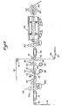
- FIG. 2 there is an assembly 136 of three sheets, namely a lower sheet 111, an upper sheet 112 and an intermediate sheet 110. Each of these sheets follows a separate path leading it, possibly after passing over rollers of reference 121, at the input 144 of a sealing station where it is caught between two driving rollers 113.
- the flaps of at least one of the lower 111 and upper 112 sheets each include a frame hot melt coating device and the sealing station is a station thermosouda e g with an oven 143 and hollow impression pressure rollers 122 as mentioned above.
- the sheets 111 and 112 pass at the same speed V imposed by spike coaches (not shown) which cooperate with marginal perforations of said sheets, the driving rollers 113 have a tangential speed equal to V 1 and the set of two sheets 111 and 112 enclosing the intermediate sheets such as 110 is taken up, immediately downstream of the rollers 113, by spiked conveyors 141 rotating at speed V 1 .
- the pressure rollers 122 rotate at the same speed which is the running speed of the assembly 136 at the outlet of the sealing station.
- the sheet 110 is narrower than the sheets 111 and 112 which, themselves, are of the same width in order to be able to overlap exactly.
- Each sheet has equidistant transverse lines of weakening. The spacing of these lines is E 1 on the sheets 111 and 112 and E 2 ⁇ E 1 on the sheet 110.
- the sheet 110 scrolls at a speed V 2 , imposed by spike trainers -117, such than
- the invention resides in the mode of insertion of the intermediate sheet 110 or, more precisely, of sections coming from the bursting of the sheet 110 along its transverse lines of weakness.
- the sheet 110 passes through a single or double edge cutter 126 depending on whether the sheet has marginal drive perforations along a single edge (for example, wide sheet folded longitudinally at the entrance to its respective route) or along its two longitudinal edges.
- the edge cutter 126 comprises, in a known manner, a knurling device 126a for continuously cutting the corresponding marginal zone and a rotary cutter 126b for reducing into short pieces the continuous strip detached by the knobs 126a.
- the sheet 110 Downstream of the edge cutter 126, the sheet 110 passes through a "spark gap" or breaker constituted essentially, in a traditional manner, on the one hand, by two pairs of rollers, namely a first pair 130 whose tangential speed is substantially equal at V and a second pair of rollers 131 whose tangential speed is substantially equal to 2 V and, on the other hand, by a wedge 133 of initiation of rupture arranged between the two pairs of above-mentioned rollers and intended to lower to the passage of each weakening line so as to "sink" it over at least part of its length.
- a spark gap or breaker constituted essentially, in a traditional manner, on the one hand, by two pairs of rollers, namely a first pair 130 whose tangential speed is substantially equal at V and a second pair of rollers 131 whose tangential speed is substantially equal to 2 V and, on the other hand, by a wedge 133 of initiation of rupture arranged between the two pairs of above-mentione
- each section of the sheet 10 is taken up by retarder rollers 132 whose speed is automatically adjusted by the signals coming from a position indicator 135 so that the spacing between two sections of successive sheets is constant and equal to E1 - E2 , which amounts to saying that the retarder rollers 132 reduce the average speed between the moment of failure and the inlet 144 of the sealing station to a value substantially equal to V 1 .
- each section must be taken by a downstream drive means at the latest when it escapes from an upstream drive means, this that is to say that it is necessary to be able to adjust the spacing of the different stations (26, 23, 24, 13 and 126, 133, 131, 132, 113) according to the format E of the flaps of the sheet 10 or 110.
- these various positions can slide along slides provided on the machine and be locked in relative position, the sliding paths of the sheet 10 or 110 then sections of this sheet being constituted by belts which can be unwound from retractable reels elastic as shown by way of example , in FIG. 2, with the sliding belts 137 and 138 and their respective reels 139 and 140.
- the device of FIG. 1 or of FIG. 2 is incorporated in the chain of fa- brigation and forms part of the shaping machine.
- Each sheet takes place from a respective reel and passes through the various traditional printing, perforating, cutting, gluing or other coating stations to arrive at the terminal part shown.
- the scrolling of the intermediate sheets must be slower than that of the upper and lower sheets from one end of the shaping to the other.
- the shaping is completed in a folding folding station, possibly after addition by lateral embossing of a cover strip.
- the method of inserting interior documents with the device is particularly suitable for implementation by the user, which makes it possible to solve many problems. Indeed, it suffices for the user to feed the device from "screens" of the various sheets, sheets 11 and 12 (or 111 and 112) being supplied to him, possibly with various prints, ready to use and sheets 10 (or 110) having been previously filled in by its machine printer (by simple typing, or in Y with longitudinal folding). Thus, at least one, but possibly all interior documents can receive a direct strike allowing an exploitation by optical or magnetic reading.
- the upper sheet 12 (or 112) is provided with windows 27 corresponding to the location of the identification of the recipient on the sheet 10 (or 110); however, to eliminate possible waste, it is useful to provide at various points with circuits of the various sheets of presence indicators (feelers or photocells).
- the invention is not limited to the embodiment described and shown. First of all, it only concerns the mode of insertion of the interior document (s), whatever the treatments and shapings undergone by the continuous sheets before they are superimposed and whatever the means of assembling the upper and lower sheets ( bonding, welding, heat sealing by heating cylinders or by passage through an oven or by any other heating means, etc.). In addition, modifications can be made to the mechanical means used for implementing the method, without thereby departing from the scope of the invention.
Landscapes
- Making Paper Articles (AREA)
- Folding Of Thin Sheet-Like Materials, Special Discharging Devices, And Others (AREA)
Priority Applications (3)
| Application Number | Priority Date | Filing Date | Title |
|---|---|---|---|
| DE8080401573T DE3067569D1 (en) | 1980-11-04 | 1980-11-04 | Method and device for making continuous mailing envelope forms or others |
| EP80401573A EP0051099B1 (de) | 1980-11-04 | 1980-11-04 | Verfahren und Vorrichtung zum Herstellen einer endlosen Briefumschlagbahn oder dergleichen |
| AT80401573T ATE7123T1 (de) | 1980-11-04 | 1980-11-04 | Verfahren und vorrichtung zum herstellen einer endlosen briefumschlagbahn oder dergleichen. |
Applications Claiming Priority (1)
| Application Number | Priority Date | Filing Date | Title |
|---|---|---|---|
| EP80401573A EP0051099B1 (de) | 1980-11-04 | 1980-11-04 | Verfahren und Vorrichtung zum Herstellen einer endlosen Briefumschlagbahn oder dergleichen |
Publications (2)
| Publication Number | Publication Date |
|---|---|
| EP0051099A1 true EP0051099A1 (de) | 1982-05-12 |
| EP0051099B1 EP0051099B1 (de) | 1984-04-18 |
Family
ID=8187401
Family Applications (1)
| Application Number | Title | Priority Date | Filing Date |
|---|---|---|---|
| EP80401573A Expired EP0051099B1 (de) | 1980-11-04 | 1980-11-04 | Verfahren und Vorrichtung zum Herstellen einer endlosen Briefumschlagbahn oder dergleichen |
Country Status (3)
| Country | Link |
|---|---|
| EP (1) | EP0051099B1 (de) |
| AT (1) | ATE7123T1 (de) |
| DE (1) | DE3067569D1 (de) |
Cited By (5)
| Publication number | Priority date | Publication date | Assignee | Title |
|---|---|---|---|---|
| GB2134879A (en) * | 1983-01-25 | 1984-08-22 | Ragnar Olof Winberg | A sealed letter-packet and method for the manufacture thereof |
| US4850949A (en) * | 1986-08-12 | 1989-07-25 | Herve Et Fils Sa | Apparatus for folding a band into accordion pleats including three panels |
| EP0185811B1 (de) * | 1984-12-19 | 1990-03-28 | Iseto Shiko Co. Limited | Apparat für die Fertigung versiegelter Umschlagzusammensetzungen |
| WO1991004216A1 (de) * | 1989-09-14 | 1991-04-04 | Bernhard Ehret | Vorrichtung zum zusammentragen von flächigen bahnen zu mehrblattformularen, sowie rollen- oder stapelcollator dafür |
| US5403428A (en) * | 1990-10-12 | 1995-04-04 | Toyo Shokuhin Kikai Kabushiki Kaisha | Apparatus for producing communication articles including postcards and envelopes |
Citations (6)
| Publication number | Priority date | Publication date | Assignee | Title |
|---|---|---|---|---|
| US3526562A (en) * | 1965-10-22 | 1970-09-01 | Ernest A Dahl Jr | Magnetically actuatable business machine card,method of making the same and apparatus therefor |
| US3902655A (en) * | 1974-05-13 | 1975-09-02 | Harold W Huffman | Method of producing multi-panel mailing envelope forms in side-by-side interconnected series |
| FR2289405A1 (fr) * | 1974-10-31 | 1976-05-28 | Standard Register Cy | File continue d'enveloppes contenant un encart |
| FR2365491A1 (fr) * | 1976-09-28 | 1978-04-21 | Herve & Fils Sa | Assemblages superposables pour la constitution de plis postaux ou autres |
| FR2418749A1 (fr) * | 1978-03-04 | 1979-09-28 | Haag & Sohn Gmbh R | Pochette pour documents, tels que films et tirages photographiques, et unite de fabrication pour son obtention |
| FR2431983A1 (fr) * | 1978-05-19 | 1980-02-22 | Moore Business Forms Ltd | Appareil a plier, thermocoller et detacher des bandes |
Family Cites Families (1)
| Publication number | Priority date | Publication date | Assignee | Title |
|---|---|---|---|---|
| US4095695A (en) * | 1977-04-18 | 1978-06-20 | Wallace Business Forms, Inc. | Stuffed sealed envelope assembly and method of making |
-
1980
- 1980-11-04 EP EP80401573A patent/EP0051099B1/de not_active Expired
- 1980-11-04 AT AT80401573T patent/ATE7123T1/de not_active IP Right Cessation
- 1980-11-04 DE DE8080401573T patent/DE3067569D1/de not_active Expired
Patent Citations (6)
| Publication number | Priority date | Publication date | Assignee | Title |
|---|---|---|---|---|
| US3526562A (en) * | 1965-10-22 | 1970-09-01 | Ernest A Dahl Jr | Magnetically actuatable business machine card,method of making the same and apparatus therefor |
| US3902655A (en) * | 1974-05-13 | 1975-09-02 | Harold W Huffman | Method of producing multi-panel mailing envelope forms in side-by-side interconnected series |
| FR2289405A1 (fr) * | 1974-10-31 | 1976-05-28 | Standard Register Cy | File continue d'enveloppes contenant un encart |
| FR2365491A1 (fr) * | 1976-09-28 | 1978-04-21 | Herve & Fils Sa | Assemblages superposables pour la constitution de plis postaux ou autres |
| FR2418749A1 (fr) * | 1978-03-04 | 1979-09-28 | Haag & Sohn Gmbh R | Pochette pour documents, tels que films et tirages photographiques, et unite de fabrication pour son obtention |
| FR2431983A1 (fr) * | 1978-05-19 | 1980-02-22 | Moore Business Forms Ltd | Appareil a plier, thermocoller et detacher des bandes |
Cited By (5)
| Publication number | Priority date | Publication date | Assignee | Title |
|---|---|---|---|---|
| GB2134879A (en) * | 1983-01-25 | 1984-08-22 | Ragnar Olof Winberg | A sealed letter-packet and method for the manufacture thereof |
| EP0185811B1 (de) * | 1984-12-19 | 1990-03-28 | Iseto Shiko Co. Limited | Apparat für die Fertigung versiegelter Umschlagzusammensetzungen |
| US4850949A (en) * | 1986-08-12 | 1989-07-25 | Herve Et Fils Sa | Apparatus for folding a band into accordion pleats including three panels |
| WO1991004216A1 (de) * | 1989-09-14 | 1991-04-04 | Bernhard Ehret | Vorrichtung zum zusammentragen von flächigen bahnen zu mehrblattformularen, sowie rollen- oder stapelcollator dafür |
| US5403428A (en) * | 1990-10-12 | 1995-04-04 | Toyo Shokuhin Kikai Kabushiki Kaisha | Apparatus for producing communication articles including postcards and envelopes |
Also Published As
| Publication number | Publication date |
|---|---|
| DE3067569D1 (en) | 1984-06-28 |
| EP0051099B1 (de) | 1984-04-18 |
| ATE7123T1 (de) | 1984-05-15 |
Similar Documents
| Publication | Publication Date | Title |
|---|---|---|
| CA1075279A (fr) | Assemblage continu d'articles de correspondance postale | |
| US4455809A (en) | Process and apparatus for manufacturing continuous sealed postal or other envelope assemblies | |
| EP0693424B1 (de) | Verfahren und Vorrichtung zur Herstellung von Verpackungszuschnitten | |
| US3894905A (en) | Machine for making addressed and filled envelopes in a single operation | |
| US5095682A (en) | Mailer and method and apparatus for making | |
| EP0051099B1 (de) | Verfahren und Vorrichtung zum Herstellen einer endlosen Briefumschlagbahn oder dergleichen | |
| EP0541836A1 (de) | Verfahren zum Herstellen von Versandstücken | |
| EP0187083B1 (de) | Anhaltende Verbindung von Postbriefen oder dergleichen | |
| US4161091A (en) | Apparatus for making a connected series of stuffed sealed envelope assemblies | |
| CA1149659A (fr) | Procede et dispositif de fabrication d'assemblages de plis postaux ou similaires | |
| FR2888774A1 (fr) | Procede de fabrication de plis courriers et machine mettant en oeuvre ledit procede | |
| JP2001505143A (ja) | 枚数にむらのある通信文を自動的に封筒詰めするための機械および方法 | |
| FR2466339A1 (fr) | Procede de fabrication d'assemblages continus de plis postaux ou autres | |
| EP0049661B1 (de) | Verfahren zur kontinuierlichen Herstellung von durch Datenverarbeitungsanlagen mit personenbezüglichen Informationen versehenen Briefkarten und nach diesem Verfahren hergestellte Briefkarten | |
| EP0256194B1 (de) | Vorrichtung und Verfahren zum Falten einer Bahn in zusammenhängende dreiteilige Faltblätter | |
| JP3166087B2 (ja) | アジロ製本用ミシン入れ方法および装置 | |
| EP0592308B2 (de) | Band mit selbsklebenden Etiketten und automatische Etikettenabgabevorrichtung | |
| FR2668979A1 (fr) | Assemblage continu d'enveloppes a bords degages. | |
| EP0853005B1 (de) | Verfahren zur Herstellung von Formularen und nach diesem Verfahren hergestelltes Formular | |
| JP2517460B2 (ja) | 隠蔽葉書の製造装置 | |
| FR2715604A1 (fr) | Système intégré pour la fabrication et la manipulation de matières d'emballage utilisées pour l'archivage de films photographiques développés. | |
| EP0665123B1 (de) | Herstellungskombination für eine Serie von Indivisualtaschen | |
| EP0573720B1 (de) | Umschlag für Dokumente und Verfahren zu seiner Herstellung | |
| JP3253326B2 (ja) | メール作成装置 | |
| BE699913A (de) |
Legal Events
| Date | Code | Title | Description |
|---|---|---|---|
| PUAI | Public reference made under article 153(3) epc to a published international application that has entered the european phase |
Free format text: ORIGINAL CODE: 0009012 |
|
| 17P | Request for examination filed |
Effective date: 19811019 |
|
| AK | Designated contracting states |
Designated state(s): AT BE CH DE FR GB IT LU NL SE |
|
| ITF | It: translation for a ep patent filed | ||
| GRAA | (expected) grant |
Free format text: ORIGINAL CODE: 0009210 |
|
| AK | Designated contracting states |
Designated state(s): AT BE CH DE FR GB IT LI LU NL SE |
|
| REF | Corresponds to: |
Ref document number: 7123 Country of ref document: AT Date of ref document: 19840515 Kind code of ref document: T |
|
| REF | Corresponds to: |
Ref document number: 3067569 Country of ref document: DE Date of ref document: 19840628 |
|
| PLBE | No opposition filed within time limit |
Free format text: ORIGINAL CODE: 0009261 |
|
| STAA | Information on the status of an ep patent application or granted ep patent |
Free format text: STATUS: NO OPPOSITION FILED WITHIN TIME LIMIT |
|
| 26N | No opposition filed | ||
| ITTA | It: last paid annual fee | ||
| PGFP | Annual fee paid to national office [announced via postgrant information from national office to epo] |
Ref country code: BE Payment date: 19911022 Year of fee payment: 12 |
|
| PGFP | Annual fee paid to national office [announced via postgrant information from national office to epo] |
Ref country code: LU Payment date: 19911024 Year of fee payment: 12 |
|
| PGFP | Annual fee paid to national office [announced via postgrant information from national office to epo] |
Ref country code: CH Payment date: 19911028 Year of fee payment: 12 |
|
| PGFP | Annual fee paid to national office [announced via postgrant information from national office to epo] |
Ref country code: AT Payment date: 19911029 Year of fee payment: 12 |
|
| PGFP | Annual fee paid to national office [announced via postgrant information from national office to epo] |
Ref country code: SE Payment date: 19911112 Year of fee payment: 12 |
|
| PGFP | Annual fee paid to national office [announced via postgrant information from national office to epo] |
Ref country code: DE Payment date: 19911115 Year of fee payment: 12 |
|
| PGFP | Annual fee paid to national office [announced via postgrant information from national office to epo] |
Ref country code: NL Payment date: 19911130 Year of fee payment: 12 |
|
| PGFP | Annual fee paid to national office [announced via postgrant information from national office to epo] |
Ref country code: GB Payment date: 19911204 Year of fee payment: 12 |
|
| EPTA | Lu: last paid annual fee | ||
| PG25 | Lapsed in a contracting state [announced via postgrant information from national office to epo] |
Ref country code: LU Free format text: LAPSE BECAUSE OF NON-PAYMENT OF DUE FEES Effective date: 19921104 Ref country code: GB Effective date: 19921104 Ref country code: AT Effective date: 19921104 |
|
| PG25 | Lapsed in a contracting state [announced via postgrant information from national office to epo] |
Ref country code: SE Effective date: 19921105 |
|
| PGFP | Annual fee paid to national office [announced via postgrant information from national office to epo] |
Ref country code: FR Payment date: 19921119 Year of fee payment: 13 |
|
| PG25 | Lapsed in a contracting state [announced via postgrant information from national office to epo] |
Ref country code: LI Effective date: 19921130 Ref country code: CH Effective date: 19921130 Ref country code: BE Effective date: 19921130 |
|
| BERE | Be: lapsed |
Owner name: HERVE ET FILS S.A. Effective date: 19921130 |
|
| PG25 | Lapsed in a contracting state [announced via postgrant information from national office to epo] |
Ref country code: NL Effective date: 19930601 |
|
| GBPC | Gb: european patent ceased through non-payment of renewal fee |
Effective date: 19921104 |
|
| NLV4 | Nl: lapsed or anulled due to non-payment of the annual fee | ||
| REG | Reference to a national code |
Ref country code: CH Ref legal event code: PL |
|
| PG25 | Lapsed in a contracting state [announced via postgrant information from national office to epo] |
Ref country code: DE Effective date: 19930803 |
|
| PG25 | Lapsed in a contracting state [announced via postgrant information from national office to epo] |
Ref country code: FR Effective date: 19940729 |
|
| REG | Reference to a national code |
Ref country code: FR Ref legal event code: ST |
|
| EUG | Se: european patent has lapsed |
Ref document number: 80401573.3 Effective date: 19930610 |