EP0051130B1 - Koaxiale Buchsensteckverbindung - Google Patents
Koaxiale Buchsensteckverbindung Download PDFInfo
- Publication number
- EP0051130B1 EP0051130B1 EP81107054A EP81107054A EP0051130B1 EP 0051130 B1 EP0051130 B1 EP 0051130B1 EP 81107054 A EP81107054 A EP 81107054A EP 81107054 A EP81107054 A EP 81107054A EP 0051130 B1 EP0051130 B1 EP 0051130B1
- Authority
- EP
- European Patent Office
- Prior art keywords
- contact
- connector according
- coaxial plug
- type sleeve
- sleeve
- Prior art date
- Legal status (The legal status is an assumption and is not a legal conclusion. Google has not performed a legal analysis and makes no representation as to the accuracy of the status listed.)
- Expired
Links
Images


Classifications
-
- H—ELECTRICITY
- H01—ELECTRIC ELEMENTS
- H01R—ELECTRICALLY-CONDUCTIVE CONNECTIONS; STRUCTURAL ASSOCIATIONS OF A PLURALITY OF MUTUALLY-INSULATED ELECTRICAL CONNECTING ELEMENTS; COUPLING DEVICES; CURRENT COLLECTORS
- H01R24/00—Two-part coupling devices, or either of their cooperating parts, characterised by their overall structure
- H01R24/38—Two-part coupling devices, or either of their cooperating parts, characterised by their overall structure having concentrically or coaxially arranged contacts
- H01R24/40—Two-part coupling devices, or either of their cooperating parts, characterised by their overall structure having concentrically or coaxially arranged contacts specially adapted for high frequency
- H01R24/52—Two-part coupling devices, or either of their cooperating parts, characterised by their overall structure having concentrically or coaxially arranged contacts specially adapted for high frequency mounted in or to a panel or structure
-
- H—ELECTRICITY
- H01—ELECTRIC ELEMENTS
- H01R—ELECTRICALLY-CONDUCTIVE CONNECTIONS; STRUCTURAL ASSOCIATIONS OF A PLURALITY OF MUTUALLY-INSULATED ELECTRICAL CONNECTING ELEMENTS; COUPLING DEVICES; CURRENT COLLECTORS
- H01R13/00—Details of coupling devices of the kinds covered by groups H01R12/70 or H01R24/00 - H01R33/00
- H01R13/02—Contact members
- H01R13/33—Contact members made of resilient wire
-
- H—ELECTRICITY
- H01—ELECTRIC ELEMENTS
- H01R—ELECTRICALLY-CONDUCTIVE CONNECTIONS; STRUCTURAL ASSOCIATIONS OF A PLURALITY OF MUTUALLY-INSULATED ELECTRICAL CONNECTING ELEMENTS; COUPLING DEVICES; CURRENT COLLECTORS
- H01R13/00—Details of coupling devices of the kinds covered by groups H01R12/70 or H01R24/00 - H01R33/00
- H01R13/46—Bases; Cases
- H01R13/50—Bases; Cases formed as an integral body
-
- H—ELECTRICITY
- H01—ELECTRIC ELEMENTS
- H01R—ELECTRICALLY-CONDUCTIVE CONNECTIONS; STRUCTURAL ASSOCIATIONS OF A PLURALITY OF MUTUALLY-INSULATED ELECTRICAL CONNECTING ELEMENTS; COUPLING DEVICES; CURRENT COLLECTORS
- H01R43/00—Apparatus or processes specially adapted for manufacturing, assembling, maintaining, or repairing of line connectors or current collectors or for joining electric conductors
- H01R43/20—Apparatus or processes specially adapted for manufacturing, assembling, maintaining, or repairing of line connectors or current collectors or for joining electric conductors for assembling or disassembling contact members with insulating base, case or sleeve
- H01R43/24—Assembling by moulding on contact members
-
- Y—GENERAL TAGGING OF NEW TECHNOLOGICAL DEVELOPMENTS; GENERAL TAGGING OF CROSS-SECTIONAL TECHNOLOGIES SPANNING OVER SEVERAL SECTIONS OF THE IPC; TECHNICAL SUBJECTS COVERED BY FORMER USPC CROSS-REFERENCE ART COLLECTIONS [XRACs] AND DIGESTS
- Y10—TECHNICAL SUBJECTS COVERED BY FORMER USPC
- Y10S—TECHNICAL SUBJECTS COVERED BY FORMER USPC CROSS-REFERENCE ART COLLECTIONS [XRACs] AND DIGESTS
- Y10S439/00—Electrical connectors
- Y10S439/93—Coupling part wherein contact is comprised of a wire or brush
Definitions
- the invention is based on a coaxial socket connector according to the preamble of claim 1
- coaxial socket connectors are used in devices in the entertainment industry, e.g. in hi-fi systems, used for the transmission of sound frequencies. They can also be used for teaching systems with a single-board computer or for machine controls. Another area of application is video technology.
- a plug socket is already known, in which an insulating body surrounded by a metallic shielding cap is inserted into a printed circuit by means of U-shaped support tabs.
- the insulating body made of plastic has a central opening, into which a contact sleeve designed as an internal contact and made from a flat sheet metal part is held with play.
- This contact sleeve is supported for axial fixation by means of bends on an end face of the insulating body.
- spring tongues of the contact sleeve which are spread outward leave a deposit which adjoins the central opening.
- the contact sleeve is provided with a connection lug that serves as a solder connection. Since the socket is inserted into an opening in the printed circuit, the connector is perpendicular to the printed circuit.
- a multiple arrangement of a coaxial socket connector referred to as a cinch connector is already known from the magazine "Asian Sources Electronics Components" September 1980 p. 346, in which the connector direction is parallel to the printed circuit.
- a metal contact sleeve is held as an external contact in a plastic support body. This contact sleeve has a connection lug bent downwards.
- An insulator insert which has a central opening, is inserted into this contact sleeve. The internal contact is located in the opening, the terminal lug of which is also bent downwards.
- the object of the present invention is to provide a coaxial socket connector according to the type mentioned at the outset, which consists of less separately manufactured individual parts and which can therefore be manufactured more cost-effectively.
- the simultaneous injection of the insulator insert together with the contact sleeve on the support body saves the time required for a separate manufacture of the insulator insert.
- the assembly costs for inserting and fastening both the contact sleeve on the support body and the insulator insert in the contact sleeve are eliminated.
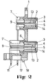
- a coaxial socket connector is shown in perspective view, which consists of a support body 1 made of plastic, in which two superimposed contact sleeves 2 are also injected. Inside each contact sleeve there is an insulating body insert 3, which consists of the same plastic as the supporting body. Insulating body insert 3 and supporting body are connected to one another by webs, which can have different shapes. For example, a first web 6, as can be seen from Figure 2, through an opening 8 in the contact sleeve from the support body to the insulator insert. Only one opening or several, as can be seen from FIG. 4, can be distributed over the circumference. The shape of the opening is of minor importance.
- the contact sleeves made of metal are first inserted and positioned in the injection mold.
- the support body and the insulating body insert are then shaped around the contact sleeves, the first webs being naturally formed simultaneously through the opening 8. This gives you a positive and positive connection.
- FIG. 1 Another type of webs is designated in FIG. 1 by 7 or 7 '.
- the second web 7 leads from the supporting body 1 over the edge of the contact sleeve 2 to the insulating body insert 3.
- Both types of webs can be present at the same time, but the solution is also conceivable in which either only one or only the other type is available .
- a central opening 4 in which an internal contact 5 is located is recessed in the insulator insert.
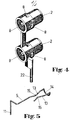
- This inner contact, together with its connecting lug 11, is made in one piece from wire, as can be seen from FIG.
- the connecting lug 11 is followed by approximately two parallel sections 13 which are connected to one another by an arcuate connecting part 14 which extends perpendicular to the sections. Approximately in the middle of the sections 13, these bends 15 have an obtuse angle. Since the internal contact with its sections 13 for positioning in recesses 12 lies in the insulator insert 3, the reversal points of the bends 15 protrude into the central opening 4. These reversal points and the connecting part 14 make the contact represent for a plug to be introduced, not shown.
- the recesses 12 in the insulator insert in which the internal contact lies are continued in the second webs 7 and 7 'in slots 9. These slots are located on the inside of the webs as well as on the front. The internal contact or the transition from the sections 13 to the connecting lug 11 is guided in them. This has the advantage that, in addition to easier assembly, good and safe insulation between the contact sleeve and the internal contact is also achieved at the same time. On the back of the webs, these have extensive depressions in which the connecting lugs are located.
- the socket connection is suitable for installation in a printed circuit, not shown.
- the support body is L-shaped, the shorter part coming as a base plate 17 on the surface of the printed circuit.
- a protruding pin 18 is also formed on the underside, which protrudes into a corresponding hole in the printed circuit.
- the support body can be secured by an additional screw connection if necessary.
- the connection lugs 11 of the internal contact and also that of the contact piece 16 are fixed in the base plate 17 in such a way that they are snapped into receptacles 20.
- the distance between these connections is 2.54 mm.
- the coaxial socket connector can be made both as a single connector and as a multiple arrangement.
- a double socket with two superimposed contact sleeves is shown as an embodiment.
- more than two contact sleeves are arranged one above the other.
- the edge of the support body can be provided with grooves and tongues, not shown in the figures, which enable aligned alignment.
- the exemplary embodiment shown in FIG. 1 has stepped edges 21 which overlap one another in the case of two supporting bodies lying close together.
- the connection itself can e.g. done by gluing.
- edges 19 which run on both sides at the rank of the support body and which abut one another in the case of adjacent support bodies and serve as energy direction transmitters in the ultrasound welding.
- two contact sleeves 2 are electrically connected to one another by a welded-on contact piece 16.
- FIG. 4 Another embodiment is shown in Figure 4.
- the contact sleeves and the connections between the two are made in one piece.
- the exemplary embodiments described so far and shown in the figures, in which the support body is L-shaped, are intended for use in a printed circuit.
- the support body is also possible to design the support body only in the form of a plate for other purposes.
- the inner contact made of wire expediently has soldering lugs as soldering lugs for soldering connecting wires.
Landscapes
- Coupling Device And Connection With Printed Circuit (AREA)
- Multi-Conductor Connections (AREA)
- Manufacturing Of Electrical Connectors (AREA)
Description
- Die Erfindung geht von einer koaxialen Buchsensteckverbindung nach dem Oberbegriff des Anspruches 1 aus
- Derartige koaxiale Buchsensteckverbindungen werden in Geräten der Unterhaltungsindustrie, z.B. in HiFi-Anlagen, zur Übertragung von Tonfrequenzen verwendet. Ferner können sie bei Lehrsystemen mit einem Einplatinen-Rechner oder auch bei Maschinensteuerungen eingesetzt werden. Ein weiteres Einsatzgebiet ist die Videotechnik.
- Aus der DE-A-25 47 951 ist bereits eine Stekkerbuchse bekannt, bei der ein von einer metallischen Abschirmkappe umgebener Isolierkörper in eine gedruckte Schaltung mittels U-förmiger Stützlappen eingesetzt ist. Der Isolierkörper aus Kunststoff weist eine Mittelöffnung auf, in die eine als Innenkontakt ausgebildete und aus einem ebenen Blechformteil hergestellte Kontakthülse mit Spiel gehalten wird. Diese Kontakthülse stützt sich zur axialen Fixierung mittels Anbiegungen auf einem stirnseitigen Ende des Isolierkörpers ab. Ferner hinterlassen nach aussen abgespreizte Federzungen der Kontakthülse eine sich an der Mittelöffnung anschliessende Absetzung. Die Kontakthülse ist mit einer als Lötanschluss dienenden Anschlussfahne versehen. Da die Steckerbuchse in eine Öffnung der gedruckten Schaltung eingesetzt wird, ist die Steckverbindung senkrecht zur gedruckten Schaltung.
- Eine Mehrfachanordnung einer als Cinch-Steckverbindung bezeichneten koaxialen Buchsensteckverbindung ist bereits aus der Zeitschrift «Asian Sources Electronics Components» September 1980 S. 346 bekannt, bei der die Steckrichtung parallel zu der gedruckten Schaltung erfolgt. In einem Tragkörper aus Kunststoff ist eine Kontakthülse aus Metall als Aussenkontakt gehaltert. Diese Kontakthülse besitzt eine nach unten gebogene Anschlussfahne. In diese Kontakthülse eingesetzt ist ein Isolierkörpereinsatz, der einen zentralen Durchbruch aufweist. Im Durchbruch befindet sich der Innenkontakt, dessen Anschlussfahne ebenfalls nach unten abgebogen ist.
- Aufgabe der vorliegenden Erfindung ist es, eine koaxiale Buchsensteckverbindung nach der eingangs genannten Art zu schaffen, die aus weniger getrennt hergestellten Einzelteilen besteht und die daher kostengünstiger gefertigt werden kann.
- Diese Aufgabe wird durch die im kennzeichnenden Teil des Patentanspruches 1 angegebenen Merkmale gelöst.
- Weitere vorteilhafte Ausgestaltungen der Erfindung sind den Unteransprüchen zu entnehmen.
- Durch die gleichzeitige Einspritzung des Isolierkörpereinsatzes zusammen mit der Kontakthülse an den Tragkörper wird so der Zeitaufwand für eine gesonderte Herstellung des Isolierkörpereinsatzes eingespart. Ausserdem entfallen die Montagekosten für das Einsetzen und Befestigen sowohl der Kontakthülse am Tragkörper als auch des Isolierkörpereinsatzes in der Kontakthülse.
- Einzelheiten der Erfindung werden nachfolgend für zwei Beispiele anhand der Zeichnungen näher beschrieben.
-
- Figur 1 eine perspektivische Rückansicht der koaxialen Buchsensteckverbindung,
- Figur 2 eine Seitenansicht im Schnitt durch die Buchsensteckverbindung,
- Fiur 3 eine Draufsicht im Schnitt durch die Buchsensteckverbindung,
- Figur 4 eine perspektivische Ansicht zweier einstückig hergestellter Kontakthülsen,
- Figur 5 eine perspektivische Ansicht des Innenkontaktes.
- In Figur 1 ist in perspektivischer Ansicht eine koaxiale Buchsensteckverbindung dargestellt, die aus einem Tragkörper 1 aus Kunststoff besteht, in dem in Mehrfachanordnung zwei übereinanderliegende Kontakthülsen 2 mit eingespritzt sind. Innerhalb jeder Kontakthülse befindet sich ein lsolierkörpereinsatz 3, der aus dem gleichen Kunststoff besteht, wie der Tragkörper. Isolierkörpereinsatz 3 und Tragkörper sind durch Stege miteinander verbunden, die unterschiedliche Formen aufweisen können. So erstreckt sich z.B. ein erster Steg 6, wie aus Figur 2 zu entnehmen ist, durch eine Öffnung 8 in der Kontakthülse vom Tragkörper zum Isolierkörpereinsatz. Es kann nur eine Öffnung oder es können auch mehrere, wie aus Figur 4 zu erkennen ist, am Umfang verteilt vorhanden sein. Die Form der Öffnung ist hierbei von untergeordneter Bedeutung.
- Bei der Herstellung der Buchsensteckverbindung werden zunächst die aus Metall hergestellten Kontakthülsen in das Spritzwerkzeug eingelegt und positioniert. Anschliessend werden dann der Tragkörper und der Isolierkörpereinsatz um die Kontakthülsen herum geformt, wobei natürlich gleichzeitig durch die Öffnung 8 die ersten Stege ausgebildet werden. Man erhält so eine kraft- und formschlüssige Verbindung.
- Eine andere Art der Stege ist in Figur 1 mit 7 bzw. 7' bezeichnet. Hier führt der zweite Steg 7 vom Tragkörper 1 über den Rand der Kontakthülse 2 hinweg zum Isolierkörpereinsatz 3. Es können zugleich beide Arten der Stege vorhanden sein, wobei jedoch auch die Lösung denkbar ist bei der entweder nur die eine oder nur die andere Art vorhanden ist.
- Im Isolierkörpereinsatz ist ein zentraler Durchbruch 4 ausgespart, in dem sich ein Innenkontakt 5 befindet. Dieser Innenkontakt ist zusammen mit seiner Anschlussfahne 11 einstückig aus Draht hergestellt, wie aus Figur 5 erkennbar ist. An die Anschlussfahne 11 schliessen sich etwa zwei parallel laufende Abschnitte 13 an, die durch ein sich senkrecht zu den Abschnitten erstreckendes, bogenförmiges Verbindungsteil 14 miteinander verbunden sind. Etwa in der Mitte der Abschnitte 13 weisen diese Abwinkelungen 15 einen stumpfen Winkel auf. Da der Innenkontakt mit seinen Abschnitten 13 zur Positionierung in Aussparungen 12 im Isolierkörpereinsatz 3 liegt, ragen die Umkehrpunkte der Abwinkelungen 15 in den zentralen Durchbruch 4. Diese Umkehrpunkte und der Verbindungsteil 14 stellen die Kontaktstellen für einen einzuführenden, nicht dargestellten Stecker dar.
- Die Aussparungen 12 im Isolierkörpereinsatz in den der Innenkontakt liegt, setzen sich in den zweiten Stegen 7 bzw. 7' in Schlitzen 9 fort. Diese Schlitze befinden sich sowohl auf der Innenseite der Stege als auch auf der Stirnseite. In ihnen ist der Innenkontakt bzw. der Obergang von den Abschnitten 13 zu der Anschlussfahne 11 geführt. Dies hat den Vorteil, dass neben einer leichteren Montage auch noch gleichzeitig eine gute und sichere Isolierung zwischen Kontakthülse und Innenkontakt erreicht wird. Auf der Rückseite der Stege besitzen diese flächenhafte Vertiefungen, in denen die Anschlussfahnen liegen. Wie aus Figur 1 zu erkennen ist, ist die Buchsenverbindung geeignet zum Einbau in eine nicht dargestellte gedruckte Schaltung. Zu diesem Zweck ist der Tragkörper L-förmig ausgebildet, wobei der kürzere Teil als Bodenplatte 17 auf der Oberfläche der gedruckten Schaltung zu liegen kommt. Zur genauen Positionierung ist auf der Unterseite noch ein vorstehender Zapfen 18 angeformt, der in ein entsprechendes Loch der gedruckten Schaltung hineinragt. Ausserdem kann der Tragkörper noch im Bedarfsfall durch eine zusätzliche Schraubverbindung gesichert werden. Die Festlegung der Anschlussfahnen 11 des Innenkontaktes und auch die des Kontaktstücks 16 in der Bodenplatte 17 erfolgt derart, dass diese in Aufnahmen 20 eingeschnappt werden. Selbstverständlich liegt der Abstand dieser Anschlüsse im Rastermass von 2,54 mm.
- Die koaxiale Buchsensteckverbindung kann sowohl als Einzelsteckverbindung als auch als Mehrfachanordnung hergestellt werden. In Figur 1 ist als ein Ausführungsbeispiel eine Doppelbuchse mit zwei übereinanderliegenden Kontakthülsen dargestellt. Es ist jedoch auch denkbar, dass mehr als zwei Kontakthülsen übereinander angeordnet sind. Ferner besteht noch die Möglichkeit, mehrere derartige Tragkörper nebeneinander zu einer Leiste zusammenzufügen. Hierzu kann der Rand des Tragkörpers mit in den Figuren nicht dargestellten Nuten und Federn versehen sein, die eine ausgerichtete Aneinanderreihung ermöglichen. Das in Figur 1 dargestellte Ausführungsbeispiel besitzt abgesetzte Ränder 21, die bei zwei dicht nebeneinanderliegenden Tragkörpern einander übergreifen. Die Verbindung selbst kann z.B. durch Kleben erfolgen. Es ist auch möglich, am Rang des Tragkörpers beidseitig verlaufende Kanten 19 vorzusehen, die bei benachbarten Tragkörpern aneinanderliegen und als Energierichtungsgeber bei der Ultraschallschweissung dienen.
- In der Ausführung als Doppelbuchse liegen zwei Kontakthülsen übereinander. In diesem Falle ist der untere zweite Steg 7' länger als der darüberliegende zweite Steg 7. Dies hat man deshalb so gewählt, um einen im Rastermass liegenden bestimmten Abstand der Anschlussfahnen der Innenkontakte zueinander zu erzielen. Auch hier liegt natürlich die Anschlussfahne des zweiten Steges 7' in der Vertiefung auf der Rückseite.
- Bei dem Ausführungsbeispiel in Figur 1 sind zwei Kontakthülsen 2 durch ein angeschweisstes Kontaktstück 16 elektrisch miteinander verbunden. Ein weiteres Ausführungsbeispiel ist in Figur 4 dargestellt. Hier sind im Gegensatz zu Figur 1 die Kontakthülsen und die Verbindungen zwischen beiden einstückig hergestellt. Selbstverständlich kann man auch gleichzeitig eine Anschlussfahne 22 mit anformen. Die restlichen Teile entsprechen denen der Figur 1.
- Die bislang beschriebenen und in den Figuren dargestellten Ausführungsbeispiele, bei denen der Tragkörper L-förmig ausgebildet ist, sind für den Einsatz in eine gedruckte Schaltung vorgesehen. Es ist jedoch auch möglich, für andere Verwendungszwecke den Tragkörper nur plattenförmig zu gestalten. Der aus Draht hergestellte Innenkontakt besitzt hierzu als Anschlussfahne zweckmässigerweise Lötösen zum Anlöten von Anschlussdrähten.
Claims (12)
Priority Applications (1)
| Application Number | Priority Date | Filing Date | Title |
|---|---|---|---|
| AT81107054T ATE8088T1 (de) | 1980-11-04 | 1981-09-08 | Koaxiale buchsensteckverbindung. |
Applications Claiming Priority (2)
| Application Number | Priority Date | Filing Date | Title |
|---|---|---|---|
| DE3041495 | 1980-11-04 | ||
| DE19803041495 DE3041495A1 (de) | 1980-11-04 | 1980-11-04 | Koaxiale buchsensteckverbindung |
Publications (2)
| Publication Number | Publication Date |
|---|---|
| EP0051130A1 EP0051130A1 (de) | 1982-05-12 |
| EP0051130B1 true EP0051130B1 (de) | 1984-06-20 |
Family
ID=6115887
Family Applications (1)
| Application Number | Title | Priority Date | Filing Date |
|---|---|---|---|
| EP81107054A Expired EP0051130B1 (de) | 1980-11-04 | 1981-09-08 | Koaxiale Buchsensteckverbindung |
Country Status (5)
| Country | Link |
|---|---|
| US (1) | US4431253A (de) |
| EP (1) | EP0051130B1 (de) |
| JP (1) | JPS57128474A (de) |
| AT (1) | ATE8088T1 (de) |
| DE (1) | DE3041495A1 (de) |
Families Citing this family (12)
| Publication number | Priority date | Publication date | Assignee | Title |
|---|---|---|---|---|
| US4548453A (en) * | 1983-03-11 | 1985-10-22 | Amp Incorporated | Right angle coaxial plug connector |
| US4603926A (en) * | 1983-12-29 | 1986-08-05 | Rca Corporation | Connector for joining microstrip transmission lines |
| USD302421S (en) | 1986-02-06 | 1989-07-25 | Hosiden Electronics Co., Ltd. | Connector socket |
| US4842527A (en) * | 1987-07-31 | 1989-06-27 | Motorola, Inc. | Contact assembly for interconnecting circuit board and a coaxial connector |
| JP2626477B2 (ja) * | 1993-07-08 | 1997-07-02 | 日本電気株式会社 | 同軸コネクタ |
| JP3071136B2 (ja) * | 1995-03-07 | 2000-07-31 | シャープ株式会社 | 端子構造ならびにこれを用いたユニバーサルlnb |
| DE29701944U1 (de) * | 1997-02-04 | 1997-04-03 | Rosenberger Hochfrequenztechnik GmbH & Co, 83413 Fridolfing | Koaxial-Steckverbinderbuchse |
| EP0893843A1 (de) * | 1997-07-21 | 1999-01-27 | Molex Incorporated | Modularer koaxialer Verbinder |
| US6358062B1 (en) * | 2000-10-24 | 2002-03-19 | 3M Innovative Properties Company | Coaxial connector assembly |
| JP2002164110A (ja) * | 2000-11-27 | 2002-06-07 | Jst Mfg Co Ltd | 高電圧用コネクタ |
| DE10123684A1 (de) * | 2001-05-15 | 2002-11-21 | Endress & Hauser Gmbh & Co Kg | Leiterplatte mit einer darauf aufgebrachten Kontakthülse |
| DE102015111543A1 (de) * | 2015-07-16 | 2017-01-19 | Phoenix Contact Gmbh & Co. Kg | Grundleiste zum Verbinden mit mindestens einem Steckverbinderteil |
Family Cites Families (13)
| Publication number | Priority date | Publication date | Assignee | Title |
|---|---|---|---|---|
| US1590823A (en) * | 1924-04-22 | 1926-06-29 | Simplex Electric Heating Compa | Electric connecter plug |
| DE485338C (de) * | 1929-01-12 | 1929-10-28 | Reklame Leuchtbau G M B H | Lichtreklamevorrichtung |
| GB914326A (en) * | 1958-04-16 | 1963-01-02 | Painton & Co Ltd | Improvements in or relating to coaxial electric plug and socket connectors |
| US3082395A (en) * | 1961-06-13 | 1963-03-19 | California Plasteck Inc | Electrical connector for illuminated panel |
| DE1591574A1 (de) * | 1967-09-29 | 1969-11-06 | Siemens Ag | Antennenverstaerkeranordnung mit nach dem Durchschleifverfahren miteinander verbundenen Koaxialbuchsen |
| US3564478A (en) * | 1968-05-06 | 1971-02-16 | Vm Corp | Electrical connector and ground structure |
| DE6800347U (de) * | 1968-10-02 | 1969-08-07 | Bosch Elektronik Photokino | Empfaengeranschlussvorrichtung |
| CA1009719A (en) * | 1973-01-29 | 1977-05-03 | Harold G. Hutter | Coaxial electrical connector |
| AU475619B2 (en) * | 1974-02-23 | 1976-08-26 | Yuko Shendosho Company Limited | pin PLUG |
| DD113136A1 (de) * | 1974-03-26 | 1975-05-12 | ||
| DE2547951A1 (de) * | 1975-10-27 | 1977-05-05 | Daut & Rietz Kg | Steckerbuchse |
| DE2729649C3 (de) * | 1977-06-30 | 1980-01-10 | Siemens Ag, 1000 Berlin Und 8000 Muenchen | Hochfrequenzdicht abgeschirmte Antennensteckdose mit einem Richtungskoppler |
| DE2841676A1 (de) * | 1978-09-25 | 1980-03-27 | Siemens Ag | Koaxiale steckbuchse |
-
1980
- 1980-11-04 DE DE19803041495 patent/DE3041495A1/de not_active Withdrawn
-
1981
- 1981-09-08 EP EP81107054A patent/EP0051130B1/de not_active Expired
- 1981-09-08 AT AT81107054T patent/ATE8088T1/de active
- 1981-10-28 US US06/315,752 patent/US4431253A/en not_active Expired - Fee Related
- 1981-11-04 JP JP56175843A patent/JPS57128474A/ja active Pending
Also Published As
| Publication number | Publication date |
|---|---|
| EP0051130A1 (de) | 1982-05-12 |
| JPS57128474A (en) | 1982-08-10 |
| ATE8088T1 (de) | 1984-07-15 |
| DE3041495A1 (de) | 1982-05-13 |
| US4431253A (en) | 1984-02-14 |
Similar Documents
| Publication | Publication Date | Title |
|---|---|---|
| DE69309309T2 (de) | Verbindungssystem | |
| DE69711716T2 (de) | Verbinderanordnung mit abgeschirmten modulen und verfahren für seine herstellung | |
| DE69619429T2 (de) | Hochleistungsfähiger Leiterplattenrandverbinder | |
| DE69619423T2 (de) | Abgeschirmter Verbinder mit einer Umhüllung, die mechanisch mit dem Gegenverbinder verbunden werden kann, ohne die Verbinderbreite zu erhöhen | |
| DE68927249T2 (de) | Steckverbindersystem für mehrere elektrische leiter | |
| DE3544838C2 (de) | ||
| DE2018376C3 (de) | Steckverteilertafel für koaxiale Steckverbindungen | |
| DE69413334T2 (de) | Elektrischer Erdungsverbinder | |
| DE69303201T2 (de) | Abgeschirmter Rückwandverbinder | |
| DE69214569T2 (de) | Elektrischer Verbinder zur Montage auf eine Leiterplatte | |
| DE19939580C2 (de) | Elektrischer Steckverbinder | |
| DE69330110T2 (de) | Elektrischer Verbinder mit verbesserten Kontaktrückhaltemitteln | |
| DE102014221070B4 (de) | Verbinderanschluss | |
| DE4309781A1 (de) | Elektrischer Verbinder | |
| DE69307217T2 (de) | Geschlechtlose Signal-Knoteneinheit mit zwei Enden | |
| DE69805463T2 (de) | Leiterplattenverbinder für Einpressmontage | |
| DE10119695B4 (de) | Steckverbinder für elektronische Bauelemente | |
| EP0051130B1 (de) | Koaxiale Buchsensteckverbindung | |
| DE2845632A1 (de) | Elektrisches verbindungselement | |
| DE112020006534T5 (de) | Abschirmverbinder | |
| EP0849840A2 (de) | Hochpoliger geschirmter Kabelstecker | |
| DE19918396C2 (de) | Verbinderanordnung für eine Leiterplatte | |
| DE69213991T2 (de) | Mehrfachkammer-Verbindermodul | |
| DE19835606C2 (de) | Abschirm-Steckverbinder | |
| DE68923361T2 (de) | Modulares Verbindersystem mit oberflächenmontierten Verbindern hoher Kontaktelementdichte. |
Legal Events
| Date | Code | Title | Description |
|---|---|---|---|
| PUAI | Public reference made under article 153(3) epc to a published international application that has entered the european phase |
Free format text: ORIGINAL CODE: 0009012 |
|
| AK | Designated contracting states |
Designated state(s): AT BE CH FR GB IT NL SE |
|
| 17P | Request for examination filed |
Effective date: 19820930 |
|
| ITF | It: translation for a ep patent filed | ||
| GRAA | (expected) grant |
Free format text: ORIGINAL CODE: 0009210 |
|
| AK | Designated contracting states |
Designated state(s): AT BE CH FR GB IT LI NL SE |
|
| REF | Corresponds to: |
Ref document number: 8088 Country of ref document: AT Date of ref document: 19840715 Kind code of ref document: T |
|
| PGFP | Annual fee paid to national office [announced via postgrant information from national office to epo] |
Ref country code: CH Payment date: 19840709 Year of fee payment: 4 |
|
| ET | Fr: translation filed | ||
| PGFP | Annual fee paid to national office [announced via postgrant information from national office to epo] |
Ref country code: FR Payment date: 19840918 Year of fee payment: 4 |
|
| PGFP | Annual fee paid to national office [announced via postgrant information from national office to epo] |
Ref country code: AT Payment date: 19840928 Year of fee payment: 4 |
|
| PGFP | Annual fee paid to national office [announced via postgrant information from national office to epo] |
Ref country code: SE Payment date: 19840930 Year of fee payment: 4 Ref country code: NL Payment date: 19840930 Year of fee payment: 4 Ref country code: BE Payment date: 19840930 Year of fee payment: 4 |
|
| PLBE | No opposition filed within time limit |
Free format text: ORIGINAL CODE: 0009261 |
|
| STAA | Information on the status of an ep patent application or granted ep patent |
Free format text: STATUS: NO OPPOSITION FILED WITHIN TIME LIMIT |
|
| 26N | No opposition filed | ||
| PG25 | Lapsed in a contracting state [announced via postgrant information from national office to epo] |
Ref country code: AT Effective date: 19850908 |
|
| PG25 | Lapsed in a contracting state [announced via postgrant information from national office to epo] |
Ref country code: SE Effective date: 19850909 |
|
| PG25 | Lapsed in a contracting state [announced via postgrant information from national office to epo] |
Ref country code: LI Effective date: 19850930 Ref country code: CH Effective date: 19850930 Ref country code: BE Effective date: 19850930 |
|
| BERE | Be: lapsed |
Owner name: PREH ELEKTROFEINMECHANISCHE WERKE JAKOB PREH NACH Effective date: 19850908 |
|
| PG25 | Lapsed in a contracting state [announced via postgrant information from national office to epo] |
Ref country code: NL Effective date: 19860401 |
|
| NLV4 | Nl: lapsed or anulled due to non-payment of the annual fee | ||
| PG25 | Lapsed in a contracting state [announced via postgrant information from national office to epo] |
Ref country code: FR Free format text: LAPSE BECAUSE OF NON-PAYMENT OF DUE FEES Effective date: 19860530 |
|
| REG | Reference to a national code |
Ref country code: CH Ref legal event code: PL |
|
| REG | Reference to a national code |
Ref country code: FR Ref legal event code: ST |
|
| GBPC | Gb: european patent ceased through non-payment of renewal fee | ||
| PG25 | Lapsed in a contracting state [announced via postgrant information from national office to epo] |
Ref country code: GB Effective date: 19881118 |
|
| EUG | Se: european patent has lapsed |
Ref document number: 81107054.9 Effective date: 19860729 |