EP0051132A1 - Erzeuger von Flüssigkeitströpfchen - Google Patents
Erzeuger von Flüssigkeitströpfchen Download PDFInfo
- Publication number
- EP0051132A1 EP0051132A1 EP81107083A EP81107083A EP0051132A1 EP 0051132 A1 EP0051132 A1 EP 0051132A1 EP 81107083 A EP81107083 A EP 81107083A EP 81107083 A EP81107083 A EP 81107083A EP 0051132 A1 EP0051132 A1 EP 0051132A1
- Authority
- EP
- European Patent Office
- Prior art keywords
- cavity
- generator
- ink
- liquid
- piezo
- Prior art date
- Legal status (The legal status is an assumption and is not a legal conclusion. Google has not performed a legal analysis and makes no representation as to the accuracy of the status listed.)
- Granted
Links
- 239000007788 liquid Substances 0.000 title claims abstract description 28
- 239000000463 material Substances 0.000 claims description 3
- 238000006073 displacement reaction Methods 0.000 claims description 2
- 239000002305 electric material Substances 0.000 claims 1
- 239000012858 resilient material Substances 0.000 claims 1
- 239000013078 crystal Substances 0.000 abstract description 41
- 238000007789 sealing Methods 0.000 abstract 1
- 239000012530 fluid Substances 0.000 description 13
- 238000007639 printing Methods 0.000 description 8
- 239000004809 Teflon Substances 0.000 description 3
- 229920006362 Teflon® Polymers 0.000 description 3
- 230000005284 excitation Effects 0.000 description 3
- 239000004593 Epoxy Substances 0.000 description 2
- 230000015556 catabolic process Effects 0.000 description 2
- 150000001875 compounds Chemical class 0.000 description 2
- 239000004020 conductor Substances 0.000 description 2
- 238000006731 degradation reaction Methods 0.000 description 2
- 238000007641 inkjet printing Methods 0.000 description 2
- 239000004727 Noryl Substances 0.000 description 1
- 229920001207 Noryl Polymers 0.000 description 1
- NIXOWILDQLNWCW-UHFFFAOYSA-N acrylic acid group Chemical group C(C=C)(=O)O NIXOWILDQLNWCW-UHFFFAOYSA-N 0.000 description 1
- 230000009977 dual effect Effects 0.000 description 1
- 230000001939 inductive effect Effects 0.000 description 1
- 238000004519 manufacturing process Methods 0.000 description 1
- 230000000737 periodic effect Effects 0.000 description 1
Images


Classifications
-
- B—PERFORMING OPERATIONS; TRANSPORTING
- B41—PRINTING; LINING MACHINES; TYPEWRITERS; STAMPS
- B41J—TYPEWRITERS; SELECTIVE PRINTING MECHANISMS, i.e. MECHANISMS PRINTING OTHERWISE THAN FROM A FORME; CORRECTION OF TYPOGRAPHICAL ERRORS
- B41J2/00—Typewriters or selective printing mechanisms characterised by the printing or marking process for which they are designed
- B41J2/005—Typewriters or selective printing mechanisms characterised by the printing or marking process for which they are designed characterised by bringing liquid or particles selectively into contact with a printing material
- B41J2/01—Ink jet
- B41J2/015—Ink jet characterised by the jet generation process
- B41J2/02—Ink jet characterised by the jet generation process generating a continuous ink jet
- B41J2/025—Ink jet characterised by the jet generation process generating a continuous ink jet by vibration
Definitions
- the invention relates to liquid droplet generators and is particularly concerned with such generators which are used to generate uniform droplets used for printing on a recording surface.
- a pressurized volume of print fluid such as ink is supplied into the ink receiving cavity of a drop generator.
- the ink is extruded as one or more capillary streams through one or more orifices coupled to the ink receiving cavity.
- a crystal which is disposed relative to the ink cavity is excited and creates a perturbation so that the streams are broken up into a plurality of droplets.
- the droplets are then controlled for writing on a recording surface.
- the droplets produced from the steams passing through each of the nozzles have substantially the same break-off point, be substantially uniform in size, have substantially uniform spacing between the droplets, and be satellite-free. This ensures that the quality of the print from each of the nozzles will be substantially the same.
- the perturbations applied to each of the ink streams of the nozzles be substantially uniform and that the nozzles be of uniform quality. Furthermore, for the production of the droplets to be satellite-free, it is necessary that the perturbations be sufficiently large. It also is necessary for the perturbations to not only be substantially uniform but to be reproducible throughout the time that the droplets are being produced.
- the transducer or driver which produces the vibrations for causing the perturbations in the ink streams, be capable of operation so that the amplitude of each of the pressure waves produced in the ink cavity by the driver is substantially the same at the entrance to each of the ink jet nozzles. This will produce uniform perturbations in the ink jet streams flowing through the nozzles. It also is necessary for the amplitude of the pressure waves to be sufficiently high to produce satellite-free droplets.
- U.S. Patent 4,153,901 (White) describes a multinozzle drop generator wherein a hemicylindrical or half cylinder crystal is used to create the disturbance.
- the drop generator consists of a carrier base or back plate in which an ink cavity and ink supply lines are fitted.
- the cavity is filled with a layer of resonance attenuating compound such as epoxy and Teflon.
- the teflon/epoxy layer is needed to attenuate unwanted resonances and reflections which affect the efficiency of the drop generator with frequency changes.
- the hemicylindrical crystal is mounted in the cavity with its concave surface facing upwardly.
- a gasket is fitted over the crystal and seals the cavity forming an ink chamber.
- a nozzle plate having a plurality of nozzles is then fitted over the gasket.
- a front plate with an elongated slot is fitted over the nozzle plate. The slot is aligned with the orifices. The components are held in position against the back plate by support screws.
- nonextendable means that neither the length of the nozzle array (that is the number of nozzles needed for printing) nor the drop frequency (that is the frequency used to drive the crystal) can be changed without undue degradation in the performance of the drop generator. Degradation includes nonuniform break-off of droplets, satellite problems, etc.
- the use of a resonating attenuating compound in the White drop generators tends to increase the overall cost of the drop generator and to limit the possible change of frequencies.
- the cost increase stems from increase in assembly time and the cost of the layer and the frequency limitation is inherent.
- U K specification No. 1591147 (DAS 28123720) describes a drop generator wherein a piezoelectric transducer forms a wall of an ink cavity, which has a linear array of ink jet nozzles communicating therewith.
- the piezoelectric transducer is preferably an arcuate sector of a cylinder having an angle no greater than 180o with its mean radius, wall thickness, and its arcuate angle selected so that the arcuate sector vibrates only in a selected symmetrical mode at a selected resonant frequency when a voltage is applied at that frequency.
- the length of the transducer is chosen to be longer than the length of the linear array of nozzles so that the periodic pressure waves produced in the ink cavity by the transducer vibrating at the selected resonant frequency will have substantially the same amplitude at the entrance of each of the nozzles to form droplets of substantially uniform size and at substantially the same break-off point.
- the applied voltage selected is that which is necessary to produce uniformly satellite-free droplets from the array of ink streams.
- European specification No. 111711 (US 4245225) describes a drop generator having an inner cylindrical tube spaced from an inner cylindrical surface of an outer means to have an ink cavity therebetween from which ink is supplied through one or more ink jet nozzles.
- a drop generator including a pair of radially expanding and contracting crystals are disposed diametrically to form opposite sides of a resonating cavity.
- the cavity is fitted with a conduit through which pressurized ink is supplied.
- a source of electrical signals are coupled to the crystals, they vibrate radially and emit pressure waves which reinforce themselves along a pressure line midway between the crystals.
- An elongated nozzle wafer carrying a linear row of orifices is disposed so that the center line of the orifices coincides with the pressure line and in fluidic communication with the cavity. Ink streams emanating through the orifices are broken up into droplets at a uniform distance from the nozzle wafer.
- the invention provides a liquid droplet generator comprising a cavity to which liquid under pressure is supplied and from which liquid exits as a series of parallel jets through a linear row of nozzles having their axes in a common plane and transducer means for establishing pressure perturbations in the liquid exiting from the cavity such as to cause the issuing liquid to break-up in droplets, characterised in that said transducer means comprise two elongate piezo-electric elements disposed on opposite sides of the common plane parallel thereto and arranged in operation to project pressure waves towards the common plane, the elements being at relative spacings from the plane such that the pressure waves reinforce each other at the common plane to create a maximum displacement thereat.
- the crystals are segmented whereby a longer head drop generator can be designed with uniform drive over the length of the crystal and the associated line of nozzle.
- each generator outputs a plurality of liquid jets which break up into streams of uniform droplets at a common point downstream from the nozzle plate.
- the drops may selectively be given an electrostatic charge upon break-off, and the charged drop subsequently deflect to a gutter, while the uncharged drops continue towards the recording medium for selectively printing data on the medium.
- the liquid comprises a magnetic writing ink
- the droplets may be selectively deflected by magnetic fields. Since both of these systems are well known in the art, details will not be given here. Suffice it to say that the showing in the figures may be used with either system.
- liquid jets issuing from nozzle orifices, tend to become unstable and break into droplets at different points from the nozzle plate.
- Practical uses of droplets for purposes such as printing dictates that break-off be uniform across each nozzle.
- the system that is the drop generator
- the drive voltage break-off distance usually remains in acceptable range. Any changes in drive voltage or frequency tend to cause break-off at different points downstream from the nozzle plate.
- prior art drop generators usually operate within a single frequency and voltage level.
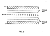
- FIG. 1 is a graphical representation showing the intended orientation for the perturbation means 10 and 12, hereinafter called crystals 10 and 12, and the nozzle orifices 14.
- the crystals 10 and 12 are disposed opposite to one another and the nozzle wafer containing the nozzle orifices 14 is disposed intermediate the crystals.
- the two crystals 10 and 12 are preferrably planar crystals polarized in the same direction and with their longitudinal axis running parallel to each other.
- One preferable configuration is that the crystals are placed equal distance from the plane running through the center of the nozzles 14 and containing the nozzle axes. Stated another way, the crystals are displaced in spaced relation and at right angles to the nozzle jets.
- the crystals When an excitation source is coupled to the crystals, the crystals expand and contract radially and send out pressure waves which meet and reinforce intermediate said crystals. Since the nozzle jet is disposed along the line of increase pressure waves, a wideband print window with excellent uniformity of break-off is obtained.
- Table 1 gives data of results obtained when a head fabricated in accordance with the conceptual showing of FIG. 1 was run in an actual ink jet printer.
- the first column represents the stream number.
- the number 23 means that the head that was run has 23 nozzles.
- the second column represents the crystal drive voltage and the drop frequency.
- the third column represents a second drive voltage and a second drop frequency at which the head was run.
- the fourth column shows still another drive voltage and drop frequency at which the same head was run.
- the break-off distance for the head at any particular voltage and frequency over a range of say 10 kilohertz was within + l/8 ⁇ . As such, this proves that by fabricating a drop generator in accordance with the teaching of the invention, wideband operation with uniform break-off and uniform drop size can be achieved without loss of other performance.
- FIG. 2 an exploded view of a print head according to the present invention is shown.
- FIG. 3 shows a cross-section taken across the head of FIG. 2.
- the liquid drop generator 16 includes a nozzle support member 18.
- a fluid cavity 20 is fabricated on the back surface of nozzle support member 18.
- the function of the cavity 20 is to hold printing fluid such as conductive ink, etc. Fluid is supplied into the cavity through conduit 22.
- the conduit in turn, is connected to pressure fluid supply source (not shown).
- a plurality of linearly spaced orifices 24 are formed in a nozzle wafer 26.
- the nozzle wafer, with the orifice, is then mounted on the front surface of nozzle support member 18.
- the mounting is such that the orifices communicate or interconnect with the cavity in the back surface with the front surface.
- a narrow slit is cut through support member 18 along line 28.
- the length of the slit depends on the length of the nozzle plate. Stated another way, the length of the slit is equivalent to the number of orifices which will be generating streams.
- the depth of the slit is such that the cavity in the back is connected to the front surface.
- the nozzle plate, with the orifices, is then seated on the slit so that the center of each hole is in fluidic communication with the cavity.
- the cavity has a cross-sectional V shape.
- the apex of the V coincides with the slot which interconnects the cavity to the front surface.
- the V acts as a focusing channel for directing the ink into the slot.
- a gasket 30 is fabricated with an opening in its central portion. The size of the opening is such that it surrounds the periphery of the cavity. The gasket is then disposed relative to the nozzle support member 18. The function of the gasket is to prevent ink or print fluid from escaping from the assembly.
- a crystal holder 32 is disposed next to the gasket 30.
- the crystal holder is fabricated with a central opening.
- the central opening is preferably wider than the central opening of the cavity.
- a pair of elongate piezo-electric crystals 34 and 36 are mounted on opposite walls of the crystal holder.
- the crystals are disposed diametrically on opposite walls of the crystal holder. The positioning is such that when all the components of the liquid drop generator 16 form a unitary structure, the crystals form opposite walls of the liquid cavity 20.
- a pair of holes are drilled into opposite walls of the crystal holder so that conductors 38 and 40 are connected to the crystal. Conductors 38 and 40 are coupled to an excitation source 47.
- the excitation source generates electrical signals for operating the crystals so that the capillary streams emanating from orifices 24 are broken up at a uniform distance from the nozzle plate.
- Another gasket 42 is disposed over crystal holder 32. An opening is fabricated in the central portion of gasket 42. The opening is such that it surrounds the cavity which is formed to contain the printing ink. The function of the gasket is to prevent ink from leaking out of the assembly.
- a back plate 44 is disposed next to gasket 42. The back plate closes the back of the cavity.
- a plurality of holes are drilled in the periphery of each component, and a plurality of screws (not shown) are used to fasten the component onto the nozzle support member or together to form a unified structure.
- FIGS. 4 and 5 show a second embodiment of a drop generator according to the present invention.
- the perturbation piezo-electric crystals 46 and 48 are not in contact with the printing ink as in the embodiment of FIGS. 2 and 3.
- Common elements in FIGS. 4 and 5 will be identified with the same numeral.
- FIG. 4 is a perspective view of the second embodiment while FIG. 5 is a cross-section of FIG. 4.
- the drop generator 50 includes a nozzle support member 52 having an ink containing cavity 54, with a focusing cavity 56, disposed in one surface.
- the ink containing cavity 54 is formed by the rectangular side and end walls of the nozzle support member.
- the focusing cavity 56 guides a narrow volume of ink into a plurality of nozzle orifices 58 in a nozzle plate 26 mounted on the surface of the nozzle support member 52 opposite the ink containing cavity and the focus cavity, respectively.
- ink under pressure is pumped through conduit 60 into the ink containing cavity.
- a closure means 62 is disposed upon the upwardly extending rectangular walls of the nozzle support member.
- the closure member means 62 includes a plurality of strips contiguously disposed in juxtaposition relative to one another.
- a central strip 64 is fabricated with dimensions large enough to cover the back opening of ink containing cavity 54. Crystals 46 and 48 are disposed on opposite sides of member 64. The crystals extend in parallel direction along the lengthwise dimension of the member 64.
- the member 64 With the member 64 of a sufficient dimension to cover the ink containing cavity 54, when ink is pumped into the cavity, the ink does not contact either of the perturbation crystals.
- the member 64 can be regarded as a wave guide acting to transmit pressure waves from the crystal bars 46, 48 to the fluid in the cavity 54.
- the wave transmitting characteristic of the member 64 should be selected to match those of the fluid (or vice versa).
- Several types of material, including noryl, PVC, acrylic and teflon can be used.
- the members 64, 66, 68 are formed of the same material.
- a back plate 70 is then disposed upon the closure member means 62.
- a gasket (not shown) with a central opening can be introduced between nozzle support member 52 and closure member means 62 to contain the ink within the containing cavity. Any suitable means including screws, etc., can be used for fastening the assembly.
- the length dimension of both the transducers and the ink cavity is parallel to a line connecting the entrances of the nozzles of the array to the cavity.
- the required transducers vibration mode which produces uniform perturbations for the array of ink jet streams is that in which the vibrations are in phase along a line intermediate the crystals and run or act along the lengthwise direction of the transducers, and in which the amplitudes are uniform over the transducer length.
- a liquid drop generator (16) including a liquid supply line (22) connected to a source of pressurized ink, an ink supply cavity (20) for accepting the pressurized ink, a nozzle plate (26) with orifices (24) for generating capillary streams from the ink supply cavity, and a signal input (47) connected to a perturbation signal source, said generator further comprising a pair of perturbation means (34; 36) spaced diametrically to form part of the side walls of the ink supply cavity; said perturbation means being operable to generate a reinforceable pressure zone; and said nozzle plate comprising an elongated nozzle wafer having a row or line of linear orifices therethrough disposed so that the center lines of said orifices are each positioned on the pressure zone.
Landscapes
- Particle Formation And Scattering Control In Inkjet Printers (AREA)
Applications Claiming Priority (2)
| Application Number | Priority Date | Filing Date | Title |
|---|---|---|---|
| US203089 | 1980-11-03 | ||
| US06/203,089 US4354194A (en) | 1980-11-03 | 1980-11-03 | Wideband ink drop generator |
Publications (2)
| Publication Number | Publication Date |
|---|---|
| EP0051132A1 true EP0051132A1 (de) | 1982-05-12 |
| EP0051132B1 EP0051132B1 (de) | 1984-12-12 |
Family
ID=22752459
Family Applications (1)
| Application Number | Title | Priority Date | Filing Date |
|---|---|---|---|
| EP81107083A Expired EP0051132B1 (de) | 1980-11-03 | 1981-09-09 | Erzeuger von Flüssigkeitströpfchen |
Country Status (4)
| Country | Link |
|---|---|
| US (1) | US4354194A (de) |
| EP (1) | EP0051132B1 (de) |
| JP (1) | JPS5784861A (de) |
| DE (1) | DE3167720D1 (de) |
Cited By (2)
| Publication number | Priority date | Publication date | Assignee | Title |
|---|---|---|---|---|
| EP0805026A1 (de) * | 1996-04-30 | 1997-11-05 | SCITEX DIGITAL PRINTING, Inc. | Hartlötverfahren für einen kontinuierlich arbeitenden Tintenstrahldrucker |
| US6536881B1 (en) * | 1996-08-28 | 2003-03-25 | Marconi Data Systems Inc. | Continuous stream ink jet print head droplet generator having backing member bridging divided vibrator |
Families Citing this family (3)
| Publication number | Priority date | Publication date | Assignee | Title |
|---|---|---|---|---|
| DE3306098A1 (de) * | 1983-02-22 | 1984-08-23 | Siemens AG, 1000 Berlin und 8000 München | Piezoelektrisch betriebener schreibkopf mit kanalmatrize |
| US4554558A (en) * | 1983-05-19 | 1985-11-19 | The Mead Corporation | Fluid jet print head |
| US4935750A (en) * | 1989-08-31 | 1990-06-19 | Xerox Corporation | Sealing means for thermal ink jet printheads |
Family Cites Families (8)
| Publication number | Priority date | Publication date | Assignee | Title |
|---|---|---|---|---|
| US3334351A (en) * | 1965-06-16 | 1967-08-01 | Honeywell Inc | Ink droplet recorder with plural nozzle-vibrators |
| US3958249A (en) * | 1974-12-18 | 1976-05-18 | International Business Machines Corporation | Ink jet drop generator |
| US4153901A (en) * | 1976-12-20 | 1979-05-08 | Recognition Equipment Incorporated | Variable frequency multi-orifice IJP |
| US4303927A (en) * | 1977-03-23 | 1981-12-01 | International Business Machines Corporation | Apparatus for exciting an array of ink jet nozzles and method of forming |
| JPS592617B2 (ja) * | 1977-12-22 | 1984-01-19 | 株式会社リコー | インク噴射装置 |
| JPS54159228A (en) * | 1978-06-07 | 1979-12-15 | Ricoh Co Ltd | Method and apparatus for ink jet recording |
| US4245225A (en) * | 1978-11-08 | 1981-01-13 | International Business Machines Corporation | Ink jet head |
| US4245227A (en) * | 1978-11-08 | 1981-01-13 | International Business Machines Corporation | Ink jet head having an outer wall of ink cavity of piezoelectric material |
-
1980
- 1980-11-03 US US06/203,089 patent/US4354194A/en not_active Expired - Lifetime
-
1981
- 1981-07-31 JP JP56119445A patent/JPS5784861A/ja active Pending
- 1981-09-09 DE DE8181107083T patent/DE3167720D1/de not_active Expired
- 1981-09-09 EP EP81107083A patent/EP0051132B1/de not_active Expired
Non-Patent Citations (1)
| Title |
|---|
| No relevant documents have been disclosed. * |
Cited By (3)
| Publication number | Priority date | Publication date | Assignee | Title |
|---|---|---|---|---|
| EP0805026A1 (de) * | 1996-04-30 | 1997-11-05 | SCITEX DIGITAL PRINTING, Inc. | Hartlötverfahren für einen kontinuierlich arbeitenden Tintenstrahldrucker |
| AU716068B2 (en) * | 1996-04-30 | 2000-02-17 | Scitex Digital Printing, Inc. | Brazing process for a continuous ink jet printhead |
| US6536881B1 (en) * | 1996-08-28 | 2003-03-25 | Marconi Data Systems Inc. | Continuous stream ink jet print head droplet generator having backing member bridging divided vibrator |
Also Published As
| Publication number | Publication date |
|---|---|
| JPS5784861A (en) | 1982-05-27 |
| DE3167720D1 (en) | 1985-01-24 |
| US4354194A (en) | 1982-10-12 |
| EP0051132B1 (de) | 1984-12-12 |
Similar Documents
| Publication | Publication Date | Title |
|---|---|---|
| US4138687A (en) | Apparatus for producing multiple uniform fluid filaments and drops | |
| US4303927A (en) | Apparatus for exciting an array of ink jet nozzles and method of forming | |
| US4703333A (en) | Impulse ink jet print head with inclined and stacked arrays | |
| US4370662A (en) | Ink jet array ultrasonic simulation | |
| EP0461238B1 (de) | Synchronierte erregung für kontinuierlich arbeitenden tintenstrahldrucker mit einer langen reihe von düsen | |
| SU878211A3 (ru) | Устройство дл формировани потоков жидкостных капель в блоках струйной печати | |
| EP0011171B1 (de) | Vorrichtung zum Erzeugen von Flüssigkeitströpfchen | |
| US4245227A (en) | Ink jet head having an outer wall of ink cavity of piezoelectric material | |
| US5363131A (en) | Ink jet recording head | |
| GB2094233A (en) | Ink jet apparatus | |
| US4188635A (en) | Ink jet printing head | |
| US4587528A (en) | Fluid jet print head having resonant cavity | |
| US4788557A (en) | Ink jet method and apparatus for reducing cross talk | |
| EP0051132B1 (de) | Erzeuger von Flüssigkeitströpfchen | |
| US4958168A (en) | Inkjet drop generator | |
| KR100332142B1 (ko) | 잉크젯어레이 | |
| US4528571A (en) | Fluid jet print head having baffle means therefor | |
| US7033003B2 (en) | Continuous stream binary array ink jet print head | |
| US4153901A (en) | Variable frequency multi-orifice IJP | |
| JPH03500753A (ja) | 改良励振導波部材構造を有する連続インクジェットプリンタ | |
| US3960324A (en) | Method for generation of multiple uniform fluid filaments | |
| US4326206A (en) | Method of reducing cross talk in ink jet arrays | |
| EP0260884B1 (de) | Druckkopf für Tintenstrahldrucker nach der gesteuerten Tröpfchenerzeugungsart | |
| US4065774A (en) | Hybrid fluid jet drop generation | |
| EP1800866B1 (de) | Tröpfchengenerator und Tintenstrahlaufzeichnungsvorrichtung |
Legal Events
| Date | Code | Title | Description |
|---|---|---|---|
| PUAI | Public reference made under article 153(3) epc to a published international application that has entered the european phase |
Free format text: ORIGINAL CODE: 0009012 |
|
| 17P | Request for examination filed |
Effective date: 19810909 |
|
| AK | Designated contracting states |
Designated state(s): DE FR GB IT |
|
| GRAA | (expected) grant |
Free format text: ORIGINAL CODE: 0009210 |
|
| AK | Designated contracting states |
Designated state(s): DE FR GB IT |
|
| PG25 | Lapsed in a contracting state [announced via postgrant information from national office to epo] |
Ref country code: IT Free format text: LAPSE BECAUSE OF FAILURE TO SUBMIT A TRANSLATION OF THE DESCRIPTION OR TO PAY THE FEE WITHIN THE PRESCRIBED TIME-LIMIT;WARNING: LAPSES OF ITALIAN PATENTS WITH EFFECTIVE DATE BEFORE 2007 MAY HAVE OCCURRED AT ANY TIME BEFORE 2007. THE CORRECT EFFECTIVE DATE MAY BE DIFFERENT FROM THE ONE RECORDED. Effective date: 19841212 |
|
| REF | Corresponds to: |
Ref document number: 3167720 Country of ref document: DE Date of ref document: 19850124 |
|
| ET | Fr: translation filed | ||
| PLBE | No opposition filed within time limit |
Free format text: ORIGINAL CODE: 0009261 |
|
| STAA | Information on the status of an ep patent application or granted ep patent |
Free format text: STATUS: NO OPPOSITION FILED WITHIN TIME LIMIT |
|
| 26N | No opposition filed | ||
| REG | Reference to a national code |
Ref country code: FR Ref legal event code: GC |
|
| REG | Reference to a national code |
Ref country code: GB Ref legal event code: 732 |
|
| REG | Reference to a national code |
Ref country code: FR Ref legal event code: TP |
|
| PGFP | Annual fee paid to national office [announced via postgrant information from national office to epo] |
Ref country code: FR Payment date: 19920812 Year of fee payment: 12 |
|
| PGFP | Annual fee paid to national office [announced via postgrant information from national office to epo] |
Ref country code: DE Payment date: 19920820 Year of fee payment: 12 |
|
| PGFP | Annual fee paid to national office [announced via postgrant information from national office to epo] |
Ref country code: GB Payment date: 19920826 Year of fee payment: 12 |
|
| PG25 | Lapsed in a contracting state [announced via postgrant information from national office to epo] |
Ref country code: GB Effective date: 19930909 |
|
| GBPC | Gb: european patent ceased through non-payment of renewal fee |
Effective date: 19930909 |
|
| PG25 | Lapsed in a contracting state [announced via postgrant information from national office to epo] |
Ref country code: FR Free format text: LAPSE BECAUSE OF NON-PAYMENT OF DUE FEES Effective date: 19940531 |
|
| PG25 | Lapsed in a contracting state [announced via postgrant information from national office to epo] |
Ref country code: DE Effective date: 19940601 |
|
| REG | Reference to a national code |
Ref country code: FR Ref legal event code: ST |