EP0051170A1 - Disposition d'étanchéité à lèvres axiales et radiales et à labyrinthe - Google Patents
Disposition d'étanchéité à lèvres axiales et radiales et à labyrinthe Download PDFInfo
- Publication number
- EP0051170A1 EP0051170A1 EP81108222A EP81108222A EP0051170A1 EP 0051170 A1 EP0051170 A1 EP 0051170A1 EP 81108222 A EP81108222 A EP 81108222A EP 81108222 A EP81108222 A EP 81108222A EP 0051170 A1 EP0051170 A1 EP 0051170A1
- Authority
- EP
- European Patent Office
- Prior art keywords
- annular
- fact
- sealing assembly
- members
- lip
- Prior art date
- Legal status (The legal status is an assumption and is not a legal conclusion. Google has not performed a legal analysis and makes no representation as to the accuracy of the status listed.)
- Withdrawn
Links
- 238000007789 sealing Methods 0.000 title claims abstract description 46
- 239000000314 lubricant Substances 0.000 claims abstract description 13
- 239000000463 material Substances 0.000 claims abstract description 13
- 239000000126 substance Substances 0.000 claims abstract description 5
- 230000000694 effects Effects 0.000 claims description 5
- 230000002093 peripheral effect Effects 0.000 claims description 2
- 239000007769 metal material Substances 0.000 claims 1
- 239000000356 contaminant Substances 0.000 description 6
- 238000005096 rolling process Methods 0.000 description 6
- 239000002184 metal Substances 0.000 description 5
- 229910052751 metal Inorganic materials 0.000 description 5
- 230000000712 assembly Effects 0.000 description 3
- 238000000429 assembly Methods 0.000 description 3
- 239000003795 chemical substances by application Substances 0.000 description 3
- 239000004519 grease Substances 0.000 description 3
- 125000006850 spacer group Chemical group 0.000 description 3
- 238000005119 centrifugation Methods 0.000 description 2
- 239000000470 constituent Substances 0.000 description 2
- 238000006073 displacement reaction Methods 0.000 description 2
- 239000013536 elastomeric material Substances 0.000 description 2
- 239000004033 plastic Substances 0.000 description 2
- 229920003023 plastic Polymers 0.000 description 2
- 230000002787 reinforcement Effects 0.000 description 2
- HCHKCACWOHOZIP-UHFFFAOYSA-N Zinc Chemical compound [Zn] HCHKCACWOHOZIP-UHFFFAOYSA-N 0.000 description 1
- 238000004026 adhesive bonding Methods 0.000 description 1
- 239000000428 dust Substances 0.000 description 1
- 239000012530 fluid Substances 0.000 description 1
- 230000004048 modification Effects 0.000 description 1
- 238000012986 modification Methods 0.000 description 1
- 238000007747 plating Methods 0.000 description 1
- 230000035939 shock Effects 0.000 description 1
- 239000007779 soft material Substances 0.000 description 1
- 238000003466 welding Methods 0.000 description 1
- 229910052725 zinc Inorganic materials 0.000 description 1
- 239000011701 zinc Substances 0.000 description 1
Images

Classifications
-
- F—MECHANICAL ENGINEERING; LIGHTING; HEATING; WEAPONS; BLASTING
- F16—ENGINEERING ELEMENTS AND UNITS; GENERAL MEASURES FOR PRODUCING AND MAINTAINING EFFECTIVE FUNCTIONING OF MACHINES OR INSTALLATIONS; THERMAL INSULATION IN GENERAL
- F16C—SHAFTS; FLEXIBLE SHAFTS; ELEMENTS OR CRANKSHAFT MECHANISMS; ROTARY BODIES OTHER THAN GEARING ELEMENTS; BEARINGS
- F16C33/00—Parts of bearings; Special methods for making bearings or parts thereof
- F16C33/72—Sealings
- F16C33/76—Sealings of ball or roller bearings
- F16C33/78—Sealings of ball or roller bearings with a diaphragm, disc, or ring, with or without resilient members
- F16C33/7869—Sealings of ball or roller bearings with a diaphragm, disc, or ring, with or without resilient members mounted with a cylindrical portion to the inner surface of the outer race and having a radial portion extending inward
- F16C33/7879—Sealings of ball or roller bearings with a diaphragm, disc, or ring, with or without resilient members mounted with a cylindrical portion to the inner surface of the outer race and having a radial portion extending inward with a further sealing ring
- F16C33/7883—Sealings of ball or roller bearings with a diaphragm, disc, or ring, with or without resilient members mounted with a cylindrical portion to the inner surface of the outer race and having a radial portion extending inward with a further sealing ring mounted to the inner race and of generally L-shape, the two sealing rings defining a sealing with box-shaped cross-section
-
- F—MECHANICAL ENGINEERING; LIGHTING; HEATING; WEAPONS; BLASTING
- F16—ENGINEERING ELEMENTS AND UNITS; GENERAL MEASURES FOR PRODUCING AND MAINTAINING EFFECTIVE FUNCTIONING OF MACHINES OR INSTALLATIONS; THERMAL INSULATION IN GENERAL
- F16J—PISTONS; CYLINDERS; SEALINGS
- F16J15/00—Sealings
- F16J15/16—Sealings between relatively-moving surfaces
- F16J15/32—Sealings between relatively-moving surfaces with elastic sealings, e.g. O-rings
- F16J15/3204—Sealings between relatively-moving surfaces with elastic sealings, e.g. O-rings with at least one lip
- F16J15/3232—Sealings between relatively-moving surfaces with elastic sealings, e.g. O-rings with at least one lip having two or more lips
-
- F—MECHANICAL ENGINEERING; LIGHTING; HEATING; WEAPONS; BLASTING
- F16—ENGINEERING ELEMENTS AND UNITS; GENERAL MEASURES FOR PRODUCING AND MAINTAINING EFFECTIVE FUNCTIONING OF MACHINES OR INSTALLATIONS; THERMAL INSULATION IN GENERAL
- F16J—PISTONS; CYLINDERS; SEALINGS
- F16J15/00—Sealings
- F16J15/16—Sealings between relatively-moving surfaces
- F16J15/32—Sealings between relatively-moving surfaces with elastic sealings, e.g. O-rings
- F16J15/3248—Sealings between relatively-moving surfaces with elastic sealings, e.g. O-rings provided with casings or supports
- F16J15/3252—Sealings between relatively-moving surfaces with elastic sealings, e.g. O-rings provided with casings or supports with rigid casings or supports
- F16J15/3256—Sealings between relatively-moving surfaces with elastic sealings, e.g. O-rings provided with casings or supports with rigid casings or supports comprising two casing or support elements, one attached to each surface, e.g. cartridge or cassette seals
- F16J15/3264—Sealings between relatively-moving surfaces with elastic sealings, e.g. O-rings provided with casings or supports with rigid casings or supports comprising two casing or support elements, one attached to each surface, e.g. cartridge or cassette seals the elements being separable from each other
-
- F—MECHANICAL ENGINEERING; LIGHTING; HEATING; WEAPONS; BLASTING
- F16—ENGINEERING ELEMENTS AND UNITS; GENERAL MEASURES FOR PRODUCING AND MAINTAINING EFFECTIVE FUNCTIONING OF MACHINES OR INSTALLATIONS; THERMAL INSULATION IN GENERAL
- F16C—SHAFTS; FLEXIBLE SHAFTS; ELEMENTS OR CRANKSHAFT MECHANISMS; ROTARY BODIES OTHER THAN GEARING ELEMENTS; BEARINGS
- F16C19/00—Bearings with rolling contact, for exclusively rotary movement
- F16C19/02—Bearings with rolling contact, for exclusively rotary movement with bearing balls essentially of the same size in one or more circular rows
- F16C19/14—Bearings with rolling contact, for exclusively rotary movement with bearing balls essentially of the same size in one or more circular rows for both radial and axial load
- F16C19/18—Bearings with rolling contact, for exclusively rotary movement with bearing balls essentially of the same size in one or more circular rows for both radial and axial load with two or more rows of balls
- F16C19/181—Bearings with rolling contact, for exclusively rotary movement with bearing balls essentially of the same size in one or more circular rows for both radial and axial load with two or more rows of balls with angular contact
- F16C19/183—Bearings with rolling contact, for exclusively rotary movement with bearing balls essentially of the same size in one or more circular rows for both radial and axial load with two or more rows of balls with angular contact with two rows at opposite angles
- F16C19/184—Bearings with rolling contact, for exclusively rotary movement with bearing balls essentially of the same size in one or more circular rows for both radial and axial load with two or more rows of balls with angular contact with two rows at opposite angles in O-arrangement
-
- F—MECHANICAL ENGINEERING; LIGHTING; HEATING; WEAPONS; BLASTING
- F16—ENGINEERING ELEMENTS AND UNITS; GENERAL MEASURES FOR PRODUCING AND MAINTAINING EFFECTIVE FUNCTIONING OF MACHINES OR INSTALLATIONS; THERMAL INSULATION IN GENERAL
- F16C—SHAFTS; FLEXIBLE SHAFTS; ELEMENTS OR CRANKSHAFT MECHANISMS; ROTARY BODIES OTHER THAN GEARING ELEMENTS; BEARINGS
- F16C19/00—Bearings with rolling contact, for exclusively rotary movement
- F16C19/22—Bearings with rolling contact, for exclusively rotary movement with bearing rollers essentially of the same size in one or more circular rows, e.g. needle bearings
- F16C19/34—Bearings with rolling contact, for exclusively rotary movement with bearing rollers essentially of the same size in one or more circular rows, e.g. needle bearings for both radial and axial load
- F16C19/38—Bearings with rolling contact, for exclusively rotary movement with bearing rollers essentially of the same size in one or more circular rows, e.g. needle bearings for both radial and axial load with two or more rows of rollers
- F16C19/383—Bearings with rolling contact, for exclusively rotary movement with bearing rollers essentially of the same size in one or more circular rows, e.g. needle bearings for both radial and axial load with two or more rows of rollers with tapered rollers, i.e. rollers having essentially the shape of a truncated cone
- F16C19/385—Bearings with rolling contact, for exclusively rotary movement with bearing rollers essentially of the same size in one or more circular rows, e.g. needle bearings for both radial and axial load with two or more rows of rollers with tapered rollers, i.e. rollers having essentially the shape of a truncated cone with two rows, i.e. double-row tapered roller bearings
- F16C19/386—Bearings with rolling contact, for exclusively rotary movement with bearing rollers essentially of the same size in one or more circular rows, e.g. needle bearings for both radial and axial load with two or more rows of rollers with tapered rollers, i.e. rollers having essentially the shape of a truncated cone with two rows, i.e. double-row tapered roller bearings in O-arrangement
Definitions
- the present invention relates to a sealing assembly which can be interposed between two members one of which is rotatable and the other of which is fixed, for example the rings of a rolling element bearing, and in particular to a sealing assembly of the two lip type.
- seals of various types there are used seals of various types, this latter term meaning assemblies including one or more sealing rings with suitable form, in one or more pieces, made of soft and reslilient material possibly with metal reinforcement and provided with parts which are carried in contact under predetermined pressure with the surface of the movable member to make a seal with it.
- a sealing assembly which can be interposed between two members between which there is a peripheral relative velocity to form a seal between a cavity between the said members and the external environment around the cavity itself, characterised by the fact that it comprises a first and a second annular element each of which can be mounted on one of the said members and rigidly connected thereto, the first of the said annular elements being provided with at least one pair of annular lips of resiliently deformable material the first of which extends in a direction substantially parallel to the axis of the said first element and a second of which extends in a direction substantially radial to the said axis, and the seccnd of the said annular elements being provided with at least a first and a second sliding surface which can come into contact with the said first and second lip respectively when the said elements are mounted on associated rotating members, in such a way that between each of the said lips and the associated sliding surfaces there is transmitted a predetermined pressure for preventing the passage of lubricant and contaminating substances between the said chamber and the
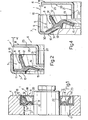
- a sealing assembly forming the subject of the present invention is interposed between a rotatable shaft 2 and an annular seat 3 coaxial to the shaft itself and formed on a base 4.
- the sealing assembly 1 ( Figure 2) is constituted by a sealing ring 5, which in the example of Figure 1 is secured in the seat 3, and by a rigid screen 6 which in the same example is secured to the shaft 2.
- the sealing ring 5 includes a support element 7 of annular form of metal or other rigid and highly resistant material onto which there is vulcanised or otherwise fixed, for example by means of welding or gluing a sealing element 8 made of a soft and resiliently deformable material, such as an elastomeric material, a rubber or a synthetic plastics material.
- the support element 7 hasanL-shape section with a first part 9 parallel to the axis of the shaft and second part 10 orthogonal to the other and extending radially towards the axis of the shaft.
- the ends 14 and 15 of the two lips 12 and 13 are formed in a manner such as to be able to slide respectively over the surfaces 20, 21 of the screen 6 which is constituted by a sleeve part 22 of suitable thickness and a flange part 23 perpendicular thereto and of external diameter such as to leave, once assembled, a predetermined play, indicated a between itself and the part 9 of the support element 7.
- the support element 7 can be rigidly lodged in a seat 3 formed in the base 4 to which it is coupled by means of part 9.
- the fixing of the sealing ring 5 and of the screen 6 to the seat 3 and the shaft 2 respectively can be effected in any convenient manner, for example by slightly forcing it as has been illustrated in Figure 1, or else by means of suitable fixing members and parts, such as shoulders, spacers, threaded rings, resilient rings and the like.
- the support element 7 has an annular structure with a first part 9 parallel to the axis of the said element identical to that of Figure 2, a second part 10 substantially orthogonal to the first, extending radially towards the axis mentioned above, and which after a first section 30 perpendicular to the part 9 has a second section 31 inclined by a predetermined angle which terminates with a further short section 32 parallel to the first section 30.
- the sealing element 8 on the other hand,includes a first substantially flat part 11 which follows the profile of the part 10 of the element 7 to which it is welded. From this part there extend two annular lips 12 and 13 identical to those illustrated in Figure 2.
- a conical roller bearing 33 comprising an outer ring 34, two inner half rings 35, spacer cages 36 and.roller bodies 37, the inner chamber 38 of which is protected by means of the interposition between the outer ring 34 and the inner half rings 35 of sealing assemblies 1.
- the sealing ring 5 is secured, thanks to the part 9, to the seat 3 formed on the base 4.
- the rigid screen 6 is mounted by pushing it along the shaft 2 until the flange part 23 comes edge to edge with the rim 16 of the part 9.
- the lips 12 and 13 are resiliently deformed because of their dimensions and form a sliding resilient seal by coming into contact with their ends 14 and 15 respectively against the surface 20 of the flange part 23 and the surface 21 of the sleeve part 22.
- the end 14 faces the external environment whilst the end 15 faces the inner chamber 17 delimited by the seat 3 and the shaft 2.
- the present invention provides a seal simultaneously and equally effective both against possible escape of lubricant and against external contaminants.
- the seals moreover, are positioned, one in a radial direction and the other in an axial direction so that a possible displacement in use, due for example to vibrations or shocks would entirely or partly eliminate only one of the said seals leaving the other perfectly effective, it being necessary to consider a simultaneous radial and axial displacement as being extremely improbable.
- the seal due to the pressure there is associated that due to the resistance opposed to the passage offered by the said labyrinth seal constituted by the gap and that caused by the centrifuging action of the rigid screen.
Landscapes
- Engineering & Computer Science (AREA)
- General Engineering & Computer Science (AREA)
- Mechanical Engineering (AREA)
- Sealing With Elastic Sealing Lips (AREA)
- Sealing Of Bearings (AREA)
- Sealing Using Fluids, Sealing Without Contact, And Removal Of Oil (AREA)
Applications Claiming Priority (2)
| Application Number | Priority Date | Filing Date | Title |
|---|---|---|---|
| IT68665/80A IT1129357B (it) | 1980-10-31 | 1980-10-31 | Complesso di tenuta comprendente due labbri uno assiale e l altro radiale ed un labirinto |
| IT6866580 | 1980-10-31 |
Publications (1)
| Publication Number | Publication Date |
|---|---|
| EP0051170A1 true EP0051170A1 (fr) | 1982-05-12 |
Family
ID=11310226
Family Applications (1)
| Application Number | Title | Priority Date | Filing Date |
|---|---|---|---|
| EP81108222A Withdrawn EP0051170A1 (fr) | 1980-10-31 | 1981-10-12 | Disposition d'étanchéité à lèvres axiales et radiales et à labyrinthe |
Country Status (4)
| Country | Link |
|---|---|
| EP (1) | EP0051170A1 (fr) |
| JP (1) | JPS57103930A (fr) |
| ES (1) | ES506748A0 (fr) |
| IT (1) | IT1129357B (fr) |
Cited By (13)
| Publication number | Priority date | Publication date | Assignee | Title |
|---|---|---|---|---|
| DE3404816A1 (de) * | 1983-02-12 | 1984-08-16 | Nippon Seiko K.K., Tokio/Tokyo | Dichtungseinrichtung |
| EP0157904A1 (fr) * | 1984-04-13 | 1985-10-16 | Firma Carl Freudenberg | Joint pour cassettes |
| GB2174463A (en) * | 1985-05-03 | 1986-11-05 | Fenner Co Ltd J H | Roll neck seals |
| EP0198324A3 (en) * | 1985-04-19 | 1987-03-25 | Riv-Skf Officine Di Villar Perosa S.P.A | Sealing unit with a twin sealing shield |
| US4792243A (en) * | 1986-05-24 | 1988-12-20 | Koyo Seiko Co., Ltd. | Bearing |
| FR2631672A1 (fr) * | 1988-05-17 | 1989-11-24 | Roulements Soc Nouvelle | Joint d'etancheite tournant au contact d'une armature metallique d'appui |
| DE3920482A1 (de) * | 1989-06-22 | 1991-01-10 | Acla Werke Gmbh | Wellendichtung |
| US5149207A (en) * | 1990-05-24 | 1992-09-22 | Skf Industrie S.P.A. | Seal for bearings of motor vehicle wheel hubs |
| US5908248A (en) * | 1996-05-31 | 1999-06-01 | Reliance Electric Industrial Company | Shaft bearing having improved seal arrangement |
| US5908249A (en) * | 1997-06-13 | 1999-06-01 | Reliance Electric Industrial Company | Bearing assembly having compact and efficient seal arrangement |
| FR2790802A1 (fr) | 1999-03-10 | 2000-09-15 | Roulements Soc Nouvelle | Ensemble preassemble formant joint a etancheite magnetique et roulement ou palier incorporant un tel ensemble |
| US6325379B1 (en) | 1998-11-06 | 2001-12-04 | Reliance Electric Technologies, Llc | Shaft assembly having improved seal |
| US11940050B2 (en) | 2022-06-10 | 2024-03-26 | Allison Transmission, Inc. | Seal for an axle shaft assembly |
Families Citing this family (5)
| Publication number | Priority date | Publication date | Assignee | Title |
|---|---|---|---|---|
| JPS59116279U (ja) * | 1983-01-27 | 1984-08-06 | 日野自動車株式会社 | ステアリング・リンクロツドジヨイント部のシ−ル構造 |
| JPS603319U (ja) * | 1983-06-20 | 1985-01-11 | 内山工業株式会社 | ユニツトベアリングシ−ル用フリンガ− |
| JPS6111022U (ja) * | 1984-06-25 | 1986-01-22 | エヌティエヌ株式会社 | 軸受のシ−ル装置 |
| JPS6170632U (fr) * | 1984-10-16 | 1986-05-14 | ||
| JP4054855B2 (ja) * | 1996-04-24 | 2008-03-05 | Ntn株式会社 | 密封装置 |
Citations (5)
| Publication number | Priority date | Publication date | Assignee | Title |
|---|---|---|---|---|
| DE637097C (de) * | 1935-05-22 | 1936-10-21 | Hermann Mecke | Abdichtung fuer Lager |
| US3101954A (en) * | 1960-06-15 | 1963-08-27 | Int Harvester Co | Self adjusting seal |
| GB1256852A (fr) * | 1969-06-20 | 1971-12-15 | ||
| US3639016A (en) * | 1969-03-12 | 1972-02-01 | Roulements Soc Nouvelle | Rolling contact bearing seals |
| DE2926207A1 (de) * | 1978-07-07 | 1980-01-17 | Iao Industrie Riunite Spa | Dichtung fuer eine welle |
-
1980
- 1980-10-31 IT IT68665/80A patent/IT1129357B/it active
-
1981
- 1981-10-12 EP EP81108222A patent/EP0051170A1/fr not_active Withdrawn
- 1981-10-30 ES ES506748A patent/ES506748A0/es active Granted
- 1981-10-30 JP JP56173184A patent/JPS57103930A/ja active Pending
Patent Citations (5)
| Publication number | Priority date | Publication date | Assignee | Title |
|---|---|---|---|---|
| DE637097C (de) * | 1935-05-22 | 1936-10-21 | Hermann Mecke | Abdichtung fuer Lager |
| US3101954A (en) * | 1960-06-15 | 1963-08-27 | Int Harvester Co | Self adjusting seal |
| US3639016A (en) * | 1969-03-12 | 1972-02-01 | Roulements Soc Nouvelle | Rolling contact bearing seals |
| GB1256852A (fr) * | 1969-06-20 | 1971-12-15 | ||
| DE2926207A1 (de) * | 1978-07-07 | 1980-01-17 | Iao Industrie Riunite Spa | Dichtung fuer eine welle |
Cited By (14)
| Publication number | Priority date | Publication date | Assignee | Title |
|---|---|---|---|---|
| DE3404816A1 (de) * | 1983-02-12 | 1984-08-16 | Nippon Seiko K.K., Tokio/Tokyo | Dichtungseinrichtung |
| EP0157904A1 (fr) * | 1984-04-13 | 1985-10-16 | Firma Carl Freudenberg | Joint pour cassettes |
| DE3414008A1 (de) * | 1984-04-13 | 1985-10-31 | Fa. Carl Freudenberg, 6940 Weinheim | Kassettendichtung |
| EP0198324A3 (en) * | 1985-04-19 | 1987-03-25 | Riv-Skf Officine Di Villar Perosa S.P.A | Sealing unit with a twin sealing shield |
| GB2174463A (en) * | 1985-05-03 | 1986-11-05 | Fenner Co Ltd J H | Roll neck seals |
| US4792243A (en) * | 1986-05-24 | 1988-12-20 | Koyo Seiko Co., Ltd. | Bearing |
| FR2631672A1 (fr) * | 1988-05-17 | 1989-11-24 | Roulements Soc Nouvelle | Joint d'etancheite tournant au contact d'une armature metallique d'appui |
| DE3920482A1 (de) * | 1989-06-22 | 1991-01-10 | Acla Werke Gmbh | Wellendichtung |
| US5149207A (en) * | 1990-05-24 | 1992-09-22 | Skf Industrie S.P.A. | Seal for bearings of motor vehicle wheel hubs |
| US5908248A (en) * | 1996-05-31 | 1999-06-01 | Reliance Electric Industrial Company | Shaft bearing having improved seal arrangement |
| US5908249A (en) * | 1997-06-13 | 1999-06-01 | Reliance Electric Industrial Company | Bearing assembly having compact and efficient seal arrangement |
| US6325379B1 (en) | 1998-11-06 | 2001-12-04 | Reliance Electric Technologies, Llc | Shaft assembly having improved seal |
| FR2790802A1 (fr) | 1999-03-10 | 2000-09-15 | Roulements Soc Nouvelle | Ensemble preassemble formant joint a etancheite magnetique et roulement ou palier incorporant un tel ensemble |
| US11940050B2 (en) | 2022-06-10 | 2024-03-26 | Allison Transmission, Inc. | Seal for an axle shaft assembly |
Also Published As
| Publication number | Publication date |
|---|---|
| JPS57103930A (en) | 1982-06-28 |
| IT1129357B (it) | 1986-06-04 |
| ES8303648A1 (es) | 1983-02-01 |
| IT8068665A0 (it) | 1980-10-31 |
| ES506748A0 (es) | 1983-02-01 |
Similar Documents
| Publication | Publication Date | Title |
|---|---|---|
| EP0051170A1 (fr) | Disposition d'étanchéité à lèvres axiales et radiales et à labyrinthe | |
| EP0303359B1 (fr) | Joint d'étanchéité | |
| US4799808A (en) | Compact seal | |
| US4669895A (en) | Sealing unit for mutually rotating members | |
| US5024449A (en) | Seal assembly for use with an overhang | |
| US4043620A (en) | Rib-mounted bearing seal | |
| EP0508013B1 (fr) | Eléments d'étanchéité pour paliers | |
| US4572516A (en) | Low friction dynamic seal assembly with centrifugal deflection | |
| CA1221130A (fr) | Joints d'etancheite pour paliers | |
| GB2112879A (en) | Self - venting seals | |
| EP0942188A2 (fr) | Dispositif d'étanchéité pour un palier à roulement | |
| EP0301731A2 (fr) | Joint d'étanchéité | |
| JPH0663541B2 (ja) | 軸受シール装置 | |
| US3550974A (en) | Bearing seal | |
| EP0208880B1 (fr) | Assemblage d'étanchéité particulièrement pour des paliers | |
| US4304412A (en) | Contoured double-lip bearing seal | |
| US4513976A (en) | Rotating-lip grease seal | |
| US5372230A (en) | Belt conveyor roller | |
| ES8401577A1 (es) | Un dispositivo de cojinete de empuje estanqueizado. | |
| US4960334A (en) | Support for rotatably supporting a shaft | |
| EP0453421A2 (fr) | Roulement | |
| CA2102472A1 (fr) | Garniture d'etancheite | |
| SE442666B (sv) | Tetningsanordning innefattande en axiell och en radiell lepptetning samt en labyrinttetning | |
| GB2077371A (en) | Rotating shaft seal | |
| JPS6330610A (ja) | 全接触シ−ル付き軸受アセンブリ |
Legal Events
| Date | Code | Title | Description |
|---|---|---|---|
| PUAI | Public reference made under article 153(3) epc to a published international application that has entered the european phase |
Free format text: ORIGINAL CODE: 0009012 |
|
| AK | Designated contracting states |
Designated state(s): DE FR GB SE |
|
| STAA | Information on the status of an ep patent application or granted ep patent |
Free format text: STATUS: THE APPLICATION HAS BEEN WITHDRAWN |
|
| 18W | Application withdrawn |
Withdrawal date: 19821022 |
|
| RIN1 | Information on inventor provided before grant (corrected) |
Inventor name: VIGNOTTO, ANGELO |