EP0051257B1 - Druck-Ziehschalter - Google Patents
Druck-Ziehschalter Download PDFInfo
- Publication number
- EP0051257B1 EP0051257B1 EP81109035A EP81109035A EP0051257B1 EP 0051257 B1 EP0051257 B1 EP 0051257B1 EP 81109035 A EP81109035 A EP 81109035A EP 81109035 A EP81109035 A EP 81109035A EP 0051257 B1 EP0051257 B1 EP 0051257B1
- Authority
- EP
- European Patent Office
- Prior art keywords
- contact
- operating shaft
- legs
- movable contact
- pull
- Prior art date
- Legal status (The legal status is an assumption and is not a legal conclusion. Google has not performed a legal analysis and makes no representation as to the accuracy of the status listed.)
- Expired
Links
Images




Classifications
-
- H—ELECTRICITY
- H01—ELECTRIC ELEMENTS
- H01H—ELECTRIC SWITCHES; RELAYS; SELECTORS; EMERGENCY PROTECTIVE DEVICES
- H01H15/00—Switches having rectilinearly-movable operating part or parts adapted for actuation in opposite directions, e.g. slide switch
- H01H15/02—Details
- H01H15/06—Movable parts; Contacts mounted thereon
- H01H15/10—Operating parts
- H01H15/102—Operating parts comprising cam devices
Definitions
- the present invention relates to a pull-push switch according to the preamble of claim 1, which is adapted to be used especially in combination with a rotary type variable resistor or the like.
- a switch of the kind set out in the preamble is known from FR-A-2 031 067. Such a type of switch is advantageous because some other prior art pull-push switches have the following problems or defects:
- the pull-push switch of the kind set out in the preamble of the main claim has one or two stationary contacts and one, preferably U-shaped, elastic movable contact with two legs which are e.g. maintained in contact with the stationary contacts when exerted with no external force.
- the operating shaft can be axially shifted between the pulled and pushed positions.
- the legs of the elastic movable contact are so positioned that they are normally maintained in contact with the peripheral surface of the cam as it is shifted in unison with the operating shaft so that when the shaft is pushed or pulled, the legs of the elastic movable contact rest on the small-diameter cylindrical portion of the cam and preferably subsequently make contact with the stationary contacts, whereby the switch is closed.
- the legs of the U-shaped elastic contact member have a double function of making resilient contact with or moving away from the stationary contacts and clamping or locking the operating shaft in the pulled or pushed position.
- the switching mechanism and the locking mechanism are combined into a unitary construction.
- the number of parts can be reduced to a minimum and subsequently the fabrication and assembly steps can be reduced in number with the resulting reduction in cost.
- the pull-push switch can be made compact in size and light in weight.
- the pull-push switches of the type described above are most frequently combined with rotary type variable resistors.
- the operating shaft is rotated to rotate the wiper or the like of the variable resistor, small vibration or impact tends to be exerted to the shaft in the axial direction thereof and consequently the shaft is caused to move axially.
- the operating shaft is e.g. forced to move upwardly from the closed position, the legs thereof ride over the conically tapered portion so that they are moved away from each other and hence from the stationary contacts or terminals.
- the pull-push switch is erratically opened.
- This solution has especially the advantage that the operating shaft can be positively maintained in its pulled or pushed position even when small vibration or impact is exerted to it.
- FIGs. 1 and 2 a prior art pull-push switch combined with a rotary variable resistor.
- An operating shaft 1 has a barrel-like bulged portion 2 contiguous with upper and lower reduced diameter portions 3 and 4.
- An elongated U-shaped locking spring 5 is disposed within a casing 18 perpendicular to the operating shaft 1 in such a way that its legs 6 clamp the reduced diameter portion 3 or 4.
- the bulged portion 2 expands the legs 6 of the locking spring 5 outward and when it passes through the legs 6, the latter spring back to their initial positions, clam- ing the lower reduced diameter portion 4.
- the operating shaft 1 is locked.
- a movable contact 7 which is connected to stationary contact or terminal 8 or 9 breaks the electrical connection between the stationary contacts 8 and 9.
- reference numeral 11 designates a bearing; 12, a base upon which is mounted a resistor (not shown); 13, a brush holder securely fitted over the operating shaft 1 for rotation in unison therewith; 14, a brush which is mounted on the brush holder 13 and whose leading end slides over the resistor when the operating shaft 1 is rotated; 15, a contact which is mounted on the base 12 and is maintained in normal contact with the brush 14 and an intermediate terminal 16; 17, a casing for the variable resistor; 18, the casing for the locking mechanism or unit; 19, a casing for the switch; 20, a driving disk which is securely attached to the lower end of the operating shaft 1 for rotation in unison therewith so as to drive the movable contact 7; and 21, a bottom plate upon which are attached the terminals 8 and 9.
- the movable contact 7 and the terminals 8 and 9 form a switch I.
- the pull-push switch of the type as shown in Figs. 1 and 2 has the locking unit II comprising the bulged portion 2 of the operating shaft 1, the reduced diameter portions 3 and 4 contiguous therewith and the locking spring 5. Therefore, it has the defects described at the beginning.
- Fig. 3 is shown in longitudinal section a ganged switch comprising a pull-push switch III of the type described above and another pull-push switch IV.
- This type of the switch has a disadvantage that an auxiliary spring 10 must be added so as to hold the contact of the switch III at a predetermined position.
- the push-pull switch IV When the operating shaft 1 is pushed, the push-pull switch IV is closed or opened and remains in the closed or opened position even when the pushing force is relieved from the operating shaft. When the operating shaft 1 is pushed again, the switch IV is opened or closed and remains in the opened or closed position even when the pushing force is relieved.
- a pull-push switch which is generally designated by V.
- a U-shaped movable contact member 22 is made of a spring material and has two legs 23 and 24. When the legs 23 and 24 are in their normal positions as shown in Fig. 5, they are made into contact with stationary contacts or terminals 25 and 26, respectively, whereby the electrical connections between the terminals 25 and 26 can be established and maintained.
- a cam 31 which is made of an electrically insulating material is securely fitted over the operating shaft 27 adjacent to its lower end for vertical movement and rotation in unison therewith.
- the cam 31 is formed with a lower cylindrical portion 29 (to be referred to as "the lower large-diameter portion"), an inverted frustoconical portion 28 adjacent to the lower large-diameter portion 29, a frustoconical portion 28a adjacent to the inverted frustoconical portion 28 and an upper cylindrical portion 30 (to be referred to as "the upper small-diameter portion”).
- the portions 28 and 28a are on both sides of a centre large-diameter portion 32 respectively.
- These portions 29, 28, 28a and 30 are coaxial with each other and with the operating shaft 27.
- the cam 31 is spaced apart from the inner ends of the stationary contacts 25 and 26 and is clamped by the legs 23 and 24 of the U-shaped movable contact 22.
- the legs 23 and 24 of the movable contact 22 clamp the upper small-diameter portion 30 of the cam 31 as best shown in Fig. 6A.
- the legs 23 and 24 are maintained in their normal or initial positions so that they are maintained in contact with the stationary contacts or terminals 25 and 26, respectively, as best shown in Fig. 5. Therefore, the diameter of the upper small-diameter portion 30 of the cam 31 is so selected that the above described condition can be attained.
- the diameter of the small-diameter portion 30 can be made smaller than the distance between the legs 23 and 24 in their normal or initial positions so that when the legs 23 and 24 are in contact with the stationary contacts or terminals 25 and 26, the small-diameter portion 30 of the cam 31 is spaced apart from the legs 23 and 24.
- the legs 23 and 24 are forced to expand outwardly and finally made into contact with the large-diameter portion 29 of the cam 31 as best shown in Fig. 6B.
- the diameter of the large-diameter portion 29 is so selected that when the legs 23 and 24 are maintained in their outwardly extended positions, they are moved away from the stationary contacts or terminals 25 and 26 as best shown in Fig. 7.
- the diameter of the lower large-diameter portion 29 of the cam 31 is greater than the distance between the legs 23 and 24 in their normal positions.
- the operating shaft 27 must be pulled against the force of the elastic movable contact 22. To put into another way, the operating shaft 1 can be securely maintained in the closed position in which the legs 23 and 24 of the movable contact 22 are made into contact with the stationary contacts or terminals 25 and 26 as described above. As a result, an erratic opening of the switch V due to vibration or the like can be avoided.
- the legs 23 and 24 of the elastic movable contact member 22 are bent in the form of V in cross section so that the bottom edges of the legs 23 and 24 are made into line contact with the cam 31.
- the upper small-diameter portion 30 of the cam 31 is contiguous with the frustoconical portion 28a which gradually diverges downward and then is contiguous with the inverted frustoconical portion 28 which gradually converges downward and is adjacent to the lower large-diameter portion 29. Therefore, the legs 23 and 24 of the movable contact member 22 can be gradually and smoothly moved toward or way from each other as the operating shaft 1 is pulled or pushed.
- the pull-push switch V is housed in a casing 33 which in turn is securely joined to the bottom of the casing 17 of the variable resistor by suitable means. For instance, lugs or the like are struck out of the bottom of the casing 17, inserted into mating holes formed through the top of the casing 33 and bent to clinch against it.
- the stationary contacts or terminals 25 and 26 are mounted on a base 34 and extended out of the casing 33.
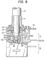
- the pull-push switch V of the type described above with reference to Figs. 4 to 7 can be combined or ganged with another pull-push switch generally indicated by the reference numeral VI as shown in Fig. 8.
- the elastic movable contact member 22 also serves as the locking means as described previously so that the auxiliary spring 10 used in the prior art ganged switch (See Fig. 3) can be eliminated. It only suffices to connect the lower end of the operating shaft 27 of the switch V to the upper end of the operating shaft of the pull-push switch VI.
- the pull-push switch VI does not constitute the present invention so that no detailed description thereof shall be made in this specification. For instance, it may be of the type described with reference to Fig. 3. That is, it is closed or opened as the operating shaft 27 of the pull-push switch V is pushed or pulled.
- Fig. 9 is shown a modification of the embodiment of Fig. 5.
- One leg 24a of the elastic movable contact member 22 is extended out of the casing 33 and used as the stationary contact or terminal 26 of the switch V shown in Figs. 4 to 7. Therefore, the pull-push switch can be made simple in construction and subsequently fabrication.
- the pull-push switches of the type described above are most frequently combined with rotary type variable resistors.
- the operating shaft 27 is rotated to rotate the wiper or the like of the variable resistor, small vibration or impact tends to be exerted to the shaft 27 in the axial direction thereof and consequently the shaft 27 is caused to move axially.
- the operating shaft 27 is forced to move upwardly from the closed position (See Fig. 6A)
- the legs 23 and 24 ride over the conically tapered portion 28a so that they are moved away from each other and hence from the stationary contacts or terminals 25 and 26.
- the pull-push switch V is erratically opened.
- the embodiment of the present invention was made to overcome this problem.
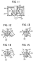
- the switch is opened when the operating shaft 27 is pushed in, but when the shaft 27 is pulled out the switch Va is closed. That is, the action of this embodiment is reversal of that of the first embodiment. Therefore, the cam 31 is inverted in the second embodiment. More specifically, the upper cylindrical portion 30 is greater in diameter than the lower cylindrical portion 29.
- one of the legs 23 and 24 is extended as shown in Fig. 9 and used as one of the stationary contacts or terminals 25 and 26 though not specifically shown in Fig. 10 or 11.
- a stationary contact 35 is interposed between the legs 23 and 24.
- the inside walls of the casing 33 are lined with insulating covers 36.
- Reference numeral 34 designates an end plate and 37 designates a resistor of the rotary type variable resistor VII.
- the legs 23 and 24 of the elastic movable contact member 22 are staggered in the vertical or axial direction. More specifically, the edge of the leg 23 is vertically or axially spaced apart by a distance I from the edge of the leg 24.
- the leg 23 With the operating shaft 27 in the pulled position, the leg 23 is made into contact with the small-diameter portion 29 of the cam 31 as shown in Fig. 10 while the ridge of the leg 24 is made into contact with the stationary contact 35 under a suitable pressure, whereby the switch Va is closed.
- the distance of vertical or axial misalignment between the edges of the legs 23 and 24 is so determined as to satisfy the following conditions.
- the switch closed or the operating shaft 27 in the pulled position only the leg 23 must be maintained in contact with the small-diameter portion 29 of the cam 31.
- the switch in the opened state that is, the operating shaft 27 in the pushed position
- the leg 24 With the switch in the opened state; that is, the operating shaft 27 in the pushed position, the leg 24 must be maintained in contact with the large-diameter portion 30 of the cam 31 so that both the legs 23 and 24 must be spaced apart from the stationary contact 35.
- FIG. 16 is shown the embodiment of the present invention in which a pull-push switch of the present invention is combined with a rotary switch VIII.
- Reference numeral 38 designates a switching cam securely fitted over the operating shaft 27 for rotation in unison therewith; 39, a movable contact rotatably supported by a rivet or the like 41 on a base 40 for engagement with or disengagement from a stationary contact 42; 43, a spring loaded between the movable contact 39 and the base 40; and 44, a casing for the rotary switch VIII.
- the operating shaft can be positively maintained in its pulled or pushed position even when small vibration or impact is exerted to it.
Landscapes
- Adjustable Resistors (AREA)
Claims (5)
Applications Claiming Priority (4)
| Application Number | Priority Date | Filing Date | Title |
|---|---|---|---|
| JP156665/80 | 1980-10-31 | ||
| JP15666580U JPS5778526U (de) | 1980-10-31 | 1980-10-31 | |
| JP7357281U JPS638038Y2 (de) | 1981-05-20 | 1981-05-20 | |
| JP73572/81 | 1981-05-20 |
Publications (2)
| Publication Number | Publication Date |
|---|---|
| EP0051257A1 EP0051257A1 (de) | 1982-05-12 |
| EP0051257B1 true EP0051257B1 (de) | 1984-09-19 |
Family
ID=26414715
Family Applications (1)
| Application Number | Title | Priority Date | Filing Date |
|---|---|---|---|
| EP81109035A Expired EP0051257B1 (de) | 1980-10-31 | 1981-10-27 | Druck-Ziehschalter |
Country Status (3)
| Country | Link |
|---|---|
| US (1) | US4409448A (de) |
| EP (1) | EP0051257B1 (de) |
| DE (1) | DE3166200D1 (de) |
Families Citing this family (3)
| Publication number | Priority date | Publication date | Assignee | Title |
|---|---|---|---|---|
| US4525613A (en) * | 1984-01-20 | 1985-06-25 | Apple Computer, Inc. | Spiral spring keyboard switch with hairpin spring tactile feedback |
| ITTO20020008U1 (it) * | 2002-01-18 | 2003-07-18 | Urmet Domus Spa | ,,contattore a pulsante per l'attivazione di segnali di chiamata in pulsantiere,, |
| EP1435633B1 (de) * | 2002-12-31 | 2007-06-20 | ETA SA Manufacture Horlogère Suisse | Betätigungsvorrichtung mit mehreren axialen Stellungen für ein elektronisches Gerät |
Family Cites Families (10)
| Publication number | Priority date | Publication date | Assignee | Title |
|---|---|---|---|---|
| US2031067A (en) * | 1933-08-03 | 1936-02-18 | Borg Warner | Automatic transmission |
| US2453231A (en) * | 1945-08-09 | 1948-11-09 | Ibm | Electrical switch |
| US3219776A (en) * | 1950-12-05 | 1965-11-23 | Yerkovich Simon | Switch actuator mechanism |
| DE1123732B (de) * | 1960-01-07 | 1962-02-15 | Standard Elektrik Lorenz Ag | Drucktaste oder Drucktastenschalter, insbesondere fuer Fernmeldeanlagen, mit einem die Schaltfolge beeinflussenden Glied |
| US2999991A (en) * | 1960-06-20 | 1961-09-12 | Cts Corp | Grounding means for electrical controls with a reciprocating shaft |
| DE1177727B (de) * | 1960-07-11 | 1964-09-10 | Yale & Towne A G | Drehzahlsteller fuer Elektromotoren |
| US3236971A (en) * | 1963-02-28 | 1966-02-22 | Zenith Radio Corp | Combination on-off switch and circuit-breaker |
| US3274355A (en) * | 1965-02-08 | 1966-09-20 | Scantlin Electronics Inc | Cam operated snap switch having wire contacts |
| DE1580714B1 (de) * | 1966-05-13 | 1970-10-15 | Rau Swf Autozubehoer | Schalteinrichtung,insbesondere fuer Lenkstockschalter an Kraftfahrzeugen |
| DE2952107A1 (de) * | 1979-12-22 | 1981-06-25 | Cherry Mikroschalter Gmbh, 8572 Auerbach | Tastenschalter |
-
1981
- 1981-10-27 DE DE8181109035T patent/DE3166200D1/de not_active Expired
- 1981-10-27 EP EP81109035A patent/EP0051257B1/de not_active Expired
- 1981-10-29 US US06/316,283 patent/US4409448A/en not_active Expired - Lifetime
Also Published As
| Publication number | Publication date |
|---|---|
| EP0051257A1 (de) | 1982-05-12 |
| DE3166200D1 (en) | 1984-10-25 |
| US4409448A (en) | 1983-10-11 |
Similar Documents
| Publication | Publication Date | Title |
|---|---|---|
| US5178265A (en) | Push-push snap switch | |
| KR860003180Y1 (ko) | 재 크 | |
| US4215254A (en) | Pressure switch with resiliently mounted contact | |
| US2507381A (en) | Switch mechanism | |
| US4665286A (en) | Motor starting and automatic reversing switch | |
| US5929742A (en) | Trip-free, manual reset thermostat | |
| US4409448A (en) | Pull-push switch | |
| US5082997A (en) | Quick-break miniature switch | |
| US3496511A (en) | Thermostatic switch for small electrical appliances | |
| US4951017A (en) | Electromagnetic relay | |
| JP3274135B2 (ja) | 各真空バルブごとに極操作ユニットを備えた多極真空遮断器 | |
| US2941047A (en) | Electric switch | |
| US4843195A (en) | Switch having dust-proof cover | |
| US4492833A (en) | Door jamb switch | |
| US4280027A (en) | Switch blade mechanism and multi-arrangement | |
| US4321771A (en) | Vehicle window glass guiding apparatus | |
| US4459444A (en) | Condition responsive switch | |
| US4602137A (en) | Pull-push switch | |
| US2529970A (en) | Electric switch | |
| US4814558A (en) | Contact mechanism for a switch | |
| US4562318A (en) | Momentary switch | |
| JPH07153347A (ja) | マイクロスイッチ | |
| US1882857A (en) | Electric switch | |
| US4163132A (en) | Double-pole single-throw switch | |
| US3212351A (en) | Thermostatic switch and method of assembly |
Legal Events
| Date | Code | Title | Description |
|---|---|---|---|
| PUAI | Public reference made under article 153(3) epc to a published international application that has entered the european phase |
Free format text: ORIGINAL CODE: 0009012 |
|
| 17P | Request for examination filed |
Effective date: 19811027 |
|
| AK | Designated contracting states |
Designated state(s): DE FR GB |
|
| GRAA | (expected) grant |
Free format text: ORIGINAL CODE: 0009210 |
|
| AK | Designated contracting states |
Designated state(s): DE FR GB |
|
| REF | Corresponds to: |
Ref document number: 3166200 Country of ref document: DE Date of ref document: 19841025 |
|
| ET | Fr: translation filed | ||
| PLBE | No opposition filed within time limit |
Free format text: ORIGINAL CODE: 0009261 |
|
| STAA | Information on the status of an ep patent application or granted ep patent |
Free format text: STATUS: NO OPPOSITION FILED WITHIN TIME LIMIT |
|
| 26N | No opposition filed | ||
| REG | Reference to a national code |
Ref country code: GB Ref legal event code: 746 Effective date: 19950928 |
|
| REG | Reference to a national code |
Ref country code: FR Ref legal event code: D6 |
|
| PGFP | Annual fee paid to national office [announced via postgrant information from national office to epo] |
Ref country code: FR Payment date: 19981009 Year of fee payment: 18 |
|
| PGFP | Annual fee paid to national office [announced via postgrant information from national office to epo] |
Ref country code: GB Payment date: 19981030 Year of fee payment: 18 |
|
| PGFP | Annual fee paid to national office [announced via postgrant information from national office to epo] |
Ref country code: DE Payment date: 19981103 Year of fee payment: 18 |
|
| PG25 | Lapsed in a contracting state [announced via postgrant information from national office to epo] |
Ref country code: GB Free format text: LAPSE BECAUSE OF NON-PAYMENT OF DUE FEES Effective date: 19991027 |
|
| GBPC | Gb: european patent ceased through non-payment of renewal fee |
Effective date: 19991027 |
|
| PG25 | Lapsed in a contracting state [announced via postgrant information from national office to epo] |
Ref country code: FR Free format text: LAPSE BECAUSE OF NON-PAYMENT OF DUE FEES Effective date: 20000630 |
|
| PG25 | Lapsed in a contracting state [announced via postgrant information from national office to epo] |
Ref country code: DE Free format text: LAPSE BECAUSE OF NON-PAYMENT OF DUE FEES Effective date: 20000801 |
|
| REG | Reference to a national code |
Ref country code: FR Ref legal event code: ST |