EP0051263A2 - Porte-outil à échange rapide pour tours - Google Patents
Porte-outil à échange rapide pour tours Download PDFInfo
- Publication number
- EP0051263A2 EP0051263A2 EP81109083A EP81109083A EP0051263A2 EP 0051263 A2 EP0051263 A2 EP 0051263A2 EP 81109083 A EP81109083 A EP 81109083A EP 81109083 A EP81109083 A EP 81109083A EP 0051263 A2 EP0051263 A2 EP 0051263A2
- Authority
- EP
- European Patent Office
- Prior art keywords
- holder
- quick
- clamping
- guide
- eccentric bolt
- Prior art date
- Legal status (The legal status is an assumption and is not a legal conclusion. Google has not performed a legal analysis and makes no representation as to the accuracy of the status listed.)
- Granted
Links
Images

Classifications
-
- B—PERFORMING OPERATIONS; TRANSPORTING
- B23—MACHINE TOOLS; METAL-WORKING NOT OTHERWISE PROVIDED FOR
- B23B—TURNING; BORING
- B23B29/00—Holders for non-rotary cutting tools; Boring bars or boring heads; Accessories for tool holders
- B23B29/04—Tool holders for a single cutting tool
-
- Y—GENERAL TAGGING OF NEW TECHNOLOGICAL DEVELOPMENTS; GENERAL TAGGING OF CROSS-SECTIONAL TECHNOLOGIES SPANNING OVER SEVERAL SECTIONS OF THE IPC; TECHNICAL SUBJECTS COVERED BY FORMER USPC CROSS-REFERENCE ART COLLECTIONS [XRACs] AND DIGESTS
- Y10—TECHNICAL SUBJECTS COVERED BY FORMER USPC
- Y10T—TECHNICAL SUBJECTS COVERED BY FORMER US CLASSIFICATION
- Y10T82/00—Turning
- Y10T82/25—Lathe
- Y10T82/2572—Attachment
- Y10T82/2574—Stop [e.g., carriage, tool, work, etc.]
-
- Y—GENERAL TAGGING OF NEW TECHNOLOGICAL DEVELOPMENTS; GENERAL TAGGING OF CROSS-SECTIONAL TECHNOLOGIES SPANNING OVER SEVERAL SECTIONS OF THE IPC; TECHNICAL SUBJECTS COVERED BY FORMER USPC CROSS-REFERENCE ART COLLECTIONS [XRACs] AND DIGESTS
- Y10—TECHNICAL SUBJECTS COVERED BY FORMER USPC
- Y10T—TECHNICAL SUBJECTS COVERED BY FORMER US CLASSIFICATION
- Y10T82/00—Turning
- Y10T82/25—Lathe
- Y10T82/2585—Tool rest
Definitions
- the innovation relates to a quick-change tool holder for lathes, consisting of a basic holder and a tool holder for the tool holder, which can be positioned relative to each other on prismatic or round guides by abutment against an adjustable stop and can be clamped perpendicular to the guide level by means of a clamping device Actuators for the clamping device are arranged in the change holder.
- Such a tool holder is known from DE-OS 27 45 4o2, in which only one adjustment direction or two adjustment directions are provided depending on the type of application for a plunging tool (FIGS. 1-3) or a facing tool (FIGS. 4-6), in the latter case, the necessary adjustment and clamping means are identical, that is, they are also duplicated.
- tools for multi-spindle automatic lathes are not double-adjustable and only one adjustment level is provided, which is arranged in such a way that the turning height can be adjusted with a stop screw (track, MULTI-SPINDLE LATHE-AUTOMATES, Carl Hanser Verlag, Kunststoff, Page 173).
- This generally customary arrangement of the guide level has the disadvantage that an adjustment of the workpiece dimensions is not possible.
- opposing threads are formed in axially separated areas, which engage in clamping jaws which are guided in a non-rotatable manner in the interchangeable holder and which accordingly move towards one another when the screw is actuated. or moved away from each other.
- Wedge surfaces are formed on the clamping sides of these clamping jaws, which grip appropriately designed wedge surfaces of a sliding block arranged displaceably in a T-slot of the basic holder and are thereby able to clamp the interchangeable insert with respect to the basic holder.
- clamping screw is arranged transversely to the longitudinal axis of the holder in an interchangeable insert. If several interchangeable inserts have to be arranged close to each other on a plate-shaped basic holder, then access to the clamping device of most interchangeable inserts is blocked and the neighboring interchangeable inserts must first be removed before the clamping of an inner insert can be released.
- Both Ausqestaltungsformen the clamping device in DE-OS 27 45 4o7 also have the disadvantage that when the interchangeable insert is placed on the basic holder, the exact engagement between the clamping element and the sliding block cannot be monitored visually and cannot be produced by a long training of the sliding block, because a long sliding block requires a correspondingly long shifting of the change holder before lifting.
- the innovation is based on the object in a quick-change tool holder of the type mentioned with only one guide level, in which one or more prismatic or round guide means are provided, to arrange them so that a sufficient adjustability of the tool is made possible for all types of use.
- the clamping device should be improved so that the after Parts of the known tool holder can be avoided and with only a short actuation path, immediate loosening can take place both in the direction of the guide means and perpendicular to the guide plane.
- this object is achieved in that the guide means are arranged parallel to the clamping surface of the basic holder on the tool slide and at right angles to the main feed direction, in that the clamping device has an eccentric bolt which projects through a bore in a clamping piece, and in that the eccentric bolt is both rotatable in the interchangeable insert as well as axially displaceable in the main feed direction and is displaceable from an operative position to an ineffective position in which it releases the clamping piece which is displaceable in the basic holder in a T-slot by means of a sliding block, so that the interchangeable holder can be removed perpendicular to the guide plane.
- a quick-change tool holding system for a lathe requires three adjustment directions per se, namely the x-direction for the diameter adjustment, the y-direction for the height adjustment (turning height) and the z-direction for the length adjustment. If all three adjustment devices are arranged in the tool holder, which is technically possible - solutions with four-fold adjustment have already become known, including a swiveling movement - the costs are so high that the use of these tool holders is only economically justifiable in exceptional cases . In any case, these solutions are uneconomical for a quick-change tool holding system, which must be offered as normal accessories for a lathe.
- the innovation is therefore based on the consideration that it makes more sense to move one of these adjustment options into the lathe itself, namely the positioning of the basic holder in the feed direction, for example using path-limiting stops for the feed slide, and the formation of a slide bar upper part or the arrangement of adjustable stops for the basic holder on the slide. It follows from this that then only one adjustment option transverse to the feed direction is sufficient in the tool holder to nevertheless ensure adjustment in two directions (x and z direction). The resulting economic advantage of making use of the adjustment facility arranged in the machine for all tool holders is evident.
- the quick-change tool holder according to the invention can be used not only with mechanically or hydraulically operated lathes, in particular multi-spindle automatic lathes, but because of its economic advantages, e.g. can also be used with numerically controlled lathes. This provides a general applicability that further underlines the economic importance.
- a first advantageous embodiment results from the fact that the T-slot with the sliding block of the clamping piece is arranged asymmetrically between the two guides so that it is closer to the Tool cutting edge runs adjacent to the other guide.
- This configuration makes it possible, when using only one such clamping device, to safely absorb the tilting moments resulting from the attack of the turning tool on the workpiece and to transmit them to the basic holder.
- the eccentric pin is so spring-loaded in the axial direction that it is automatically displaced in the axial direction after the eccentric tension has been released. As a result, the state of the clamping device is displayed visibly from the outside.
- a special embodiment of the new clamping device results from the fact that the eccentric bolt has an axial groove and a radial groove adjoining one end thereof, into which a guide means arranged in the form of a screw or a pin engages. This prevents the eccentric bolt from being lost.
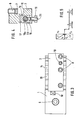
- the drawing shows a basic holder 1 with two circular guides 2 and an exchangeable insert 3 attachable thereon.
- the basic holder 1 is designed as a plate and has an attachment 4 with which it is inserted into a groove in a slide of a lathe and fastened by means of screws 5 and sliding blocks 6 can be.
- the tool (not shown), namely a lathe tool, is clamped in the insert 3 via a pressure plate 7 by means of clamping screws 8 in a known manner.
- the pressure plate 7 is held in the interchangeable insert 3 by a screw 1o loaded by a spring 9 so that it is constantly on the Clamping screws 8 abut and thus allow unhindered replacement of the tool.
- the position of the tool in the tool channel 11 can be adjusted using adjusting screws 12 and 13 (13a, 13b).
- a sliding block 15 is slidably inserted, which engages with a cylindrical extension 16 in a bore 17 of the interchangeable insert 3 and forms a standing piece.
- G parallel to the tool press channel 11 is alternately insert 3 an eccentric pin 18 mounted, the 19 interspersed with its eccentric portion 18a is a hole in the extension 16 of the sliding block 15 and is supported with a smaller diameter cylindrical end portion 18b in the change insert.
- a compression spring 2o which is fastened on its other end face 2oa in a suitable manner, for example by gluing, in the bore 21 receiving the end part 18b of the eccentric pin 18.
- the eccentric pin 18 contains a circumferential groove 22 and an axial groove 23 which opens at one end into the circumferential groove 22, extends through the eccentric part 18a and is closed on the end face before the end there.
- a screw 24 arranged in the interchangeable insert engages in the circumferential groove 22, so that the eccentric bolt 18 can only be rotated in this position, but cannot be axially displaced.
- the interchangeable insert 3 is clamped with the basic holder 1 or the clamp is released.
- the eccentric pin 18 If the eccentric pin 18 is rotated when loosening so that the screw 24 comes in front of the axial groove 23, then the eccentric pin 18 is automatically moved under the action of the spring 2o into a more protruding position from the interchangeable insert.
- the eccentric bolt 18 thus always assumes an externally recognizable position in the released state, which signals the installer to the release position.
- the groove 23 is formed so long that the extension 16 of the sliding block is released when the eccentric pin 18 is pulled out to the extreme position. In this position, the interchangeable insert 3 can be lifted off the basic holder 1 perpendicular to the circular guides 2. So that the sliding block 15 is not lost, a spring-loaded clamping bolt 25 is arranged in a known manner in its base, which secures the sliding block in the T-slot 14 in a frictionally locking manner.
- a further, preferably dovetail-shaped groove 26 is formed in the basic holder 1 transversely to the feed direction, in which a stop 27 is clamped by means of a threaded pin 28.
- the interchangeable insert 3 can be adjusted against this stop 27 by means of an adjusting screw 29.
- FIG. 5 shows the load conditions under the action of the cutting forces F, which is broken down into the components Fx and Fy.
- the forces involved in overhead machining are shown in dashed lines and indicated by an apostrophe.
Landscapes
- Engineering & Computer Science (AREA)
- Mechanical Engineering (AREA)
- Cutting Tools, Boring Holders, And Turrets (AREA)
- Gyroscopes (AREA)
- Turning (AREA)
- Drilling Tools (AREA)
- Gripping On Spindles (AREA)
Priority Applications (1)
| Application Number | Priority Date | Filing Date | Title |
|---|---|---|---|
| AT81109083T ATE17453T1 (de) | 1980-11-03 | 1981-10-28 | Schnellwechsel-werkzeughalter fuer drehmaschinen. |
Applications Claiming Priority (2)
| Application Number | Priority Date | Filing Date | Title |
|---|---|---|---|
| DE19808029160U DE8029160U1 (de) | 1980-11-03 | 1980-11-03 | Schnellwechsel-werkzeughalter fuer drehmaschinen |
| DE8029160U | 1980-11-03 |
Publications (3)
| Publication Number | Publication Date |
|---|---|
| EP0051263A2 true EP0051263A2 (fr) | 1982-05-12 |
| EP0051263A3 EP0051263A3 (en) | 1983-07-20 |
| EP0051263B1 EP0051263B1 (fr) | 1986-01-15 |
Family
ID=6720235
Family Applications (1)
| Application Number | Title | Priority Date | Filing Date |
|---|---|---|---|
| EP81109083A Expired EP0051263B1 (fr) | 1980-11-03 | 1981-10-28 | Porte-outil à échange rapide pour tours |
Country Status (5)
| Country | Link |
|---|---|
| US (1) | US4515049A (fr) |
| EP (1) | EP0051263B1 (fr) |
| AT (1) | ATE17453T1 (fr) |
| BR (1) | BR8106925A (fr) |
| DE (2) | DE8029160U1 (fr) |
Cited By (2)
| Publication number | Priority date | Publication date | Assignee | Title |
|---|---|---|---|---|
| EP0485662A1 (fr) * | 1990-11-16 | 1992-05-20 | GÖLTENBODT PRÄZISIONSWERKZEUG- UND MASCHINENFABRIK GmbH & CO. | Méthode et dispositif de change avec de préréglage pour machines travaillant par enlèvement de copeaux |
| CN103286602A (zh) * | 2013-05-14 | 2013-09-11 | 六安市龙兴汽车零部件有限公司 | 汽车变速器后盖多用偏心车夹具 |
Families Citing this family (10)
| Publication number | Priority date | Publication date | Assignee | Title |
|---|---|---|---|---|
| US5367754A (en) * | 1991-03-29 | 1994-11-29 | Hardinge Brothers, Inc. | Gang tooling for a computerized numerically controlled lathe |
| DE10224126B4 (de) * | 2002-05-29 | 2004-05-13 | Ernst Graf | Mehrfachwerkzeughalter für eine Drehmaschine, insbesondere für einen Langdrehautomaten |
| DE102005029140B4 (de) * | 2005-06-23 | 2008-04-03 | Elke Weigelt | Werkzeugbefestigungseinrichtung für einen Keiltrieb |
| DE102005052314A1 (de) * | 2005-11-01 | 2007-05-03 | Satisloh Gmbh | Fast-Tool-Anordnung, insbesondere für Drehmaschinen zur Bearbeitung von optischen Werkstücken |
| DE102006036654B4 (de) * | 2006-08-03 | 2008-12-04 | Harald Weigelt | Keiltrieb mit Zwangsrückholeinrichtung |
| US8430385B2 (en) * | 2007-09-24 | 2013-04-30 | Harald Weigelt | Wedge drive with slider receiving means |
| CN101524765B (zh) * | 2009-04-13 | 2010-07-21 | 吴淼东 | 小内孔车槽刀 |
| JP5539012B2 (ja) * | 2010-05-17 | 2014-07-02 | 東芝機械株式会社 | 精密ロール旋盤の自動工具交換装置 |
| CN112548122B (zh) * | 2020-12-07 | 2022-04-22 | 台州市路桥先创自动化设备有限公司 | 一种便于装刀的车床用加工装置 |
| CN112775669B (zh) * | 2021-02-03 | 2024-08-30 | 常州迈纳光电科技有限公司 | 一种超精密车铣复合数控机床 |
Family Cites Families (12)
| Publication number | Priority date | Publication date | Assignee | Title |
|---|---|---|---|---|
| US3107562A (en) * | 1963-10-22 | Tool head with removable tool holder | ||
| US2023869A (en) * | 1933-11-22 | 1935-12-10 | Sundstrand Machine Tool Co | Work supports for machine tools |
| US2763176A (en) * | 1953-07-09 | 1956-09-18 | Maurice J Chartier | Cross slide tool holder |
| US3163062A (en) * | 1962-07-25 | 1964-12-29 | Honeywell Inc | Tool holders |
| US3232153A (en) * | 1964-05-28 | 1966-02-01 | Gen Motors Corp | Adjustable tool block |
| US3503287A (en) * | 1967-03-17 | 1970-03-31 | Robert C Zeller | Tool and toolholder |
| US3545319A (en) * | 1969-02-03 | 1970-12-08 | Usm Corp | Tool block |
| DE1939132A1 (de) * | 1969-08-01 | 1971-02-04 | Schiess Ag | Schnellwechsel-Werkzeughalter |
| US3822619A (en) * | 1969-08-29 | 1974-07-09 | Willen & Cie C | Tool holder assembly having means for selectively adjusting the position of the work tool |
| DE2150518A1 (de) * | 1971-10-09 | 1973-05-17 | Walter Goeltenbodt Kg | Schnellwechsel- und voreinstellbarer drehmeisselhalter fuer rund- und flachformmeissel |
| US4043229A (en) * | 1976-04-05 | 1977-08-23 | Devlieg Machine Company | Self-retracting tool |
| CH612869A5 (fr) * | 1977-08-15 | 1979-08-31 | Emile Albert Minder |
-
1980
- 1980-11-03 DE DE19808029160U patent/DE8029160U1/de not_active Expired
-
1981
- 1981-10-23 US US06/314,228 patent/US4515049A/en not_active Expired - Fee Related
- 1981-10-27 BR BR8106925A patent/BR8106925A/pt not_active IP Right Cessation
- 1981-10-28 EP EP81109083A patent/EP0051263B1/fr not_active Expired
- 1981-10-28 DE DE8181109083T patent/DE3173525D1/de not_active Expired
- 1981-10-28 AT AT81109083T patent/ATE17453T1/de not_active IP Right Cessation
Cited By (2)
| Publication number | Priority date | Publication date | Assignee | Title |
|---|---|---|---|---|
| EP0485662A1 (fr) * | 1990-11-16 | 1992-05-20 | GÖLTENBODT PRÄZISIONSWERKZEUG- UND MASCHINENFABRIK GmbH & CO. | Méthode et dispositif de change avec de préréglage pour machines travaillant par enlèvement de copeaux |
| CN103286602A (zh) * | 2013-05-14 | 2013-09-11 | 六安市龙兴汽车零部件有限公司 | 汽车变速器后盖多用偏心车夹具 |
Also Published As
| Publication number | Publication date |
|---|---|
| ATE17453T1 (de) | 1986-02-15 |
| EP0051263B1 (fr) | 1986-01-15 |
| BR8106925A (pt) | 1982-07-13 |
| US4515049A (en) | 1985-05-07 |
| EP0051263A3 (en) | 1983-07-20 |
| DE3173525D1 (en) | 1986-02-27 |
| DE8029160U1 (de) | 1981-04-16 |
Similar Documents
| Publication | Publication Date | Title |
|---|---|---|
| DE2339873C2 (de) | Anordnung zum Einstellen und Befestigen eines ein Schneidplättchen tragenden Blocks in einer nutförmigen Aufnahme im Werkzeugkörper eines spanabhebenden Werkzeugs | |
| EP0117557A1 (fr) | Palette porte-pièces sur des machines-outils | |
| EP0051263B1 (fr) | Porte-outil à échange rapide pour tours | |
| WO2017198759A1 (fr) | Support pour un outil d'usinage par enlèvement de copeaux, en particulier pour un outil de tournage longitudinal | |
| DE19643590A1 (de) | Ausdrehwerkzeug | |
| DE19845386A1 (de) | Stempel für eine Maschine zum Bearbeiten von Werkstücken | |
| EP0180866B1 (fr) | Dispositif de fixation d'un objet | |
| DE3528943C1 (de) | Aufsatzbacke fuer Spannfutter | |
| DE1936471C3 (de) | Werkzeughalter | |
| DE4207353A1 (de) | Werkzeughalter fuer ein schneidwerkzeug | |
| DE102019112337A1 (de) | Werkzeugaufnahmevorrichtung | |
| EP0421069B1 (fr) | Dispositif d'alignement | |
| DE10137887A1 (de) | Spannvorrichtung | |
| DE2100860A1 (de) | Werkzeugaufnehmer an Werkzeugmaschinen | |
| DE2745402C2 (de) | Werkzeughalter für eine Werkzeugmaschine | |
| DE3012705C2 (fr) | ||
| DE2700726C2 (de) | Drehmaschine | |
| DE19739269C1 (de) | Spannvorrichtung, insbesondere Maschinenschraubstock | |
| DE3916582C2 (fr) | ||
| DE1922499C (de) | Backenfutter mit auswechselbare Auf satzbacken tragenden Grundbacken | |
| DE2622566B2 (de) | Rohrabschneider zum Ablängen und gleichzeitigen Anschrägen von Rohren, insbesondere Kunststoffrohren | |
| EP0588997A1 (fr) | Dispositif de blocage multiple | |
| DE29810720U1 (de) | Spannbackenhalterung | |
| DE3632389C2 (fr) | ||
| DE3929005A1 (de) | Halterung fuer ein maschinenwerkzeug |
Legal Events
| Date | Code | Title | Description |
|---|---|---|---|
| PUAI | Public reference made under article 153(3) epc to a published international application that has entered the european phase |
Free format text: ORIGINAL CODE: 0009012 |
|
| AK | Designated contracting states |
Designated state(s): AT CH DE FR GB IT SE |
|
| PUAL | Search report despatched |
Free format text: ORIGINAL CODE: 0009013 |
|
| AK | Designated contracting states |
Designated state(s): AT CH DE FR GB IT LI SE |
|
| 17P | Request for examination filed |
Effective date: 19830729 |
|
| ITF | It: translation for a ep patent filed | ||
| GRAA | (expected) grant |
Free format text: ORIGINAL CODE: 0009210 |
|
| AK | Designated contracting states |
Designated state(s): AT CH DE FR GB IT LI SE |
|
| REF | Corresponds to: |
Ref document number: 17453 Country of ref document: AT Date of ref document: 19860215 Kind code of ref document: T |
|
| REF | Corresponds to: |
Ref document number: 3173525 Country of ref document: DE Date of ref document: 19860227 |
|
| ET | Fr: translation filed | ||
| PGFP | Annual fee paid to national office [announced via postgrant information from national office to epo] |
Ref country code: AT Payment date: 19861015 Year of fee payment: 6 |
|
| PLBE | No opposition filed within time limit |
Free format text: ORIGINAL CODE: 0009261 |
|
| STAA | Information on the status of an ep patent application or granted ep patent |
Free format text: STATUS: NO OPPOSITION FILED WITHIN TIME LIMIT |
|
| 26N | No opposition filed | ||
| PG25 | Lapsed in a contracting state [announced via postgrant information from national office to epo] |
Ref country code: AT Effective date: 19871028 |
|
| PG25 | Lapsed in a contracting state [announced via postgrant information from national office to epo] |
Ref country code: SE Effective date: 19871029 |
|
| PG25 | Lapsed in a contracting state [announced via postgrant information from national office to epo] |
Ref country code: LI Effective date: 19871031 Ref country code: CH Effective date: 19871031 |
|
| GBPC | Gb: european patent ceased through non-payment of renewal fee | ||
| PG25 | Lapsed in a contracting state [announced via postgrant information from national office to epo] |
Ref country code: FR Free format text: LAPSE BECAUSE OF NON-PAYMENT OF DUE FEES Effective date: 19880630 |
|
| REG | Reference to a national code |
Ref country code: CH Ref legal event code: PL |
|
| REG | Reference to a national code |
Ref country code: FR Ref legal event code: ST |
|
| PG25 | Lapsed in a contracting state [announced via postgrant information from national office to epo] |
Ref country code: GB Effective date: 19881118 |
|
| EUG | Se: european patent has lapsed |
Ref document number: 81109083.6 Effective date: 19880707 |
|
| PGFP | Annual fee paid to national office [announced via postgrant information from national office to epo] |
Ref country code: DE Payment date: 19951223 Year of fee payment: 15 |
|
| PG25 | Lapsed in a contracting state [announced via postgrant information from national office to epo] |
Ref country code: DE Effective date: 19970701 |