EP0051299B1 - Circuit de contrôle et son application dans des véhicules - Google Patents
Circuit de contrôle et son application dans des véhicules Download PDFInfo
- Publication number
- EP0051299B1 EP0051299B1 EP81109330A EP81109330A EP0051299B1 EP 0051299 B1 EP0051299 B1 EP 0051299B1 EP 81109330 A EP81109330 A EP 81109330A EP 81109330 A EP81109330 A EP 81109330A EP 0051299 B1 EP0051299 B1 EP 0051299B1
- Authority
- EP
- European Patent Office
- Prior art keywords
- switched
- control circuit
- switch
- load
- way
- Prior art date
- Legal status (The legal status is an assumption and is not a legal conclusion. Google has not performed a legal analysis and makes no representation as to the accuracy of the status listed.)
- Expired
Links
- 235000014676 Phragmites communis Nutrition 0.000 description 10
- 238000011156 evaluation Methods 0.000 description 7
- 230000002950 deficient Effects 0.000 description 3
- 238000012544 monitoring process Methods 0.000 description 2
- 230000001681 protective effect Effects 0.000 description 1
- 210000002023 somite Anatomy 0.000 description 1
Images
Classifications
-
- B—PERFORMING OPERATIONS; TRANSPORTING
- B60—VEHICLES IN GENERAL
- B60Q—ARRANGEMENT OF SIGNALLING OR LIGHTING DEVICES, THE MOUNTING OR SUPPORTING THEREOF OR CIRCUITS THEREFOR, FOR VEHICLES IN GENERAL
- B60Q11/00—Arrangement of monitoring devices for devices provided for in groups B60Q1/00 - B60Q9/00
- B60Q11/005—Arrangement of monitoring devices for devices provided for in groups B60Q1/00 - B60Q9/00 for lighting devices, e.g. indicating if lamps are burning or not
-
- G—PHYSICS
- G01—MEASURING; TESTING
- G01R—MEASURING ELECTRIC VARIABLES; MEASURING MAGNETIC VARIABLES
- G01R19/00—Arrangements for measuring currents or voltages or for indicating presence or sign thereof
- G01R19/165—Indicating that current or voltage is either above or below a predetermined value or within or outside a predetermined range of values
- G01R19/16504—Indicating that current or voltage is either above or below a predetermined value or within or outside a predetermined range of values characterised by the components employed
- G01R19/16509—Indicating that current or voltage is either above or below a predetermined value or within or outside a predetermined range of values characterised by the components employed using electromagnetic relays, e.g. reed relay
Definitions
- the invention relates to a test circuit for detecting interruptions in electrical consumer circuits, in which a display device can be switched in the event of an interruption in the consumer circuit, and its use in motor vehicles.
- Test circuits are already known in which a resistor (series resistor) is connected in the consumer circuit.
- the voltage drop across these resistors serves as a measure of the control of the consumer circuit, cf. published German patent application DE-A-2 147 681.
- a voltage drop is generally undesirable. If it is kept low through the selection of small resistance values, this requires a greater circuit outlay for the evaluation.
- the consumer circuit can only be checked when it is switched on; this is referred to as a so-called warm query. If the device is not switched on, a fault cannot be detected in the consumer circuit to be monitored.
- the invention has for its object to provide a circuit arrangement which monitors a consumer circuit both in the switched off and in the switched on state, i. H. Displays faults automatically and regardless of the current operating state of the consumer circuit.
- a test circuit for detecting interruptions in electrical consumer circuits, in which a display device can be switched in the event of an interruption in the consumer circuit, in that an evaluation and display stage connected to the supply voltage has a connection point when it is connected to ground Display device is switched, and that from this connection point via a test stage lead two alternative connections to ground, the first connection being made via a switch which is actuated by the consumer current in such a way that it is only closed when the consumer circuit is switched on and is correct, and the second Connection takes place via a component which, when the consumer circuit is switched off, connects the connection point to ground via the components of the consumer circuit located after the consumer switch.
- the component producing the second connection can be a diode which is connected in the forward direction from the connection point to the consumer circuit.
- a protective tube switch inductively actuated by the consumer current is preferably used as the switch.
- the component producing the second connection can be a normally closed contact (changeover contact) integrated in the switch.
- the evaluation and display stage can comprise a light-emitting diode connected by a transistor. When using a changeover contact, the evaluation and display stage can also be simplified. It is particularly advantageous to use the test circuit to detect faults in lamp circuits in motor vehicles.
- the invention enables a circuit to be checked at any time, ie regardless of whether it is switched on or off.
- detecting errors in LAM p enstrom Vietnameseen in motor vehicles can be used both at start - z. B. when switching on the ignition - as well as while driving - z. B. after switching on the vehicle lights - the functionality of the lamps without gaps, ie at any time, and automatically, ie without the driver's intervention, monitored and displayed.
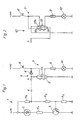
- the test circuit comprises an evaluation and display stage 1, which is connected on the one hand to the terminal +15 of a motor vehicle, ie, for example, at the ignition voltage of approx. 13 volts, and on the other hand to ground, ie, for example with a minus.
- R 1 to R 4 denote suitable resistors.
- Resistor R i serves as a series resistor for current limitation, the resistors R 2 to R 4 form a voltage divider, at which the base voltage for a switching transistor 3 is tapped between the resistors R 3 and R 4 . Between the resistors R 2 and R 3 is the entry point E to which the starting point A of the test station 4 is connected.
- the test stage 4 (Fig. 1) comprises a reed contact 5, which leads to ground, and a diode 6, which is connected in the forward direction from the connection point A to the consumer circuit 7, immediately after the consumer switch 8.
- the consumer circuit 7 is on the one hand to terminal +30, d. H. to the battery voltage of approximately + 13 volts, and on the other hand to ground, i.e. H. here connected to minus.
- the consumer switch 8 is followed by a coil 5a for actuating the reed contact 5, a fuse 9 for the consumer and, as a consumer, an incandescent lamp 10.
- This consumer circuit 7 represents a consumer circuit in a simplified form.
- FIG. 2 A variant 40 of test stage 4 is shown in FIG. 2.
- a reed switch 50 with normally closed contact 50a to the consumer circuit. 7 and arranged with a changeover contact 50b to ground.
- the normally closed contact 50a was provided instead of a diode (see FIG. 1).
- FIG. 2 shows the same consumer circuit as in FIG. 1, but a variant of the test stage, which is designated 40 here.
- the display device should now be switched on or off and how the display, optically or acoustically, should take place.
- the invention can also be constructed in terms of circuitry within the scope of the skilled person in such a way that minus at terminals 15 or 30 and There is a plus in mass, as is the case in practice for vehicle wiring in various countries.
Landscapes
- Physics & Mathematics (AREA)
- Engineering & Computer Science (AREA)
- Mechanical Engineering (AREA)
- Electromagnetism (AREA)
- General Physics & Mathematics (AREA)
- Testing Of Short-Circuits, Discontinuities, Leakage, Or Incorrect Line Connections (AREA)
- Electric Propulsion And Braking For Vehicles (AREA)
- Lighting Device Outwards From Vehicle And Optical Signal (AREA)
- Circuit Arrangement For Electric Light Sources In General (AREA)
Claims (6)
Applications Claiming Priority (2)
| Application Number | Priority Date | Filing Date | Title |
|---|---|---|---|
| DE3041206A DE3041206C2 (de) | 1980-11-03 | 1980-11-03 | Prüfschaltung zum Feststellen und Anzeigen von Unterbrechungen in elektrischen Verbraucherstromkreisen |
| DE3041206 | 1980-11-03 |
Publications (2)
| Publication Number | Publication Date |
|---|---|
| EP0051299A1 EP0051299A1 (fr) | 1982-05-12 |
| EP0051299B1 true EP0051299B1 (fr) | 1984-06-06 |
Family
ID=6115728
Family Applications (1)
| Application Number | Title | Priority Date | Filing Date |
|---|---|---|---|
| EP81109330A Expired EP0051299B1 (fr) | 1980-11-03 | 1981-10-30 | Circuit de contrôle et son application dans des véhicules |
Country Status (3)
| Country | Link |
|---|---|
| US (1) | US4447806A (fr) |
| EP (1) | EP0051299B1 (fr) |
| DE (1) | DE3041206C2 (fr) |
Families Citing this family (19)
| Publication number | Priority date | Publication date | Assignee | Title |
|---|---|---|---|---|
| DE3141569A1 (de) * | 1981-10-20 | 1983-05-05 | Bosch-Siemens Hausgeräte GmbH, 7000 Stuttgart | Spaltpolmotor zum starren antrieb eines mechanisch blockierbaren geraetes |
| DE3226266C1 (de) * | 1982-07-14 | 1983-12-29 | Daimler-Benz Ag, 7000 Stuttgart | Ausfall-Warnvorrichtung für elektrische Verbraucher |
| FR2530204B1 (fr) * | 1982-07-15 | 1987-04-24 | Raes Marc | Appareil de verification des lampes automobiles |
| GB2129633A (en) * | 1982-09-28 | 1984-05-16 | Electronic Components Ltd | Lamp monitoring circuit |
| DE3313712A1 (de) * | 1983-04-15 | 1984-10-18 | AEG-Telefunken Kabelwerke AG, Rheydt, 4050 Mönchengladbach | Schaltung zur fehlermeldung bei einem ueber eine steuerbare schalteinrichtung geschalteten stromverbraucher |
| GB8428405D0 (en) * | 1984-11-09 | 1984-12-19 | Membrain Ltd | Automatic test equipment |
| US4903011A (en) * | 1988-01-04 | 1990-02-20 | Trw Inc. | Lamp drive circuit |
| DE4035673A1 (de) * | 1990-11-09 | 1992-05-14 | Audi Ag | Ausfallerkennung fuer mindestens zwei elektrische verbraucher |
| DE9104500U1 (de) * | 1991-04-12 | 1992-08-13 | Werkstatt für Behinderte Lippstadt gem. GmbH, 4780 Lippstadt | Vorrichtung zur Überwachung von elektrischen Verbrauchern, insbesondere Glühlampen rückwärtiger Signalmittel an Kraftfahrzeug-Anhängern |
| US5574423A (en) * | 1995-03-10 | 1996-11-12 | Hubbell Incorporated | Self-diagnostic circuit for emergency lamphead |
| US5818338A (en) * | 1995-09-29 | 1998-10-06 | Ferraro; Joseph C. | Flood light lamp removal alarm |
| DE19646816A1 (de) * | 1996-11-13 | 1998-05-14 | Opel Adam Ag | Mechanische Verbindung von Elementen eines Kraftfahrzeugs |
| US6664736B1 (en) | 2002-07-29 | 2003-12-16 | Delphi Technologies, Inc. | Method and system for indicating bulb circuit failure |
| DE102004027676B4 (de) * | 2004-04-30 | 2006-06-14 | Siemens Ag | Verfahren und Vorrichtung zum Prüfen wenigstens eines LED-Strangs |
| US7315255B2 (en) | 2005-04-15 | 2008-01-01 | George Sortiriou | Load status indicator |
| US7439874B2 (en) * | 2005-04-15 | 2008-10-21 | George Sotiriou | Load status indicator |
| US8615332B2 (en) * | 2005-06-09 | 2013-12-24 | Whirlpool Corporation | Smart current attenuator for energy conservation in appliances |
| KR101182584B1 (ko) * | 2010-11-16 | 2012-09-18 | 삼성전자주식회사 | Led 패키지의 제조 장치 및 제조 방법 |
| DE102013014056A1 (de) * | 2013-08-16 | 2015-02-19 | Torsten Bönsch | Einrichtung zur Funktionskontrolle einer Lampe mit Glühfaden, insbesondere für Glühlampen und Halogenglühlampen |
Family Cites Families (12)
| Publication number | Priority date | Publication date | Assignee | Title |
|---|---|---|---|---|
| US3644886A (en) * | 1969-12-17 | 1972-02-22 | Samuel Sabaroff | Monitoring system for vehicle lighting circuits |
| US3643247A (en) * | 1969-12-22 | 1972-02-15 | Lockheed Aircraft Corp | Apparatus for detecting open-circuit condition |
| DE2147681B2 (de) * | 1970-09-28 | 1981-06-11 | Abacus Industrial Marketing Services, London | Schaltkreis zur Anzeige des Ausfalls mindestens einer von mehreren Leuchten |
| ES414358A1 (es) * | 1973-05-03 | 1976-02-01 | Torres Sirerol | Sistema de control digital con indicador integrado de fallode luces y otras alarmas, en vehiculos automoviles. |
| DE2519752B1 (de) * | 1975-05-02 | 1976-08-12 | Konstantin Zarkadas | Ueberwachungsschaltung fuer elektrische verbraucher |
| US3995262A (en) * | 1975-06-25 | 1976-11-30 | Welwyn Electric Limited | Electric lamp failure indicator circuit |
| DE2700995A1 (de) * | 1977-01-12 | 1978-07-13 | Bau Boden Treuhand Gmbh | Ueberwachungssystem fuer einen elektrischen stromdurchflossenen verbraucher |
| US4195281A (en) * | 1977-03-21 | 1980-03-25 | Essex Group, Inc. | Lamp outage indicator circuit |
| GB2032155A (en) * | 1978-09-25 | 1980-04-30 | Sloman L J W | Lamp Failure Device |
| US4222047A (en) * | 1978-11-06 | 1980-09-09 | Finnegan George E | Lamp failure detection apparatus |
| DE2906878A1 (de) * | 1979-02-22 | 1980-09-04 | Jovan Matijas | Vorrichtung fuer die ueberwachung der funktionsfaehigkeit von leuchten |
| US4401972A (en) * | 1981-06-15 | 1983-08-30 | Sun Chemical Corporation | Stop-light monitor device |
-
1980
- 1980-11-03 DE DE3041206A patent/DE3041206C2/de not_active Expired
-
1981
- 1981-10-30 EP EP81109330A patent/EP0051299B1/fr not_active Expired
- 1981-12-14 US US06/330,065 patent/US4447806A/en not_active Expired - Fee Related
Also Published As
| Publication number | Publication date |
|---|---|
| DE3041206A1 (de) | 1982-05-13 |
| EP0051299A1 (fr) | 1982-05-12 |
| DE3041206C2 (de) | 1983-04-07 |
| US4447806A (en) | 1984-05-08 |
Similar Documents
| Publication | Publication Date | Title |
|---|---|---|
| EP0051299B1 (fr) | Circuit de contrôle et son application dans des véhicules | |
| DE4134993C2 (fr) | ||
| DE3924988C2 (de) | Schaltungsanordnung zur Ansteuerung des Sicherheitsrelais einer elektronisch geregelten Bremsanlage eines Kraftfahrzeugs | |
| DE4338462B4 (de) | Kontrollsystem für elektrische Verbraucher in Kraftfahrzeugen | |
| DE3702517A1 (de) | Schaltungsanordnung zur stromversorgung einer vielzahl von verbrauchern | |
| EP0415039A2 (fr) | Circuit électronique pour surveiller un amplificateur de sortie et sa charge | |
| EP1966016A1 (fr) | Bouton d'actionnement d'un frein a main electropneumatique (eph) | |
| DE3531560C2 (fr) | ||
| DE4137611A1 (de) | Richtungs- und warnblinkanlage fuer ein fahrzeug, insbesondere fuer ein kraftfahrzeug | |
| DE4416008B4 (de) | Mit einem Regelsystem ausgerüstetes Fahrzeug | |
| DE3042415A1 (de) | Schaltung zur fehlermeldung bei einem ueber eine elektronischen schalteinrichtung geschalteten stromverbraucher | |
| DE3244250A1 (de) | Verfahren und vorrichtung zur ueberwachung von verbrauchern | |
| DE10333966A1 (de) | Verfahren zur Aktivierung einer automatisierten Parkbremse | |
| EP0125404B1 (fr) | Circuit d'indication d'un défaut d'une charge connectée par un disjoncteur contrôlé | |
| EP0258214B1 (fr) | Agencement de controle de consommateurs d'electricite dans des vehicules a moteur | |
| DE2160399C3 (de) | Überwachungseinrichtung für eine druckmittelbetätigbare Zweikreisbremsanlage für Kraftfahrzeuge | |
| DE2232703C3 (de) | Blinklichtanlage für Kraftfahrzeuge | |
| DE935648C (de) | Vorrichtung zur Kontrolle des Luftdruckes von Gummibereifungen | |
| DE3129471A1 (de) | "fernsteuerbares pruefgeraet fuer kraftfahrzeuganhaenger" | |
| DE2314800A1 (de) | Anordnung zur kontaktlosen ueberwachung von verbraucherstromkreisen in fahrzeugen | |
| DE10151053B4 (de) | Schaltungsanordnung | |
| DE2303490A1 (de) | Ueberwachungseinrichtung fuer gleitund/oder schleuderschutzanlagen von fahrzeugen, insbesondere schienenfahrzeugen | |
| EP0694451A1 (fr) | Dispositif de sécurité pour véhicule | |
| DE2519752B1 (de) | Ueberwachungsschaltung fuer elektrische verbraucher | |
| DE19809880C1 (de) | Schaltungsanordnung für ein Kraftfahrzeug |
Legal Events
| Date | Code | Title | Description |
|---|---|---|---|
| PUAI | Public reference made under article 153(3) epc to a published international application that has entered the european phase |
Free format text: ORIGINAL CODE: 0009012 |
|
| 17P | Request for examination filed |
Effective date: 19811109 |
|
| AK | Designated contracting states |
Designated state(s): FR GB IT |
|
| ITF | It: translation for a ep patent filed | ||
| GRAA | (expected) grant |
Free format text: ORIGINAL CODE: 0009210 |
|
| AK | Designated contracting states |
Designated state(s): FR GB IT |
|
| ET | Fr: translation filed | ||
| PLBI | Opposition filed |
Free format text: ORIGINAL CODE: 0009260 |
|
| 26 | Opposition filed |
Opponent name: VDO ADOLF SCHINDLING AG Effective date: 19850305 |
|
| PLBN | Opposition rejected |
Free format text: ORIGINAL CODE: 0009273 |
|
| STAA | Information on the status of an ep patent application or granted ep patent |
Free format text: STATUS: OPPOSITION REJECTED |
|
| 27O | Opposition rejected |
Effective date: 19870612 |
|
| ITTA | It: last paid annual fee | ||
| PGFP | Annual fee paid to national office [announced via postgrant information from national office to epo] |
Ref country code: FR Payment date: 19930813 Year of fee payment: 13 |
|
| PGFP | Annual fee paid to national office [announced via postgrant information from national office to epo] |
Ref country code: GB Payment date: 19931020 Year of fee payment: 13 |
|
| PG25 | Lapsed in a contracting state [announced via postgrant information from national office to epo] |
Ref country code: GB Effective date: 19941030 |
|
| GBPC | Gb: european patent ceased through non-payment of renewal fee |
Effective date: 19941030 |
|
| PG25 | Lapsed in a contracting state [announced via postgrant information from national office to epo] |
Ref country code: FR Effective date: 19950630 |
|
| REG | Reference to a national code |
Ref country code: FR Ref legal event code: ST |