EP0051562B1 - Boîtier pour montre portative - Google Patents
Boîtier pour montre portative Download PDFInfo
- Publication number
- EP0051562B1 EP0051562B1 EP81810419A EP81810419A EP0051562B1 EP 0051562 B1 EP0051562 B1 EP 0051562B1 EP 81810419 A EP81810419 A EP 81810419A EP 81810419 A EP81810419 A EP 81810419A EP 0051562 B1 EP0051562 B1 EP 0051562B1
- Authority
- EP
- European Patent Office
- Prior art keywords
- casing
- timepiece
- watch
- spring limb
- limb portion
- Prior art date
- Legal status (The legal status is an assumption and is not a legal conclusion. Google has not performed a legal analysis and makes no representation as to the accuracy of the status listed.)
- Expired
Links
- 230000002093 peripheral effect Effects 0.000 claims 1
- 210000000707 wrist Anatomy 0.000 abstract 2
- 210000002105 tongue Anatomy 0.000 description 12
- 239000000243 solution Substances 0.000 description 4
- 230000015572 biosynthetic process Effects 0.000 description 2
- 238000005755 formation reaction Methods 0.000 description 2
- 238000000034 method Methods 0.000 description 2
- 210000000056 organ Anatomy 0.000 description 2
- 238000010276 construction Methods 0.000 description 1
- 239000011521 glass Substances 0.000 description 1
- 238000001746 injection moulding Methods 0.000 description 1
- 238000004519 manufacturing process Methods 0.000 description 1
- 238000003825 pressing Methods 0.000 description 1
Images
Classifications
-
- G—PHYSICS
- G04—HOROLOGY
- G04B—MECHANICALLY-DRIVEN CLOCKS OR WATCHES; MECHANICAL PARTS OF CLOCKS OR WATCHES IN GENERAL; TIME PIECES USING THE POSITION OF THE SUN, MOON OR STARS
- G04B37/00—Cases
- G04B37/14—Suspending devices, supports or stands for time-pieces insofar as they form part of the case
- G04B37/1486—Arrangements for fixing to a bracelet
Definitions
- the invention relates to a housing for a watch to be worn on the body, with at least one fastening tongue which is plugged from the top of the housing onto a fastening tongue arranged laterally on the circumferential area of the watch housing and is secured in position by means of mutually interlocking formations transversely to the plug-on direction, furthermore with a spring bar for a support member for arranging the watch on the body (bracelet, collar, necklace), which is removably mounted in an end region of the connecting body facing away from the watch case between two lower side walls of the same.
- Such connecting bodies can be made decorative and can also be replaced. This takes into account the desire for individuality with regard to jewelry and fashion watches with minimal tool costs. Only one housing tool is required for various design variants of a watch type with a housing manufactured by injection molding or pressing, and only different tools or tool inserts need to be produced for the small, differently designed push-on connecting bodies.
- a watch case according to the preamble of claim 1 is already known (Swiss Patent No. 318 900), in which the position of the connecting body is created without the use of screwing means.
- This solution provides an arched leaf spring which is supported in a groove and which is intended to bring about a latching action during the plugging-on process. Because of the limited space and the high precision required as a result, this proposal can hardly be implemented in a functional manner at realistic costs.
- the invention solves the problem of creating a watch case in which the position of the connecting body is secured against its push-on direction without additional organs and without requiring additional space during the assembly process which is required anyway. It is that. that the end region of the fastening tongue facing away from the watch case - as seen in the housing section perpendicular to the spring bar - extends at a radial distance to beyond the spring bar.
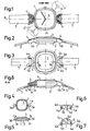
- the watch case consists of the middle section 1 and the base 2.
- the glass is labeled 3.
- Two diametrically opposed, radially outwardly projecting fastening tongues la T-shaped plan are formed on the circumference of the middle housing part 1.
- the T-crossbeams 1b are delimited by arc-shaped surfaces 1d, as a result of which the tongues 1a taper conically towards their ends facing away from the watch case.
- the connecting bodies 4 are designed as push-on caps.
- a fastening means for the bracelet 5 designed as a bracelet telescopic resilient spring webs 6 are used, the ends of which rest in blind holes 4a of the side walls 4b of the push-on caps 4.
- a slot 4d which is open at the bottom.
- the distance between the spring bars 6 and the surfaces 1d of the fastening tongues 1a running concentrically to these is selected such that that the corresponding areas of the loops 5a lie against the surfaces mentioned.
- the fastening of the bracelet loops 5a which is required anyway, eliminates the need for additional means and requires a special operation to secure the position of the push-on caps 4 against their push-on direction.
- the connecting body 4 is formed by receiving the T-shaped fastening tongue 1a in the opposite interior 4e of the connecting body 4 transversely to its push-on direction secured position. If the mutual intermeshing were to be accomplished by a different training of the same kind, and the fastening tongue was provided with a bore and the connection body configured as desired was to be engaged in the aforementioned bore with a projection formed on the underside thereof, this would also ensure the mutual securing of the position transversely to the direction of attachment of the Connection body ensured. In this regard, there are various training and design options.
- Fig. 8 is also indicated by dash-dotted lines that a one-piece bracelet 5 'can also run between the two spring bars 6 on the back of the housing.
- a short loop can first be set by means of the spring bar 6 in the manner shown, through which then z. B. a chain or collar is passed through.
- a collar-like support member can be attached directly.
- a housing type is to be used both for a wristwatch and as a pendulum clock, there are several options for conclusively securing the push-on cap of the fastening device not used in the latter type of use.
- the corresponding spring bar is made thicker in diameter or surrounded by a sleeve. Their cross section can be designed so that the free space surrounding the spring bar 6 of the push-on cap is completely filled in an aesthetic manner.
Landscapes
- Physics & Mathematics (AREA)
- General Physics & Mathematics (AREA)
- Adornments (AREA)
- Buckles (AREA)
- Electric Clocks (AREA)
- Telephone Function (AREA)
- Physical Vapour Deposition (AREA)
Claims (4)
Priority Applications (1)
| Application Number | Priority Date | Filing Date | Title |
|---|---|---|---|
| AT81810419T ATE12553T1 (de) | 1980-11-03 | 1981-10-22 | Gehaeuse fuer eine am koerper zu tragende uhr. |
Applications Claiming Priority (2)
| Application Number | Priority Date | Filing Date | Title |
|---|---|---|---|
| CH8142/80 | 1980-11-03 | ||
| CH814280A CH630500B (de) | 1980-11-03 | 1980-11-03 | Gehaeuse fuer eine am koerper zu tragende uhr. |
Publications (2)
| Publication Number | Publication Date |
|---|---|
| EP0051562A1 EP0051562A1 (fr) | 1982-05-12 |
| EP0051562B1 true EP0051562B1 (fr) | 1985-04-03 |
Family
ID=4335788
Family Applications (1)
| Application Number | Title | Priority Date | Filing Date |
|---|---|---|---|
| EP81810419A Expired EP0051562B1 (fr) | 1980-11-03 | 1981-10-22 | Boîtier pour montre portative |
Country Status (6)
| Country | Link |
|---|---|
| US (1) | US4466745A (fr) |
| EP (1) | EP0051562B1 (fr) |
| JP (1) | JPS57122802A (fr) |
| AT (1) | ATE12553T1 (fr) |
| CH (1) | CH630500B (fr) |
| DE (1) | DE3169723D1 (fr) |
Cited By (1)
| Publication number | Priority date | Publication date | Assignee | Title |
|---|---|---|---|---|
| CN108786078A (zh) * | 2018-06-25 | 2018-11-13 | 深圳市定尔志电子有限公司 | 一种体育用计时器佩戴装置 |
Families Citing this family (9)
| Publication number | Priority date | Publication date | Assignee | Title |
|---|---|---|---|---|
| EP0366613A1 (fr) * | 1988-10-27 | 1990-05-02 | Mondaine Watch Ltd | Boîtier de montre |
| US20100329084A1 (en) * | 2009-06-30 | 2010-12-30 | Shanker Mo | Clock Having Diverse Ornamental Variations |
| US8480247B2 (en) | 2011-04-27 | 2013-07-09 | Philip B. Fleet | Interchangeable decoration system |
| USD677586S1 (en) * | 2012-06-20 | 2013-03-12 | Venberg Sa | Watch |
| USD747994S1 (en) * | 2014-01-30 | 2016-01-26 | Glashütter Uhrenbetrieb GmbH | Watch dial |
| TWD169698S (zh) * | 2014-03-05 | 2015-08-11 | 哈利溫士頓公司 | 錶 |
| USD729098S1 (en) * | 2014-09-12 | 2015-05-12 | Harry Winston Sa | Dial |
| USD798741S1 (en) * | 2015-09-17 | 2017-10-03 | Graff Diamonds Sa | Watch |
| TWD208143S (zh) * | 2019-10-08 | 2020-11-11 | 瑞士商哈利溫士頓公司 | 錶殼 |
Family Cites Families (8)
| Publication number | Priority date | Publication date | Assignee | Title |
|---|---|---|---|---|
| CH204293A (fr) * | 1938-05-04 | 1939-04-30 | Ponti Gennari & Cie | Montre-bracelet. |
| US2344422A (en) * | 1940-03-04 | 1944-03-14 | Sickinger Helmut | Watchcase |
| CH318900A (fr) * | 1955-03-11 | 1957-01-31 | Marthaler Rene | Dispositif de fixation amovible de l'extrémité d'un lien à uno boîte de montre |
| US2775861A (en) * | 1955-10-24 | 1957-01-01 | Bulova Watch Co Inc | Wrist watch bracelet attachment |
| GB933969A (en) * | 1960-10-28 | 1963-08-14 | Theodor Engelhard | Improvements in or relating to strap attachments for wristwatches |
| US3165884A (en) * | 1962-11-14 | 1965-01-19 | Bulova Watch Co Inc | Watch band connector |
| US4231502A (en) * | 1978-08-15 | 1980-11-04 | Stanley Meyerson | Watch bracelet |
| US4266326A (en) * | 1979-08-06 | 1981-05-12 | Hong Lai F | Watchband connector |
-
1980
- 1980-11-03 CH CH814280A patent/CH630500B/de not_active IP Right Cessation
-
1981
- 1981-10-22 EP EP81810419A patent/EP0051562B1/fr not_active Expired
- 1981-10-22 AT AT81810419T patent/ATE12553T1/de not_active IP Right Cessation
- 1981-10-22 DE DE8181810419T patent/DE3169723D1/de not_active Expired
- 1981-11-02 JP JP56176320A patent/JPS57122802A/ja active Pending
- 1981-11-02 US US06/317,488 patent/US4466745A/en not_active Expired - Fee Related
Cited By (1)
| Publication number | Priority date | Publication date | Assignee | Title |
|---|---|---|---|---|
| CN108786078A (zh) * | 2018-06-25 | 2018-11-13 | 深圳市定尔志电子有限公司 | 一种体育用计时器佩戴装置 |
Also Published As
| Publication number | Publication date |
|---|---|
| CH630500B (de) | |
| JPS57122802A (en) | 1982-07-30 |
| EP0051562A1 (fr) | 1982-05-12 |
| CH630500GA3 (fr) | 1982-06-30 |
| US4466745A (en) | 1984-08-21 |
| ATE12553T1 (de) | 1985-04-15 |
| DE3169723D1 (en) | 1985-05-09 |
Similar Documents
| Publication | Publication Date | Title |
|---|---|---|
| DE69400724T2 (de) | Uhrengehäuse mit einem abnehmbaren Glasreif | |
| EP0051562A1 (fr) | Boîtier pour montre portative | |
| DE69938543T2 (de) | Chronographuhr aus Edelmetall mit einem ausgehöhlten Glasreif-Mittelteil | |
| DE1936655A1 (de) | Armbanduhr mit auswechselbarem Mittelteilglasreif | |
| DE8300471U1 (de) | Armbanduhr | |
| DE69312594T2 (de) | Armband, insbesondere uhrarmband | |
| DE69000211T2 (de) | Uhr mit einer vereinfachten ausstattung. | |
| EP0736824B1 (fr) | Boítier pour montre-bracelet | |
| WO1997039387A1 (fr) | Montre-bracelet | |
| EP0705731B1 (fr) | Feu de véhicule en particulier pour plaque d'immatriculation | |
| EP0639283B1 (fr) | Montre-bracelet | |
| DE69102317T2 (de) | Uhrengehäuse. | |
| DE7710598U1 (de) | Elektrische Glühlampenfassung | |
| DE29923612U1 (de) | Wechsel-Armbanduhr | |
| DE8804149U1 (de) | Fassungsträger für elektrische Lampen mit einem am Fassungsträger befestigten Reflektor | |
| DE3635529C2 (fr) | ||
| DE1134850B (de) | Uhrarmband fuer versteckten Bandanschluss am Uhrgehaeuse | |
| DE3220706A1 (de) | Uhr | |
| WO2004088437A2 (fr) | Bracelet montre et systeme bijou | |
| EP3641583B1 (fr) | Montre-bracelet et dispositif de bracelet pour une montre-bracelet | |
| EP0677797B1 (fr) | Montre-bracelet | |
| DE1903098U (de) | Gluhlampen-schraubfassung mit einem sicherungsglied zur rueckdrehsicherung. | |
| DE4409525A1 (de) | Sicherheitseinrichtung, insbesondere für Ohrschmuck | |
| DE2730930B1 (de) | Uhr, insbesondere wasserdichte armbanduhr | |
| DE202007004423U1 (de) | Schmuckband |
Legal Events
| Date | Code | Title | Description |
|---|---|---|---|
| PUAI | Public reference made under article 153(3) epc to a published international application that has entered the european phase |
Free format text: ORIGINAL CODE: 0009012 |
|
| AK | Designated contracting states |
Designated state(s): AT BE DE FR GB IT NL SE |
|
| KL | Correction list |
Free format text: 82/04 TITELBLATT |
|
| 17P | Request for examination filed |
Effective date: 19821015 |
|
| GRAA | (expected) grant |
Free format text: ORIGINAL CODE: 0009210 |
|
| AK | Designated contracting states |
Designated state(s): AT BE DE FR GB IT NL SE |
|
| PG25 | Lapsed in a contracting state [announced via postgrant information from national office to epo] |
Ref country code: NL Effective date: 19850403 Ref country code: IT Free format text: LAPSE BECAUSE OF FAILURE TO SUBMIT A TRANSLATION OF THE DESCRIPTION OR TO PAY THE FEE WITHIN THE PRESCRIBED TIME-LIMIT;WARNING: LAPSES OF ITALIAN PATENTS WITH EFFECTIVE DATE BEFORE 2007 MAY HAVE OCCURRED AT ANY TIME BEFORE 2007. THE CORRECT EFFECTIVE DATE MAY BE DIFFERENT FROM THE ONE RECORDED. Effective date: 19850403 Ref country code: FR Free format text: THE PATENT HAS BEEN ANNULLED BY A DECISION OF A NATIONAL AUTHORITY Effective date: 19850403 Ref country code: BE Effective date: 19850403 |
|
| REF | Corresponds to: |
Ref document number: 12553 Country of ref document: AT Date of ref document: 19850415 Kind code of ref document: T |
|
| PG25 | Lapsed in a contracting state [announced via postgrant information from national office to epo] |
Ref country code: SE Effective date: 19850430 |
|
| REF | Corresponds to: |
Ref document number: 3169723 Country of ref document: DE Date of ref document: 19850509 |
|
| NLV1 | Nl: lapsed or annulled due to failure to fulfill the requirements of art. 29p and 29m of the patents act | ||
| PG25 | Lapsed in a contracting state [announced via postgrant information from national office to epo] |
Ref country code: AT Effective date: 19851022 |
|
| EN | Fr: translation not filed | ||
| PLBE | No opposition filed within time limit |
Free format text: ORIGINAL CODE: 0009261 |
|
| STAA | Information on the status of an ep patent application or granted ep patent |
Free format text: STATUS: NO OPPOSITION FILED WITHIN TIME LIMIT |
|
| 26N | No opposition filed | ||
| GBPC | Gb: european patent ceased through non-payment of renewal fee | ||
| PG25 | Lapsed in a contracting state [announced via postgrant information from national office to epo] |
Ref country code: DE Effective date: 19870701 |
|
| PG25 | Lapsed in a contracting state [announced via postgrant information from national office to epo] |
Ref country code: GB Effective date: 19881118 |