EP0051680B1 - Caisson de suppression d'ondes - Google Patents
Caisson de suppression d'ondes Download PDFInfo
- Publication number
- EP0051680B1 EP0051680B1 EP81901128A EP81901128A EP0051680B1 EP 0051680 B1 EP0051680 B1 EP 0051680B1 EP 81901128 A EP81901128 A EP 81901128A EP 81901128 A EP81901128 A EP 81901128A EP 0051680 B1 EP0051680 B1 EP 0051680B1
- Authority
- EP
- European Patent Office
- Prior art keywords
- wing pieces
- pair
- bottom wall
- trapezoidal
- caisson
- Prior art date
- Legal status (The legal status is an assumption and is not a legal conclusion. Google has not performed a legal analysis and makes no representation as to the accuracy of the status listed.)
- Expired
Links
Images
Classifications
-
- E—FIXED CONSTRUCTIONS
- E02—HYDRAULIC ENGINEERING; FOUNDATIONS; SOIL SHIFTING
- E02B—HYDRAULIC ENGINEERING
- E02B3/00—Engineering works in connection with control or use of streams, rivers, coasts, or other marine sites; Sealings or joints for engineering works in general
- E02B3/04—Structures or apparatus for, or methods of, protecting banks, coasts, or harbours
- E02B3/12—Revetment of banks, dams, watercourses, or the like, e.g. the sea-floor
- E02B3/129—Polyhedrons, tetrapods or similar bodies, whether or not threaded on strings
-
- Y—GENERAL TAGGING OF NEW TECHNOLOGICAL DEVELOPMENTS; GENERAL TAGGING OF CROSS-SECTIONAL TECHNOLOGIES SPANNING OVER SEVERAL SECTIONS OF THE IPC; TECHNICAL SUBJECTS COVERED BY FORMER USPC CROSS-REFERENCE ART COLLECTIONS [XRACs] AND DIGESTS
- Y02—TECHNOLOGIES OR APPLICATIONS FOR MITIGATION OR ADAPTATION AGAINST CLIMATE CHANGE
- Y02A—TECHNOLOGIES FOR ADAPTATION TO CLIMATE CHANGE
- Y02A10/00—TECHNOLOGIES FOR ADAPTATION TO CLIMATE CHANGE at coastal zones; at river basins
- Y02A10/11—Hard structures, e.g. dams, dykes or breakwaters
Definitions
- This invention relates to a permeable wave dissipation caisson preferably, made of concrete, and placed on a seabed to dissipate the energy of waves passing therethrough.
- obstruction of the movement of waves by the blocks prevents the alternating flow of seawater through the blocks, which causes corruption of the seawater.
- the present invention has the purpose of providing a caisson which not only improves the alternating flow of seawater therethrough but also can be utilized as a fishing rock owing to its permeable structure.
- a water current control block which may also be utilized for absorbing wave energy along seashores, has been described in US Patent No. 3,386,250 (SUSUMU KATAYAMA).
- This water control block is hollow tetrahedral body, each of the four sides thereof being in the same shape of an isosceles triangle and having an opening communicating with the interior of said body. While such hollow body has a certain ability of absorbing wave energy, there is a need for a wave dissipation device having a still greater efficiency of absorption of wave energy.
- the above mentioned tetrahedral body suffers from the drawback that it cannot easily be piled up in a stable manner.
- the present invention is intended to provide a caisson which has a very high efficiency of absorption of wave energy and which can be piled one atop the other due to its box-shaped structure.
- a wave dissipation caisson consisting of a hollow body, delimited by walls having openings which communicate with the interior of said body
- said caisson being characterized in that it comprises: a frame having a bottom wall adapted to rest on the floor of a body of water said bottom wall having a plurality of openings therethrough, said frame including a plurality of vertical frame members extending upwardly from said bottom wall and a plurality of horizontal frame members connected to said vertical frame members to form open sides and an open top of said frame; a first pair of trapezoidal wing pieces each having a large edge and a small edge, said first pair of trapezoidal wing pieces being connected to each other at said small edges thereof and diverging outwardly toward said large edges thereof; and a second pair of trapezoidal wing pieces each having a large edge and small edge, said second pair of trapezoidal wing pieces being connected to each other at said small edges thereof and diverging outwardly toward said large edges thereof; each of said wing pieces having a plurality of
- the waves entering the caisson as shown by an arrow in Fig. 1 of the attached drawings are deflected and divided in the vertical direction A and in the horizontal direction B by openings provided in the wing body and are further broken up vertically and horizontally by the rear wing body joined to the front wing body at an angle of 90°.
- the waves are broken up and made turbulent in the caisson and thereby the energy of the waves is scattered and dissipated completely.
- the holes made in the bottom wall absorb the energy of waves, whereby the possibility of the caisson being upset by the waves is eliminated.
- the existence of the bottom wall in addition to the holes prevents the waves from penetrating into the place wherein the caisson is installed and from digging up the seabed at this place, whereby the stability of the installed caisson can be maintained.
- the caisson since the caisson has a permeable structure and, in addition, each wind piece is provided with holes, the ratio of a space inside the caisson is high and this makes the caisson inhabitable for fish and shellfish. Therefore, the caisson may also be utilized as a fishing rock.
- the caisson in the present invention does not obstruct the alternating flow of seawater through the caisson, whereby the corruption of the seawater at the back of the caisson is prevented. Moreover, the condition of the box-type caisson makes it easy to pile it up, and thus stable piling thereof can be assured.
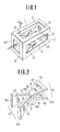
- Figure 1 is a perspective view of the wave dissipation caisson which is an embodiment of the present invention
- Figure 2 is a perspective view of the structure of junction of two sets of wing bodies forms part of the wave dissipation caisson.
- Fig. 1 shows an embodiment of the wave dissipation caisson of the present invention, which is made of concrete.
- the box-type frame- is a frame wherein no closed side and upper walls are provided but only a bottom surface wall 5 is provided.
- the upper parts thereof are constituted only by angled sections of a framework.
- a set of two trapezoidal wing pieces 2 and 3 is arranged as shown in Fig. 2.
- the smaller sides or edges 2b and 3b of the wing pieces are made to face each other and are joined to form a wing body 4.
- the smaller sides or edges of two trapezoidal wing pieces 6 and 7 are also made to face each other in the same manner and joined to form the other wing body 8.
- the opposed parts 4b and 8b of the two wing bodies 4 and 8 are joined to each other in their shown positions at an angle of 90° to each other, and a structure thus constituted is housed in and fixed to the frame.
- the fixation is made in such a manner that the larger sides of each wing body are fixed to the respective angled sections of the framework, that is, the larger sides 2a and 3a of the wing body 4 are fixed to the angled sections or frame members 9 and 10 of the framework and the larger sides 6a and 7a of the other wing body 8 to the horizontal angled sections or frame members 11 and 12 thereof.
- Frame member 11 is formed by one edge of wall 5.
- the wave dissipation caisson of the present invention can be used as a breakwater, a revet- ment or a pier in a harbour, on a coast and in a river, as well as for the use as a fishing rock which is inhabitable by fish.
Landscapes
- Engineering & Computer Science (AREA)
- General Engineering & Computer Science (AREA)
- Chemical & Material Sciences (AREA)
- Crystallography & Structural Chemistry (AREA)
- Inorganic Chemistry (AREA)
- Environmental & Geological Engineering (AREA)
- Ocean & Marine Engineering (AREA)
- Mechanical Engineering (AREA)
- Civil Engineering (AREA)
- Structural Engineering (AREA)
- Revetment (AREA)
Abstract
Claims (3)
Applications Claiming Priority (2)
| Application Number | Priority Date | Filing Date | Title |
|---|---|---|---|
| JP624080A JPS55101549A (en) | 1979-01-23 | 1980-01-22 | Pallet assembly |
| JP6240/80 | 1980-05-09 |
Publications (3)
| Publication Number | Publication Date |
|---|---|
| EP0051680A1 EP0051680A1 (fr) | 1982-05-19 |
| EP0051680A4 EP0051680A4 (fr) | 1983-03-15 |
| EP0051680B1 true EP0051680B1 (fr) | 1985-08-21 |
Family
ID=11632975
Family Applications (1)
| Application Number | Title | Priority Date | Filing Date |
|---|---|---|---|
| EP81901128A Expired EP0051680B1 (fr) | 1980-01-22 | 1981-04-24 | Caisson de suppression d'ondes |
Country Status (1)
| Country | Link |
|---|---|
| EP (1) | EP0051680B1 (fr) |
Families Citing this family (3)
| Publication number | Priority date | Publication date | Assignee | Title |
|---|---|---|---|---|
| FR2579643B1 (fr) * | 1985-03-29 | 1987-11-20 | Rixain Henri | Module de realisation de structures destinees a etre immerge pour former des recifs artificiels |
| BR8707729A (pt) * | 1987-04-21 | 1989-10-17 | Nobuhiko Iwasa | Processo de produzir um caixao dissipador de onda e o respectivo caixao dissipador de onda |
| DE59108012D1 (de) * | 1990-04-10 | 1996-08-29 | Buesching Fritz | Uferschutzbauwerk |
Family Cites Families (4)
| Publication number | Priority date | Publication date | Assignee | Title |
|---|---|---|---|---|
| GB683360A (en) * | 1950-03-10 | 1952-11-26 | Neyrpic Ets | Improvements in or relating to artificial blocks for the protection of structures exposed to the action of moving water |
| US3386250A (en) * | 1963-12-07 | 1968-06-04 | Katayama Susumu | Water current controlling means |
| US3898958A (en) * | 1974-06-13 | 1975-08-12 | Jr Peter P Pranis | Open water fish farming apparatus |
| US4165711A (en) * | 1976-06-07 | 1979-08-28 | Koichiro Aoki | Fish-gathering block |
-
1981
- 1981-04-24 EP EP81901128A patent/EP0051680B1/fr not_active Expired
Non-Patent Citations (1)
| Title |
|---|
| CEMENT, vol. 24, no. 12, December 1972 J.F. AGEMA: "Havendammen aan zee", pages 511-514 * |
Also Published As
| Publication number | Publication date |
|---|---|
| EP0051680A1 (fr) | 1982-05-19 |
| EP0051680A4 (fr) | 1983-03-15 |
Similar Documents
| Publication | Publication Date | Title |
|---|---|---|
| US4431337A (en) | Wave dissipation caisson | |
| US3118282A (en) | Breakwater structures | |
| US3952521A (en) | Portable floating wave tripper | |
| US4836709A (en) | Water wave absorber | |
| EP0051680B1 (fr) | Caisson de suppression d'ondes | |
| CN107558436B (zh) | 一种用于浅水域高效削减长周期波的柔性消波装置 | |
| EP0310666A1 (fr) | Caisson de dissipation d'ondes et procede de production dudit caisson | |
| KR20190025119A (ko) | 중량체와 결합되는 잠제(潛堤)형 해양침식방지 개비온 | |
| CN207435996U (zh) | 一种用于浅水域高效削减长周期波的柔性消波装置 | |
| KR100975905B1 (ko) | 소파 구조물 및 이의 설치방법 | |
| KR100815290B1 (ko) | 물고기집이 설치된 옹벽블럭조립체 | |
| JP2001120107A (ja) | 海藻育成装置 | |
| KR101568264B1 (ko) | 파향 전환기능을 갖는 잠제블록 | |
| JP3063057B2 (ja) | 生態系保全用連結ブロック護岸 | |
| JPH06212611A (ja) | 防波堤 | |
| JPS6213605A (ja) | 透過性防波堤 | |
| KR100764915B1 (ko) | 연장벽체를 포함하는 저중심형 부방파제 | |
| CN223497110U (zh) | 具有消浪功能的护岸结构 | |
| JPS5883711A (ja) | 離岸堤の施工法 | |
| JP3112741B2 (ja) | 防波堤 | |
| KR200318100Y1 (ko) | 생태계 보호용 하천 호안 시설물 | |
| JPH0860634A (ja) | 海底固定式透過型消波堤 | |
| JPH0799011B2 (ja) | 海域制御構造物 | |
| JPH0860635A (ja) | 港湾等の消波構造体 | |
| JPS5941528A (ja) | ケ−ソン |
Legal Events
| Date | Code | Title | Description |
|---|---|---|---|
| PUAI | Public reference made under article 153(3) epc to a published international application that has entered the european phase |
Free format text: ORIGINAL CODE: 0009012 |
|
| AK | Designated contracting states |
Designated state(s): FR |
|
| 17P | Request for examination filed |
Effective date: 19820511 |
|
| GRAA | (expected) grant |
Free format text: ORIGINAL CODE: 0009210 |
|
| AK | Designated contracting states |
Designated state(s): FR |
|
| ET | Fr: translation filed | ||
| PLBE | No opposition filed within time limit |
Free format text: ORIGINAL CODE: 0009261 |
|
| STAA | Information on the status of an ep patent application or granted ep patent |
Free format text: STATUS: NO OPPOSITION FILED WITHIN TIME LIMIT |
|
| 26N | No opposition filed | ||
| REG | Reference to a national code |
Ref country code: FR Ref legal event code: ST |
|
| REG | Reference to a national code |
Ref country code: FR Ref legal event code: AR |
|
| REG | Reference to a national code |
Ref country code: FR Ref legal event code: BR |
|
| PGFP | Annual fee paid to national office [announced via postgrant information from national office to epo] |
Ref country code: FR Payment date: 19891030 Year of fee payment: 9 |
|
| PG25 | Lapsed in a contracting state [announced via postgrant information from national office to epo] |
Ref country code: FR Effective date: 19901228 |
|
| REG | Reference to a national code |
Ref country code: FR Ref legal event code: ST |