EP0051747A1 - Appareil pour l'élimination de verrues utilisant l'azote liquide - Google Patents
Appareil pour l'élimination de verrues utilisant l'azote liquide Download PDFInfo
- Publication number
- EP0051747A1 EP0051747A1 EP81108004A EP81108004A EP0051747A1 EP 0051747 A1 EP0051747 A1 EP 0051747A1 EP 81108004 A EP81108004 A EP 81108004A EP 81108004 A EP81108004 A EP 81108004A EP 0051747 A1 EP0051747 A1 EP 0051747A1
- Authority
- EP
- European Patent Office
- Prior art keywords
- temperature
- cooling rod
- handle
- liquid nitrogen
- treatment
- Prior art date
- Legal status (The legal status is an assumption and is not a legal conclusion. Google has not performed a legal analysis and makes no representation as to the accuracy of the status listed.)
- Withdrawn
Links
- IJGRMHOSHXDMSA-UHFFFAOYSA-N Atomic nitrogen Chemical compound N#N IJGRMHOSHXDMSA-UHFFFAOYSA-N 0.000 title claims abstract description 40
- 229910052757 nitrogen Inorganic materials 0.000 title claims abstract description 20
- 239000007788 liquid Substances 0.000 title claims abstract description 19
- 238000001816 cooling Methods 0.000 claims abstract description 58
- 238000005259 measurement Methods 0.000 claims description 3
- 238000009529 body temperature measurement Methods 0.000 abstract description 2
- 208000000260 Warts Diseases 0.000 description 18
- 201000010153 skin papilloma Diseases 0.000 description 18
- RYGMFSIKBFXOCR-UHFFFAOYSA-N Copper Chemical compound [Cu] RYGMFSIKBFXOCR-UHFFFAOYSA-N 0.000 description 6
- 229910052802 copper Inorganic materials 0.000 description 6
- 239000010949 copper Substances 0.000 description 6
- 239000004033 plastic Substances 0.000 description 4
- 229920000742 Cotton Polymers 0.000 description 3
- 238000003825 pressing Methods 0.000 description 3
- 230000003287 optical effect Effects 0.000 description 2
- 230000004913 activation Effects 0.000 description 1
- XAGFODPZIPBFFR-UHFFFAOYSA-N aluminium Chemical compound [Al] XAGFODPZIPBFFR-UHFFFAOYSA-N 0.000 description 1
- 230000004397 blinking Effects 0.000 description 1
- 238000005266 casting Methods 0.000 description 1
- 150000001875 compounds Chemical class 0.000 description 1
- 230000000881 depressing effect Effects 0.000 description 1
- 238000011161 development Methods 0.000 description 1
- 230000018109 developmental process Effects 0.000 description 1
- 239000011152 fibreglass Substances 0.000 description 1
- 238000003780 insertion Methods 0.000 description 1
- 230000037431 insertion Effects 0.000 description 1
- 238000000034 method Methods 0.000 description 1
- 230000035515 penetration Effects 0.000 description 1
- 239000004848 polyfunctional curative Substances 0.000 description 1
- 239000000843 powder Substances 0.000 description 1
- 239000010453 quartz Substances 0.000 description 1
- VYPSYNLAJGMNEJ-UHFFFAOYSA-N silicon dioxide Inorganic materials O=[Si]=O VYPSYNLAJGMNEJ-UHFFFAOYSA-N 0.000 description 1
- 238000002791 soaking Methods 0.000 description 1
- 239000000057 synthetic resin Substances 0.000 description 1
- 229920003002 synthetic resin Polymers 0.000 description 1
- 230000001960 triggered effect Effects 0.000 description 1
- 238000009834 vaporization Methods 0.000 description 1
- 230000008016 vaporization Effects 0.000 description 1
- 210000002268 wool Anatomy 0.000 description 1
Images
Classifications
-
- A—HUMAN NECESSITIES
- A61—MEDICAL OR VETERINARY SCIENCE; HYGIENE
- A61B—DIAGNOSIS; SURGERY; IDENTIFICATION
- A61B18/00—Surgical instruments, devices or methods for transferring non-mechanical forms of energy to or from the body
- A61B18/02—Surgical instruments, devices or methods for transferring non-mechanical forms of energy to or from the body by cooling, e.g. cryogenic techniques
-
- A—HUMAN NECESSITIES
- A61—MEDICAL OR VETERINARY SCIENCE; HYGIENE
- A61B—DIAGNOSIS; SURGERY; IDENTIFICATION
- A61B17/00—Surgical instruments, devices or methods
- A61B2017/00743—Type of operation; Specification of treatment sites
- A61B2017/00747—Dermatology
- A61B2017/00774—Wart
Definitions
- the invention relates to a device for the removal of warts with liquid nitrogen, which essentially consists of a metallic cooling rod, inside which a temperature sensor is arranged, which can be connected to an electrical temperature measuring device.
- the cotton swab Since the duration of the treatment is usually one to two minutes, the cotton swab has to be soaked several times with liquid nitrogen. The inevitable interruption of the cold supply to the wart has proven to be disadvantageous.
- the invention has for its object to provide a device consisting essentially of a metallic cooling rod for the removal of warts with liquid nitrogen, which avoids any cable connection and allows the treating doctor, despite constant temperature control, to devote his full attention to the actual treatment.
- the devices for temperature control are arranged on the handle according to the invention in such a way that the treating physician can keep an eye on them simultaneously with the object to be treated. If the temperature is controlled by acoustic aids, these can also be attached to other parts of the handle. There are many options for displaying the temperature range. For example, an excessively high temperature can be indicated by a flashing red LED, a sufficiently low temperature by a flashing green LED. A sufficiently low temperature can be acoustically indicated, for example by a beep, which ends when the cooling rod becomes too warm.
- the device according to the invention prevents the attending physician from having to divide his attention between the object to be treated and a temperature measuring device.
- the temperature measuring device and temperature display are located in or on the handle, there is no need for any cable connection and thus the cumbersome removal of the cable connection and insertion of the cooling rod into an insulating tube.
- the cooling rod and the handle are advantageously designed in such a way that the cooling rod can be latched into or removed from the handle by slight pressure or tension, the attending physician can carry out these actions with one hand. Removing the cooling rod can e.g. so that it is held by a pull-off ring on the edge of the vessel with liquid nitrogen, from which it falls into the vessel with liquid nitrogen after the cooling rod has been removed from the handle.
- the cooling rod can be latched into the handle in a similarly simple manner by pressing the handle onto the free end of the cooling rod protruding from the container with liquid nitrogen.
- an electrically conductive connection between the temperature sensor in the tip of the cooling rod and the temperature measuring device in the interior of the handle is simultaneously established.
- This temperature measuring device consists of a circuit board with electronic components. The device can be designed in such a way that the temperature display is activated immediately after the cooling rod has clicked in. This activation can also be triggered by a micro button on the handle.
- the easy interchangeability of the cooling rod with only one hand is a further advantage of the device according to the invention. It is particularly advantageous if the treatment of the wart extends over several minutes and freshly cooled cooling rods have to be pressed onto the wart several times. The cooling system can then be replaced so quickly that there is no significant interruption to the treatment.
- a device for measuring time is therefore additionally arranged on the handle.
- This device can be integrated in the circuit board with the electronic components for temperature measurement. For shorter treatment times, it is sufficient to provide, for example, an LED that flashes every 5 seconds. For treatment times of more than 1 minute, on the other hand, it is cheaper to install a quartz watch in the handle for time measurement, which shows the elapsed treatment time.
- an auxiliary device can also be provided with which a desired treatment duration is preprogrammed. The end of the pre-programmed treatment time is indicated by an optical or acoustic signal.
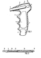
- the pistol-like handle 1 shown in FIG. 1 serves as a holding device for the cooling rod. It is preferably made of plastic or a casting compound based on plastic, e.g. made of plastic powder, aluminum powder, fiberglass wool, liquid synthetic resin and a hardener.
- the tube guide sleeve 2 In the upper part of the hollow handle 1 is the tube guide sleeve 2 for receiving the cooling rod.
- the pipe guide sleeve 2 ends in a plug connection 3, into which the cooling rod latches when it is inserted.
- the temperature sensor 4 of the cooling rod shown in FIG. 2 is connected to the electronic temperature measuring device inside the handle 1.
- This temperature measuring device is only indicated schematically and consists essentially of a circuit board 5 with electronic components.
- the power supply is provided by a battery located in the battery compartment 6.
- the circuit By pressing the micro button 7, the circuit is closed and the device is activated.
- the temperature is indicated by a red LED 8 and a green LED 9.
- the LED 8 emits a red flashing light. If, on the other hand, the temperature of the cooling rod is sufficiently low, the green light diode 9 flashes.
- the circuitry required for this purpose of the electronic components on the circuit board 5 is known and is therefore not shown in detail.
- a yellow light-emitting diode 10 is also provided, which flashes every five seconds, so that the treating doctor can inform himself about the elapsed treatment time by counting the blinking processes.
- the components required for the light emitting diode 10 are integrated in the circuit board 5.
- the cooling rod shown in Figure 2 has a connector 11 as a counterpart to the connector 3 of the handle 1.
- the actual cooling rod consists of a partially hollow copper rod 12, the tip 13 is tapered.
- the temperature sensor 4 for example a resistance thermometer, is located in the cavity of the copper rod 12.
- the copper rod 12 is connected to the plug connection 11 by a plastic tube 14.
- the temperature sensor 4 is connected to the plug connection 11 by a cable 15.
- cooling rods are kept ready for working with the device according to the invention. These cooling rods can also have tips 13 with different diameters.
- the cooling rods are placed in a vessel with liquid nitrogen so that the copper rods 12 are completely surrounded by nitrogen.
- the cooling rods are cold enough as soon as the violent nitrogen vaporization has stopped.
- the handle 1 is connected to the desired cooling rod by pushing the pipe guide sleeve 2 over the cooling rod until the plug connections 3 and 11 are connected to one another by latching.
- the cooling rod is now firmly seated in handle 1 and can be removed from the container with liquid nitrogen. Depressing the micro button 7 closes the circuit between the temperature sensor 4, the circuit board 5, the battery in the battery compartment 6 and the light-emitting diodes 8, 9 and 10.
- the corresponding cable connections have not been shown in Fig.1.
- the LED 9 emits a green flashing light, which indicates that the copper rod 12 has a sufficiently low temperature, for example between -196 ° C, the temperature of the liquid nitrogen, and -150 ° C. As long as the micro button 7 is pressed down, the LED 10 lights up yellow every five seconds. The removal of the wart can now begin by placing the cooling rod with the tip 13 on the wart.
- the duration of treatment is checked with the LED 10. As soon as the cooling rod has become warmer than -150 ° C, the green LED 9 goes out and the LED 8 flashes red. The cooling rod must now be removed, which can be done in a simple manner using a pull-off ring on the container with liquid nitrogen. The cooling rod falls back into the container and, as described, a sufficiently cold new cooling rod is inserted into the pipe guide sleeve 2. It takes only a few seconds to replace the cooling rods, so that the treatment of the wart is not interrupted to any significant extent.
Landscapes
- Health & Medical Sciences (AREA)
- Surgery (AREA)
- Life Sciences & Earth Sciences (AREA)
- Nuclear Medicine, Radiotherapy & Molecular Imaging (AREA)
- Medical Informatics (AREA)
- Engineering & Computer Science (AREA)
- Biomedical Technology (AREA)
- Heart & Thoracic Surgery (AREA)
- Otolaryngology (AREA)
- Molecular Biology (AREA)
- Animal Behavior & Ethology (AREA)
- General Health & Medical Sciences (AREA)
- Public Health (AREA)
- Veterinary Medicine (AREA)
- Thermotherapy And Cooling Therapy Devices (AREA)
- Measuring And Recording Apparatus For Diagnosis (AREA)
Applications Claiming Priority (2)
| Application Number | Priority Date | Filing Date | Title |
|---|---|---|---|
| DE19803042202 DE3042202A1 (de) | 1980-11-08 | 1980-11-08 | Geraet zur entfernung von warzen mit fluessigstickstoff |
| DE3042202 | 1980-11-08 |
Publications (1)
| Publication Number | Publication Date |
|---|---|
| EP0051747A1 true EP0051747A1 (fr) | 1982-05-19 |
Family
ID=6116304
Family Applications (1)
| Application Number | Title | Priority Date | Filing Date |
|---|---|---|---|
| EP81108004A Withdrawn EP0051747A1 (fr) | 1980-11-08 | 1981-10-07 | Appareil pour l'élimination de verrues utilisant l'azote liquide |
Country Status (4)
| Country | Link |
|---|---|
| EP (1) | EP0051747A1 (fr) |
| DE (1) | DE3042202A1 (fr) |
| ES (1) | ES506876A0 (fr) |
| ZA (1) | ZA817669B (fr) |
Citations (7)
| Publication number | Priority date | Publication date | Assignee | Title |
|---|---|---|---|---|
| DE2037900A1 (de) * | 1970-07-24 | 1972-02-03 | Deutsche Endoskopbau Gesellschaft Sass, Wolf & Co mbH, 1000 Berlin | Sonde für die Kryochirurgie |
| DE2214703A1 (de) * | 1972-03-25 | 1973-10-04 | Leybold Heraeus Gmbh & Co Kg | Schaltung zur ueberwachung von temperaturfuehlern in kryomedizinischen instrumenten |
| DE2258333A1 (de) * | 1972-11-29 | 1974-05-30 | Draegerwerk Ag | Kryomedizinische sonde zur prostatabehandlung |
| US3823575A (en) * | 1971-06-07 | 1974-07-16 | Univ Melbourne | Cryogenic apparatus |
| US4121462A (en) * | 1976-02-09 | 1978-10-24 | La Barge, Inc. | Temperature indicating apparatus |
| US4174631A (en) * | 1978-01-09 | 1979-11-20 | Temp-Stik Corporation | Clinical thermometer with thermo-couple probe |
| DE2925270A1 (de) * | 1978-06-23 | 1980-01-10 | Bracco Dario | Cryotherapeutische vorrichtung |
-
1980
- 1980-11-08 DE DE19803042202 patent/DE3042202A1/de not_active Ceased
-
1981
- 1981-10-07 EP EP81108004A patent/EP0051747A1/fr not_active Withdrawn
- 1981-11-05 ES ES506876A patent/ES506876A0/es active Granted
- 1981-11-06 ZA ZA817669A patent/ZA817669B/xx unknown
Patent Citations (8)
| Publication number | Priority date | Publication date | Assignee | Title |
|---|---|---|---|---|
| DE2037900A1 (de) * | 1970-07-24 | 1972-02-03 | Deutsche Endoskopbau Gesellschaft Sass, Wolf & Co mbH, 1000 Berlin | Sonde für die Kryochirurgie |
| US3823575A (en) * | 1971-06-07 | 1974-07-16 | Univ Melbourne | Cryogenic apparatus |
| DE2214703A1 (de) * | 1972-03-25 | 1973-10-04 | Leybold Heraeus Gmbh & Co Kg | Schaltung zur ueberwachung von temperaturfuehlern in kryomedizinischen instrumenten |
| DE2258333A1 (de) * | 1972-11-29 | 1974-05-30 | Draegerwerk Ag | Kryomedizinische sonde zur prostatabehandlung |
| US4121462A (en) * | 1976-02-09 | 1978-10-24 | La Barge, Inc. | Temperature indicating apparatus |
| US4174631A (en) * | 1978-01-09 | 1979-11-20 | Temp-Stik Corporation | Clinical thermometer with thermo-couple probe |
| DE2925270A1 (de) * | 1978-06-23 | 1980-01-10 | Bracco Dario | Cryotherapeutische vorrichtung |
| GB2026324A (en) * | 1978-06-23 | 1980-02-06 | Bracco D | Cryotherapy apparatus |
Also Published As
| Publication number | Publication date |
|---|---|
| DE3042202A1 (de) | 1982-05-19 |
| ES8207422A1 (es) | 1982-10-01 |
| ES506876A0 (es) | 1982-10-01 |
| ZA817669B (en) | 1983-07-27 |
Similar Documents
| Publication | Publication Date | Title |
|---|---|---|
| DE68906007T2 (de) | Injektionsvorrichtung fuer medizinischen und tieraerztlichen gebrauch, die infektionen verhindert. | |
| DE60018018T2 (de) | Elektronische Lanzette | |
| DE2724324C2 (de) | Vorrichtung zum Zertrümmern von Blasensteinen | |
| DE3719353A1 (de) | Elektrischer stimulator fuer nerven | |
| DE10217929A1 (de) | Vorrichtung zur Ausgabe von Tabletten | |
| EP0013421A1 (fr) | Dispositif pour la localisation de personnes | |
| DE112004000761T5 (de) | Vorrichtung zur Kallus-Elongation/Regeneration | |
| EP0302278A1 (fr) | Dispositif d'injection | |
| DE1944087A1 (de) | Halbleiterstrahlungsdetektor als Katheter | |
| DE9100366U1 (de) | Behandlungsstift zur Stimulation von Akupunkturpunkten | |
| EP0051747A1 (fr) | Appareil pour l'élimination de verrues utilisant l'azote liquide | |
| EP0318709A1 (fr) | Dispositif pour extraire les racines de dents fracturées | |
| DE1276290B (de) | Einrichtung zur Durchfuehrung von Impfungen gegen Pocken oder andere Viruskrankheiten | |
| DE2937598A1 (de) | Verfahren und vorrichtung zur vorprogrammierbaren bestrahlung von personen | |
| DE69433986T2 (de) | Visuell gesteuerter trokar | |
| DE10254668A1 (de) | Gerät zur Behandlung von Gefäßdefekten | |
| DE3040524A1 (de) | Pulsmessvorrichtung | |
| DE102004018340B4 (de) | Positioniereinrichtung zur Anbringung einer Stimulationseinrichtung am Körper eines Organismus, Behandlungsvorrichtung zur äußeren Stimulation des Organismus, medizinisches Gerät und Verfahren zur Signalübertragung | |
| DE2061593C3 (de) | Vorrichtung zum Ansetzen eines Messkopfes in einer Höhle des menschlichen Körpers | |
| DE9015639U1 (de) | Suchgerät für Zahnimplantate | |
| DE102022116282A1 (de) | Vorrichtung zum Benetzen des Auges und Verfahren dazu | |
| DE29519433U1 (de) | Lichtakupunktur-Behandlungsgerät | |
| DE10147157A1 (de) | Bildgebendes System mit Aufnahmezeitanzeigevorrichtung | |
| DE3935969C1 (en) | Fitting plugs in lobes of ears - involves single actuator connected to plug insertion equipment by Bowden cables | |
| DE824087C (de) | Geraet zur tropfenweisen Blutentnahme (sog. Schnepper) |
Legal Events
| Date | Code | Title | Description |
|---|---|---|---|
| PUAI | Public reference made under article 153(3) epc to a published international application that has entered the european phase |
Free format text: ORIGINAL CODE: 0009012 |
|
| AK | Designated contracting states |
Designated state(s): AT BE CH FR GB NL SE |
|
| 17P | Request for examination filed |
Effective date: 19820407 |
|
| STAA | Information on the status of an ep patent application or granted ep patent |
Free format text: STATUS: THE APPLICATION IS DEEMED TO BE WITHDRAWN |
|
| 18D | Application deemed to be withdrawn |
Effective date: 19840723 |
|
| RIN1 | Information on inventor provided before grant (corrected) |
Inventor name: WEINKNECHT, BERND Inventor name: VOLKER, WOLFGANG Inventor name: JANKOWSKI, DETLEF |