EP0051815B2 - Pump comprising locking means for a flexible tube - Google Patents
Pump comprising locking means for a flexible tube Download PDFInfo
- Publication number
- EP0051815B2 EP0051815B2 EP81109187A EP81109187A EP0051815B2 EP 0051815 B2 EP0051815 B2 EP 0051815B2 EP 81109187 A EP81109187 A EP 81109187A EP 81109187 A EP81109187 A EP 81109187A EP 0051815 B2 EP0051815 B2 EP 0051815B2
- Authority
- EP
- European Patent Office
- Prior art keywords
- tube
- pump
- inlet
- organs
- outlet
- Prior art date
- Legal status (The legal status is an assumption and is not a legal conclusion. Google has not performed a legal analysis and makes no representation as to the accuracy of the status listed.)
- Expired - Lifetime
Links
- 210000000056 organ Anatomy 0.000 claims abstract description 19
- 210000004072 lung Anatomy 0.000 description 3
- 230000017531 blood circulation Effects 0.000 description 1
- 239000007788 liquid Substances 0.000 description 1
- 229920003023 plastic Polymers 0.000 description 1
- 238000001356 surgical procedure Methods 0.000 description 1
- 210000003813 thumb Anatomy 0.000 description 1
Images
Classifications
-
- F—MECHANICAL ENGINEERING; LIGHTING; HEATING; WEAPONS; BLASTING
- F04—POSITIVE - DISPLACEMENT MACHINES FOR LIQUIDS; PUMPS FOR LIQUIDS OR ELASTIC FLUIDS
- F04B—POSITIVE-DISPLACEMENT MACHINES FOR LIQUIDS; PUMPS
- F04B43/00—Machines, pumps, or pumping installations having flexible working members
- F04B43/12—Machines, pumps, or pumping installations having flexible working members having peristaltic action
- F04B43/1253—Machines, pumps, or pumping installations having flexible working members having peristaltic action by using two or more rollers as squeezing elements, the rollers moving on an arc of a circle during squeezing
Definitions
- the tube is usually locked by means of especially designed inserts which are adapted to lock the tube against a seat at the inlet and outlet, respectively.
- inserts are mounted on the pump by means of some form of screw joint and dimensioned such that they fit only one tube dimension at a time.
- the known device according to FR-A-2 321 147 includes only details which are similar to corresponding details of our present device, but differs basically from our device since this known device does not include simultaneously mowable organs for locking the tube at the inlet and the outlet of the pump. According to the FR-A-2 321 147 such locking organs 6, 6 (see for example Fig. 1 ) are not simultaneously operable but must be moved separately by means of separate thumb screws 5, 5. Consequently, a tube exchange in this known device is more complicated and takes also a longer time than a corresponding tube exchange in our present device, since one has to consecutively loosen the locking organs 6, 6 in this known device. According to our present device this can be done in one step and simultaneously.
- the pump according to the present invention may conveniently be housed in an essentially rectangular box 1 comprising a cup-shaped bottom portion 2 and to an openable and closable lid 3.
- said lid 3 has a central opening 4 which may be covered by for example a transparent plastic cover 5, whereby it is possible to supervise the pump without the need to open the lid.
Landscapes
- Engineering & Computer Science (AREA)
- Mechanical Engineering (AREA)
- General Engineering & Computer Science (AREA)
- External Artificial Organs (AREA)
- Reciprocating Pumps (AREA)
- Infusion, Injection, And Reservoir Apparatuses (AREA)
- Examining Or Testing Airtightness (AREA)
- Structures Of Non-Positive Displacement Pumps (AREA)
- Details Of Reciprocating Pumps (AREA)
- Supports For Pipes And Cables (AREA)
- Rigid Pipes And Flexible Pipes (AREA)
Abstract
Description
- This invention relates to a pump comprising a flexible tube arranged in a path between an inlet and an outlet of said pump, and means including adjustable organs which are movable in opposite directions to each other for locking of said tube against corresponding seats at said inlet and outlet, respectively.
- More precisely, the invention is concerned with an improved locking means for locking a flexible tube in connection with heart/lung machine pumps.
- In known devices of the kind described above the tube is usually locked by means of especially designed inserts which are adapted to lock the tube against a seat at the inlet and outlet, respectively. Usually such inserts are mounted on the pump by means of some form of screw joint and dimensioned such that they fit only one tube dimension at a time.
- A serious drawback to these known inserts is consequently that they necessarily must be exchanged in connection with a change of tube dimension. Such an exchange is not only time- consuming, but requires furthermore that some sort of tool is used to loosen the screw joint. Especially troublesome are therefore such exchanges in connection with heart/lung machine pumps where one often has to change tube dimensions in dependency on desired range of flow.
- One important difference between our present device and a known device according to US-A-3 138 104 is that the movably adjustable organs of our device are movable simultaneously in opposite directions to each other to lock the tube against the opposing seats at the inlet and the outlet, while the corresponding movably adjustable organs 64, 66 of the known device are movable simultaneously in same directions to lock the tube 32 against nonopposing seats.
- This difference between our device and the known device offers the advantage over the prior art that we can make a more rapid and easy exchange of tubes, since we need only loosen the organs from the tube ends without removing the entire locking means from the pump.
- It is not only more complicated to exchange tubes with the known device, but it takes also more time to do this. This is a serious disadvantage in case the pump is used in a socalled heartlung machine where temporarily disruptions of blood flow through the tube can be critical to the patient undergoing surgery.
- The known device according to FR-A-2 321 147 includes only details which are similar to corresponding details of our present device, but differs basically from our device since this known device does not include simultaneously mowable organs for locking the tube at the inlet and the outlet of the pump. According to the FR-A-2 321 147
such locking organs 6, 6 (see for example Fig. 1 ) are not simultaneously operable but must be moved separately by means ofseparate thumb screws locking organs - One object of the present invention is therefore to provide a pump which neither requires exchange of inserts nor use of special tools in connection with a change of tube dimensions.
- A further object of the invention is to facilitate tube exchange by providing a simple but anyhow reliable tube locking means by means of which a tube may be quickly locked to or released from a pair of tube locking seats.
- According to the present invention there is provided a pump of the kind as described in the preamble of claim 1. Said pump is characterized in that said movable organs are controlled by means of a common control means to lock said tube simultaneously against said seats at said inlet and said outlet, respectively which mowable organs (12, 13) are provided in the form of two threaded slides of the threaded ends (16, 17) of a common rod (18) controlled by said common control means (19)
- Said organs are provided at the respective end of a common rod, whereby it is possible to lock the tube simultaneously at said inlet and said outlet. Said organs are mounted at said respective end of the rod through screw threading, whereby the movement of these organs can easily be achieved by rotating the rod.
- According to an especially preferred embodiment said organs are in the form of slides, each having a cup-shaped surface facing the tube to evenly surround the tube upon the locking thereof. Conveniently, the respective seat has also a corresponding cup-shaped side facing the tube, whereby the whole tube is surrounded in connection with said locking thereof.
- Preferably, the cup-shaped surface of each slide is provided with an extended lower edge in the direction of movement of the slide, whereby the tube will be guided towards the corresponding cup-shaped side of the associated seat. This is especially advantageous in connection with small tube dimensions.
- The present invention will be described more in detail in the following with reference to the accompanying drawings, wherein
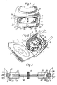
- Fig. 1 is a front view of a preferred embodiment of the pump according to the present invention,
- Fig. 2 is an elevation view of the pump in Fig. 1, having its lid in open position, and
- Fig. 3 is a schematic view of an especially preferred embodiment of the locking means for locking the tube in the pump in Figs. 1 and 2.
- As shown in Figs. 1 and 2 the pump according to the present invention may conveniently be housed in an essentially rectangular box 1 comprising a cup-
shaped bottom portion 2 and to an openable andclosable lid 3. - Preferably, said
lid 3 has acentral opening 4 which may be covered by for example a transparentplastic cover 5, whereby it is possible to supervise the pump without the need to open the lid. - Centrally located in the cup-
shaped bottom portion 2 is arotatable rotor 6 comprising for example two or more circumferentially locatedrollers 7a. 7b. Said rollers are adapted to compress thetube 8 against theinner wall 9 of the cup-shaped bottom portion to pump for example a liquid contained in the tube frominlet 10 tooutlet 11. - According to the present invention said pump comprises thus a
flexible tube 8 which is arranged in a path between saidinlet 10 and saidoutlet 11, and locking means to lock the tube at said inlet and outlet, respectively. - As suggested in Figs. 1 and 2 said means comprises two
mowable organs seat inlet 10 and saidoutlet 11, as will be described in more detail with reference to Fig. 3. - In Fig. 3 there is shown an especially preferred embodiment of said locking means for locking the tube in for example the pump as shown in Figs. 1 and 2. According to this embodiment said
slides respective end common rod 18 and being mowable towards and from, respectively, saidseats tube 8 by rotation of therod 18 by means of a centrally locatedwheel 19. - As suggested in Fig. 3 by broken lines each of said
slides seat 20, 21 for receiving of a corresponding threadedend rod 18. If, for example the oneend 16 of the rod is clockwisely threaded and theother end 17 is anticlockwisely threaded theslides - 14 and 15 for locking and releasing, respectively, the
tube 8 at theinlet 10 andoutlet 11. - From Fig. 3 it can furthermore be seen that the
respective surfaces slides tube 8, are cup-shaped, whereby each of said cup-shaped surfaces has an extendedlower edge tube 8 towards the corresponding cup-shaped sides 26 and 27 of theseat - The
rotor 6 shown in Figs. 1 and 2 is preferably rotated by means of a motor (not shown) via a drive shaft (not shown) which is received in the bottom portion of the rotor through a suitable bearing. - The pump according to the present invention is especially adapted to be used in connection with heart/lung machines, but is also suitable in other applications where it is often needed to change tube dimensions in dependency on the desired flow range,
Claims (4)
Priority Applications (1)
| Application Number | Priority Date | Filing Date | Title |
|---|---|---|---|
| AT81109187T ATE6167T1 (en) | 1980-11-06 | 1981-10-29 | PUMP WITH A LOCKING GAN FOR A HOSE. |
Applications Claiming Priority (2)
| Application Number | Priority Date | Filing Date | Title |
|---|---|---|---|
| SE8007803 | 1980-11-06 | ||
| SE8007803A SE439041B (en) | 1980-11-06 | 1980-11-06 | HOSE PUMP CONTAINING MEASURES FOR LOADING THE HOSE |
Publications (3)
| Publication Number | Publication Date |
|---|---|
| EP0051815A1 EP0051815A1 (en) | 1982-05-19 |
| EP0051815B1 EP0051815B1 (en) | 1984-02-08 |
| EP0051815B2 true EP0051815B2 (en) | 1990-02-28 |
Family
ID=20342178
Family Applications (1)
| Application Number | Title | Priority Date | Filing Date |
|---|---|---|---|
| EP81109187A Expired - Lifetime EP0051815B2 (en) | 1980-11-06 | 1981-10-29 | Pump comprising locking means for a flexible tube |
Country Status (8)
| Country | Link |
|---|---|
| US (1) | US4412793A (en) |
| EP (1) | EP0051815B2 (en) |
| JP (1) | JPS57108489A (en) |
| AT (1) | ATE6167T1 (en) |
| DE (1) | DE3162182D1 (en) |
| DK (1) | DK150945C (en) |
| IE (1) | IE52158B1 (en) |
| SE (1) | SE439041B (en) |
Families Citing this family (11)
| Publication number | Priority date | Publication date | Assignee | Title |
|---|---|---|---|---|
| US4527323A (en) * | 1983-10-11 | 1985-07-09 | Cole-Parmer Instrument Company | Tubing loading key |
| US4552516A (en) * | 1984-06-15 | 1985-11-12 | Cole-Parmer Instrument Company | Peristaltic pump |
| US4909713A (en) * | 1986-05-07 | 1990-03-20 | Cobe Laboratories, Inc. | Peristaltic pump |
| US5062775A (en) * | 1989-09-29 | 1991-11-05 | Rocky Mountain Research, Inc. | Roller pump in an extra corporeal support system |
| US5110270A (en) * | 1990-09-10 | 1992-05-05 | Morrick Joseph Q | Peristaltic pump with spring means to urge slide members and attached rollers radially outward on a rotor |
| US5190448A (en) * | 1991-07-12 | 1993-03-02 | Sherwood Medical Company | Tube placement and retention member |
| NL9500442A (en) * | 1995-03-06 | 1996-10-01 | Elu Ijmond Techniek B V | Hose pump. |
| NZ523300A (en) * | 2002-12-20 | 2005-12-23 | Impian Technologies Ltd | Peristaltic pump head and tube holder |
| ES2238897B1 (en) * | 2003-03-11 | 2006-08-01 | Institut Municipal D'assistencia Sanitaria (Imas) | PERISTALTIC PUMP FOR THE TRANSFER OF LIQUIDS. |
| JP5744319B2 (en) | 2011-05-18 | 2015-07-08 | ウルリッヒ ゲーエムベーハー ウント コー. カーゲー | Prosthetic intervertebral disc |
| US10578096B2 (en) | 2016-06-30 | 2020-03-03 | Cole-Parmer Instrument Company Llc | Peristaltic pumphead and methods for assembly thereof |
Family Cites Families (7)
| Publication number | Priority date | Publication date | Assignee | Title |
|---|---|---|---|---|
| US485484A (en) * | 1892-11-01 | Band-tightener | ||
| US3138104A (en) * | 1962-11-23 | 1964-06-23 | Manostat Corp | Variable feed pump and related method |
| US3567345A (en) * | 1969-02-10 | 1971-03-02 | Shamban & Co W S | Peristaltic pump |
| US3885894A (en) * | 1973-04-13 | 1975-05-27 | Sikes Ind Inc | Roller-type blood pump |
| DE2535650C2 (en) * | 1975-08-09 | 1982-05-27 | Dr. Eduard Fresenius, Chemisch-pharmazeutische Industrie KG Apparatebau KG, 6380 Bad Homburg | Roller peristaltic pump with an electric drive motor |
| US4025241A (en) * | 1975-12-22 | 1977-05-24 | Miles Laboratories, Inc. | Peristaltic pump with tube pinching members capable of biasing the tubing away from the pump rollers |
| US4231725A (en) * | 1978-10-16 | 1980-11-04 | Cole-Parmer Instrument Company | Peristaltic pump |
-
1980
- 1980-11-06 SE SE8007803A patent/SE439041B/en not_active IP Right Cessation
-
1981
- 1981-10-28 US US06/315,924 patent/US4412793A/en not_active Expired - Fee Related
- 1981-10-29 EP EP81109187A patent/EP0051815B2/en not_active Expired - Lifetime
- 1981-10-29 IE IE2542/81A patent/IE52158B1/en unknown
- 1981-10-29 DE DE8181109187T patent/DE3162182D1/en not_active Expired
- 1981-10-29 AT AT81109187T patent/ATE6167T1/en not_active IP Right Cessation
- 1981-11-04 DK DK487881A patent/DK150945C/en not_active IP Right Cessation
- 1981-11-06 JP JP56178239A patent/JPS57108489A/en active Pending
Also Published As
| Publication number | Publication date |
|---|---|
| ATE6167T1 (en) | 1984-02-15 |
| JPS57108489A (en) | 1982-07-06 |
| DK150945C (en) | 1988-03-28 |
| US4412793A (en) | 1983-11-01 |
| SE439041B (en) | 1985-05-28 |
| DK487881A (en) | 1982-05-07 |
| SE8007803L (en) | 1982-05-07 |
| DK150945B (en) | 1987-09-28 |
| EP0051815A1 (en) | 1982-05-19 |
| EP0051815B1 (en) | 1984-02-08 |
| IE52158B1 (en) | 1987-07-22 |
| DE3162182D1 (en) | 1984-03-15 |
| IE812542L (en) | 1982-05-06 |
Similar Documents
| Publication | Publication Date | Title |
|---|---|---|
| EP0051815B2 (en) | Pump comprising locking means for a flexible tube | |
| CA1284598C (en) | Self-loading peristaltic pump | |
| US5388568A (en) | Manipulator assembly for an endoscope | |
| DE3828122A1 (en) | HOSE PUMP CASSETTE | |
| US5201348A (en) | Evacuating apparatus for a microtitration diaphragm plate | |
| NL8002714A (en) | DEVICE FOR PROCESSING MEAT SERVINGS. | |
| AU2373788A (en) | Two chambered autotransfuser device and method of use | |
| US4436277A (en) | Torque pinch valve | |
| JPS5834717A (en) | Cooling liquid system for rotary edge cutter | |
| US5468100A (en) | Adjustable gap two-member rotary tool | |
| EP0289969A3 (en) | Apparatus for processing fluids | |
| EP0235645A3 (en) | Machine tool | |
| US4127231A (en) | Support arm for centrifugal liquid processing apparatus | |
| CA2022152A1 (en) | Device for closing the containment well of a blood centrifugation cell in a centrifugal machine | |
| DE2841906B1 (en) | Liquid ring compressor or vacuum pump | |
| FR2370191A1 (en) | VISCOUS FAN DRIVE KIT | |
| US3980251A (en) | Apparatus for changing thread spacing | |
| JPH0644619Y2 (en) | Parallel open / close chuck device | |
| US6119726A (en) | Apparatus for effecting transfer of fluid from any one of a plurality of fluid sources to a single fluid outlet | |
| GB1442308A (en) | Web or blank cutting apparatus | |
| JP2521802Y2 (en) | Parallel opening and closing chuck device | |
| JPS62246441A (en) | Movable table | |
| DE3844756C2 (en) | Cassette for peristaltic blood pump | |
| US4666424A (en) | Centrifuge door | |
| GB2230054A (en) | Rotary screw compressor control |
Legal Events
| Date | Code | Title | Description |
|---|---|---|---|
| PUAI | Public reference made under article 153(3) epc to a published international application that has entered the european phase |
Free format text: ORIGINAL CODE: 0009012 |
|
| AK | Designated contracting states |
Designated state(s): AT BE CH DE FR GB IT LI LU NL |
|
| 17P | Request for examination filed |
Effective date: 19820322 |
|
| RAP1 | Party data changed (applicant data changed or rights of an application transferred) |
Owner name: GAMBRO LUNDIA AB |
|
| ITF | It: translation for a ep patent filed | ||
| GRAA | (expected) grant |
Free format text: ORIGINAL CODE: 0009210 |
|
| AK | Designated contracting states |
Designated state(s): AT BE CH DE FR GB IT LI LU NL |
|
| REF | Corresponds to: |
Ref document number: 6167 Country of ref document: AT Date of ref document: 19840215 Kind code of ref document: T |
|
| REF | Corresponds to: |
Ref document number: 3162182 Country of ref document: DE Date of ref document: 19840315 |
|
| ET | Fr: translation filed | ||
| PG25 | Lapsed in a contracting state [announced via postgrant information from national office to epo] |
Ref country code: LU Free format text: LAPSE BECAUSE OF NON-PAYMENT OF DUE FEES Effective date: 19841031 |
|
| PLBI | Opposition filed |
Free format text: ORIGINAL CODE: 0009260 |
|
| PGFP | Annual fee paid to national office [announced via postgrant information from national office to epo] |
Ref country code: BE Payment date: 19841231 Year of fee payment: 4 |
|
| 26 | Opposition filed |
Opponent name: FRESENIUS AG Effective date: 19841108 |
|
| NLR1 | Nl: opposition has been filed with the epo |
Opponent name: FRESENIUS AG. |
|
| PLAB | Opposition data, opponent's data or that of the opponent's representative modified |
Free format text: ORIGINAL CODE: 0009299OPPO |
|
| R26 | Opposition filed (corrected) |
Opponent name: FRESENIUS AG Effective date: 19841108 |
|
| PGFP | Annual fee paid to national office [announced via postgrant information from national office to epo] |
Ref country code: AT Payment date: 19861022 Year of fee payment: 6 |
|
| PGFP | Annual fee paid to national office [announced via postgrant information from national office to epo] |
Ref country code: NL Payment date: 19871031 Year of fee payment: 7 |
|
| PG25 | Lapsed in a contracting state [announced via postgrant information from national office to epo] |
Ref country code: AT Effective date: 19881029 |
|
| PG25 | Lapsed in a contracting state [announced via postgrant information from national office to epo] |
Ref country code: LI Effective date: 19881031 Ref country code: CH Effective date: 19881031 Ref country code: BE Effective date: 19881031 |
|
| BERE | Be: lapsed |
Owner name: GAMBRO LUNDIA A.B. Effective date: 19881031 |
|
| PG25 | Lapsed in a contracting state [announced via postgrant information from national office to epo] |
Ref country code: NL Effective date: 19890501 |
|
| NLV4 | Nl: lapsed or anulled due to non-payment of the annual fee | ||
| REG | Reference to a national code |
Ref country code: CH Ref legal event code: PL |
|
| PUAH | Patent maintained in amended form |
Free format text: ORIGINAL CODE: 0009272 |
|
| STAA | Information on the status of an ep patent application or granted ep patent |
Free format text: STATUS: PATENT MAINTAINED AS AMENDED |
|
| 27A | Patent maintained in amended form |
Effective date: 19900228 |
|
| AK | Designated contracting states |
Kind code of ref document: B2 Designated state(s): AT BE CH DE FR GB IT LI LU NL |
|
| ITF | It: translation for a ep patent filed | ||
| ET3 | Fr: translation filed ** decision concerning opposition | ||
| PGFP | Annual fee paid to national office [announced via postgrant information from national office to epo] |
Ref country code: FR Payment date: 19900928 Year of fee payment: 10 |
|
| PGFP | Annual fee paid to national office [announced via postgrant information from national office to epo] |
Ref country code: GB Payment date: 19901023 Year of fee payment: 10 |
|
| ITTA | It: last paid annual fee | ||
| PG25 | Lapsed in a contracting state [announced via postgrant information from national office to epo] |
Ref country code: GB Effective date: 19911029 |
|
| GBPC | Gb: european patent ceased through non-payment of renewal fee | ||
| PG25 | Lapsed in a contracting state [announced via postgrant information from national office to epo] |
Ref country code: FR Effective date: 19920630 |
|
| REG | Reference to a national code |
Ref country code: FR Ref legal event code: ST |
|
| PGFP | Annual fee paid to national office [announced via postgrant information from national office to epo] |
Ref country code: DE Payment date: 19931124 Year of fee payment: 13 |
|
| PG25 | Lapsed in a contracting state [announced via postgrant information from national office to epo] |
Ref country code: DE Effective date: 19950701 |
|
| APAC | Appeal dossier modified |
Free format text: ORIGINAL CODE: EPIDOS NOAPO |
|
| APAC | Appeal dossier modified |
Free format text: ORIGINAL CODE: EPIDOS NOAPO |
|
| APAH | Appeal reference modified |
Free format text: ORIGINAL CODE: EPIDOSCREFNO |