EP0051820A1 - Schaltung zur schnellen Ableitung einer Restladung auf einem zur Überwachung hoher Wechselspannungen verwendeten kapazitiven Spannungsteiler - Google Patents
Schaltung zur schnellen Ableitung einer Restladung auf einem zur Überwachung hoher Wechselspannungen verwendeten kapazitiven Spannungsteiler Download PDFInfo
- Publication number
- EP0051820A1 EP0051820A1 EP81109205A EP81109205A EP0051820A1 EP 0051820 A1 EP0051820 A1 EP 0051820A1 EP 81109205 A EP81109205 A EP 81109205A EP 81109205 A EP81109205 A EP 81109205A EP 0051820 A1 EP0051820 A1 EP 0051820A1
- Authority
- EP
- European Patent Office
- Prior art keywords
- voltage
- bridge
- windings
- parallel
- controlled
- Prior art date
- Legal status (The legal status is an assumption and is not a legal conclusion. Google has not performed a legal analysis and makes no representation as to the accuracy of the status listed.)
- Granted
Links
Images
Classifications
-
- G—PHYSICS
- G01—MEASURING; TESTING
- G01R—MEASURING ELECTRIC VARIABLES; MEASURING MAGNETIC VARIABLES
- G01R15/00—Details of measuring arrangements of the types provided for in groups G01R17/00 - G01R29/00, G01R33/00 - G01R33/26 or G01R35/00
- G01R15/04—Voltage dividers
- G01R15/06—Voltage dividers having reactive components, e.g. capacitive transformer
Definitions
- the present invention relates to the monitoring of high alternating voltages, in particular those of high voltage electric power lines.
- this error voltage saturates the monitoring equipment receiving the measurement signal and makes it inoperative. It is known to protect monitoring equipment by inserting between it and the capacitive divider a selective filter centered on the frequency of the high voltage that, whenever trapped charges are likely to appear, that is to say for a considerable time at the start of certain power-ups. However, this filter has the drawback of also filtering the measurement signal and making it imprecise for the few hundred seconds it is inserted.
- the present invention aims to limit the drawbacks due to trapped charges by allowing them to be eliminated very quickly without disturbing the measurement signal too much.
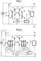
- the device according to the invention is advantageously supplemented by a controlled switch inserted in series with the rectifier bridge at the terminals of the basic capacity, closed after a cut in the high voltage for more than a few seconds and opened shortly after the restoration of the high voltage, said controlled switch being controlled by a timer circuit excited by an alternating voltage detector connected to the terminals of the basic capacity.
- the controlled switch 19 is not compulsory and can be replaced by a shunt. It makes it possible to connect the rectifier bridge and its windings only when the trapped charges are likely to appear and for the duration of their elimination.
- the device comprises two branches of similar structures, with the exception of the direction of the diodes, joined by the controlled switch 19 in parallel on the terminals 13, 14 of the base capacity 10, one consisting of the elements 16, 18, 20, 22 ensuring the flow of the trapped charges tending to make the terminal 13 of the base capacitor 10 positive with respect to its terminal 14 and the other consisting of the elements 15, 17, 21, 23 ensuring the flow of the trapped charges tending to make terminal 13 of base capacitor 10 negative with respect to its terminal 14.
- the disturbance brought to the measurement signal by the device depends on the current which it draws in steady state at the basic capacity 10 when the controlled switch 19 is closed. To appreciate it, one can calculate the current passing through one of the inductances 20 or 21 of the device when it is subjected to an AC voltage. We are interested for example in the inductance 20 and it is supposed that the terminal 13 of the basic capacitor 10 is carried, compared to the terminal 14 with an alternating potential V sin wt
- the current in the inductor 20 has the same value at the end of a period of forced excitation or at the start of a period of free damping, which makes it possible to write: and therefore to completely determine the current passing through the inductor 20 during the periods of forced excitation.
- This current is that derived from the voltage source V sin wt by the device during the time intervals (0, ⁇ / w) to within 2 K ⁇ because during these moments the diode 17 in series in the other branch is blocked.
- This current can be broken down into two parts, the first part: which is the current derived from the voltage source by an inductor of value L in series with a resistance of value R, and a second part: which is a pulsating current.
- the current component i B in the measurement where it comes close to the value: at the start of the positive half-waves of the alternating voltage V sin wt, that is to say where: and insofar as it becomes negligible after half a half-cycle can be considered as a corrective component, present during the first half of the positive half-vibrations of the voltage source V sin wt, tending to counteract the effect of the phase shift of the current component i A. Under these conditions it can be neglected for the study of disturbances to the measurement signal brought by the device in steady state.
- the assimilation, in steady state of the device to an inductance in series with a resistance, having a high impedance compared to the basic capacity is therefore justified.
- a relative amplitude error of the order of 9% and a phase error of the order of 3 degrees is obtained on the measurement signal.
- the trapped charges are elapsed in a duration of 86 ms whereas, without the device they would need about twenty seconds, duration which is that of the discharge time constant with a capacity of 10 ⁇ F in a resistance of 2M ⁇ .
- FIG. 2 illustrates a device comprising an auxiliary winding in parallel on each winding.
- This device takes up the structure of that of FIG. 1, the elements unchanged between the two figures having the same indexing.
- Each auxiliary winding is represented by an inductor 24 respectively 25 in series with a resistor 26 respectively 27. They are each connected in parallel with a damping diode 28 respectively 29 and in series with a controlled switch 33 respectively 34 controlled by a timer circuit 32 slightly different from that 31 in FIG. 1.
- the timer circuit 32 is excited by the AC voltage detector circuit 30. It has a triple delay, the first allowing a closing order to be transmitted to the controlled switches 19, 33 and 34 only after detection of a cut in the high alternating voltage greater in duration than a few seconds, for example five, the second transmitting an opening order to the controlled switches 33 and 34 only a few tens of milliseconds after the detection of the re-establishment of the high alternating voltage and the third transmitting a order to open the controlled switch 19 only a hundred milliseconds after the detection of the re-establishment of the high alternating voltage.
- auxiliary windings placed in parallel on the windings and gradually disconnected when the high alternating voltage is restored makes it possible to reconcile the requirement of a low inductance value necessary for the rapid flow of trapped loads and that of a high inductance value necessary to reduce the disturbances brought by the device to the measurement signal.
- the measurement signal being disturbed in any case during the flow of the trapped charges, it is possible to admit, during this flow, a large percentage of error.
- the device shown in the figure cannot simply be used. with low inductance windings because the disturbances it brings to the measurement signal cause when it is disconnected by the opening of the controlled switch 19, the appearance of new trapped charges generating a voltage jump in the measurement signal can have the same relative amplitude as the voltage error due to the device itself.
Landscapes
- Engineering & Computer Science (AREA)
- Power Engineering (AREA)
- Physics & Mathematics (AREA)
- General Physics & Mathematics (AREA)
- Rectifiers (AREA)
- Measurement Of Current Or Voltage (AREA)
- Measuring Instrument Details And Bridges, And Automatic Balancing Devices (AREA)
Applications Claiming Priority (2)
| Application Number | Priority Date | Filing Date | Title |
|---|---|---|---|
| FR8023700 | 1980-11-06 | ||
| FR8023700A FR2493527A1 (fr) | 1980-11-06 | 1980-11-06 | Dispositif pour l'elimination rapide des charges piegees dans un pont diviseur capacitif utilise pour la surveillance des tensions alternatives elevees |
Publications (2)
| Publication Number | Publication Date |
|---|---|
| EP0051820A1 true EP0051820A1 (de) | 1982-05-19 |
| EP0051820B1 EP0051820B1 (de) | 1985-04-03 |
Family
ID=9247733
Family Applications (1)
| Application Number | Title | Priority Date | Filing Date |
|---|---|---|---|
| EP81109205A Expired EP0051820B1 (de) | 1980-11-06 | 1981-10-29 | Schaltung zur schnellen Ableitung einer Restladung auf einem zur Überwachung hoher Wechselspannungen verwendeten kapazitiven Spannungsteiler |
Country Status (8)
| Country | Link |
|---|---|
| US (1) | US4437134A (de) |
| EP (1) | EP0051820B1 (de) |
| JP (1) | JPS57108669A (de) |
| BR (1) | BR8107191A (de) |
| CA (1) | CA1167096A (de) |
| DE (1) | DE3169726D1 (de) |
| FR (1) | FR2493527A1 (de) |
| IN (1) | IN157270B (de) |
Families Citing this family (17)
| Publication number | Priority date | Publication date | Assignee | Title |
|---|---|---|---|---|
| FR2583590B1 (fr) * | 1985-06-12 | 1987-08-07 | Cables De Lyon Geoffroy Delore | Dispositif de protection d'une ligne electrique d'energie contre les surtensions transitoires elevees |
| DE3634855C1 (de) * | 1986-10-13 | 1988-03-31 | Peter Seitz | Kapazitive Messanordnung zur Bestimmung von Kraeften und/oder Druecken |
| US4999730A (en) * | 1989-05-10 | 1991-03-12 | Pickard Harold W | Line voltage monitor and controller |
| US5907251A (en) * | 1996-11-22 | 1999-05-25 | International Business Machines Corp. | Low voltage swing capacitive bus driver device |
| DE19916686A1 (de) * | 1999-04-14 | 2000-10-19 | Moeller Gmbh | Eingangsschaltung für relativ hochstromige zu überwachende AC-Signale |
| US6518814B1 (en) * | 1999-12-28 | 2003-02-11 | Koninklijke Philips Electronics N.V. | High-voltage capacitor voltage divider circuit having a high-voltage silicon-on-insulation (SOI) capacitor |
| EP1264191B1 (de) * | 2000-03-14 | 2005-07-06 | HSP Hochspannungsgeräte Porz GmbH | Vorrichtung und verfahren zur überwachung einer kondensatordurchführung |
| US6420875B1 (en) | 2000-03-22 | 2002-07-16 | General Electric Company | CVT transient filter |
| US6341493B1 (en) * | 2000-07-19 | 2002-01-29 | American Standard International Inc. | HVAC control and method for interpreting broad range of input voltages |
| DE102006020086A1 (de) * | 2006-04-25 | 2007-10-31 | Siemens Ag | Verfahren und Vorrichtung zur Prüfung von Stromwandlern mittels Hochstromimpuls |
| US7808219B2 (en) * | 2007-11-26 | 2010-10-05 | Honeywell International Inc. | Method and apparatus of capacitor divider based offline AC-DC converter |
| US8270188B1 (en) * | 2011-10-03 | 2012-09-18 | Google Inc. | Apparatus and methodology for generating an auxiliary low power output by using three-phase input power |
| US8903675B2 (en) * | 2011-10-14 | 2014-12-02 | Vibrant Corporation | Acoustic systems and methods for nondestructive testing of a part through frequency sweeps |
| RU2527658C1 (ru) * | 2013-01-15 | 2014-09-10 | Федеральное государственное бюджетное образовательное учреждение высшего профессионального образования "Юго-Западный государственный университет" (ЮЗГУ) | Мостовой измеритель параметров двухполюсников |
| JP6611530B2 (ja) * | 2015-09-11 | 2019-11-27 | キヤノン株式会社 | 電力供給装置及び画像形成装置 |
| CN108802658B (zh) * | 2017-04-26 | 2021-07-23 | 西门子公司 | 检测电容型电压互感器中残压状态的装置和方法 |
| CN109031180B (zh) * | 2018-07-26 | 2020-08-11 | 西门子电力自动化有限公司 | 检测电容式电压互感器的残压状态的方法与装置 |
Family Cites Families (4)
| Publication number | Priority date | Publication date | Assignee | Title |
|---|---|---|---|---|
| DE2634595A1 (de) * | 1975-08-05 | 1977-03-03 | Gen Electric | Geraet zur ueberwachung hoher wechselspannungen |
| GB1585488A (en) | 1977-05-11 | 1981-03-04 | Gen Electric | Apparatus for monitoring high alternating voltages |
| NL179684C (nl) * | 1977-10-24 | 1986-10-16 | Hazemeijer Bv | Capacitieve wisselspanningsdeler. |
| FR2456327A1 (fr) | 1979-05-09 | 1980-12-05 | Enertec | Perfectionnement aux transformateurs capacitifs de tension a sortie electronique |
-
1980
- 1980-11-06 FR FR8023700A patent/FR2493527A1/fr active Granted
-
1981
- 1981-10-29 EP EP81109205A patent/EP0051820B1/de not_active Expired
- 1981-10-29 DE DE8181109205T patent/DE3169726D1/de not_active Expired
- 1981-11-03 IN IN697/DEL/81A patent/IN157270B/en unknown
- 1981-11-05 JP JP56177771A patent/JPS57108669A/ja active Pending
- 1981-11-05 BR BR8107191A patent/BR8107191A/pt unknown
- 1981-11-05 US US06/318,535 patent/US4437134A/en not_active Expired - Fee Related
- 1981-11-05 CA CA000389473A patent/CA1167096A/fr not_active Expired
Also Published As
| Publication number | Publication date |
|---|---|
| JPS57108669A (en) | 1982-07-06 |
| US4437134A (en) | 1984-03-13 |
| BR8107191A (pt) | 1982-07-27 |
| IN157270B (de) | 1986-02-22 |
| EP0051820B1 (de) | 1985-04-03 |
| FR2493527A1 (fr) | 1982-05-07 |
| CA1167096A (fr) | 1984-05-08 |
| FR2493527B1 (de) | 1982-11-26 |
| DE3169726D1 (en) | 1985-05-09 |
Similar Documents
| Publication | Publication Date | Title |
|---|---|---|
| EP0051820B1 (de) | Schaltung zur schnellen Ableitung einer Restladung auf einem zur Überwachung hoher Wechselspannungen verwendeten kapazitiven Spannungsteiler | |
| EP0019507B1 (de) | Verbesserung kapazitiver Spannungstransformatoren mit elektronischem Ausgang | |
| FR2577728A1 (fr) | Dispositif d'alimentation en energie stabilisee | |
| FR2863115A1 (fr) | Interrupteur de circuit en cas de defaut a la terre. | |
| FR2587155A1 (fr) | Circuit de commande pour des transistors mos de puissance a canal n montes dans des etages push-pull | |
| EP0836280B1 (de) | Elektronischer Schalter mit Zweidraht-Versorgung | |
| EP0060790A1 (de) | Fehlerstromempfindliche Ausschalter | |
| EP4216386A1 (de) | Schutzvorrichtung für eine elektrische anlage in wechselstrom und/oder gleichstrom | |
| FR2609552A1 (fr) | Circuit de mesure de la composante continue du courant parcourant l'enroulement primaire du transformateur de sortie d'un onduleur | |
| EP0200656A1 (de) | Unterbrechungsfreie Wechselstromversorgung mit einer Kraft von 1500 VA oder weniger | |
| EP0075357B1 (de) | Speiseschaltung einer mehrphasigen elektrischen Asynchronmaschine | |
| EP0116482B1 (de) | Spannungsregler mit Phasenspannungserhaltung und Erregungskurzschlussschutz für einen Wechselstromgenerator | |
| FR2539913A1 (fr) | Montage de commande electronique destine a produire un comportement de commutation monostable avec un relais bistable | |
| EP0285532B1 (de) | Fehlerdetektor für ein dreiphasiges Netz, das Lasten mit Vollwellzügen speist | |
| EP0555144A1 (de) | Pumpstation | |
| EP0025404B1 (de) | Kurzschlusselement für Serienschaltung | |
| FR2570562A1 (fr) | Commutateur electronique | |
| WO1994003954A1 (fr) | Dispositif de detection de defauts sur un reseau de distribution d'energie electrique souterrain | |
| EP2253183B1 (de) | Elektrisierer für einen elektrozaun | |
| FR1317824A (de) | ||
| EP0601593A2 (de) | Stromvervielfacher-Versorgungsvorrichtung | |
| EP3815227A1 (de) | Vorrichtung zum schutz einer leistungskomponente für eine transistorbrücke | |
| BE654061A (fr) | Relais voltmétrique à temps dépendant | |
| BE540388A (de) | ||
| BE662938A (fr) | Relais détecteur de courts-circuits sur des lignes de traction à courant continu |
Legal Events
| Date | Code | Title | Description |
|---|---|---|---|
| PUAI | Public reference made under article 153(3) epc to a published international application that has entered the european phase |
Free format text: ORIGINAL CODE: 0009012 |
|
| AK | Designated contracting states |
Designated state(s): BE CH DE FR SE |
|
| 17P | Request for examination filed |
Effective date: 19820812 |
|
| GRAA | (expected) grant |
Free format text: ORIGINAL CODE: 0009210 |
|
| AK | Designated contracting states |
Designated state(s): BE CH DE FR LI SE |
|
| REF | Corresponds to: |
Ref document number: 3169726 Country of ref document: DE Date of ref document: 19850509 |
|
| PLBE | No opposition filed within time limit |
Free format text: ORIGINAL CODE: 0009261 |
|
| STAA | Information on the status of an ep patent application or granted ep patent |
Free format text: STATUS: NO OPPOSITION FILED WITHIN TIME LIMIT |
|
| 26N | No opposition filed | ||
| PG25 | Lapsed in a contracting state [announced via postgrant information from national office to epo] |
Ref country code: SE Effective date: 19871030 |
|
| PG25 | Lapsed in a contracting state [announced via postgrant information from national office to epo] |
Ref country code: LI Effective date: 19871031 Ref country code: CH Effective date: 19871031 Ref country code: BE Effective date: 19871031 |
|
| BERE | Be: lapsed |
Owner name: ALSTHOM-ATLANTIQUE Effective date: 19871031 |
|
| PG25 | Lapsed in a contracting state [announced via postgrant information from national office to epo] |
Ref country code: FR Free format text: LAPSE BECAUSE OF NON-PAYMENT OF DUE FEES Effective date: 19880630 |
|
| REG | Reference to a national code |
Ref country code: CH Ref legal event code: PL |
|
| PG25 | Lapsed in a contracting state [announced via postgrant information from national office to epo] |
Ref country code: DE Effective date: 19880701 |
|
| REG | Reference to a national code |
Ref country code: FR Ref legal event code: ST |
|
| EUG | Se: european patent has lapsed |
Ref document number: 81109205.5 Effective date: 19880707 |