EP0051844A2 - Floor for a broiler house - Google Patents
Floor for a broiler house Download PDFInfo
- Publication number
- EP0051844A2 EP0051844A2 EP81109465A EP81109465A EP0051844A2 EP 0051844 A2 EP0051844 A2 EP 0051844A2 EP 81109465 A EP81109465 A EP 81109465A EP 81109465 A EP81109465 A EP 81109465A EP 0051844 A2 EP0051844 A2 EP 0051844A2
- Authority
- EP
- European Patent Office
- Prior art keywords
- support
- profile
- mats
- profiles
- floor
- Prior art date
- Legal status (The legal status is an assumption and is not a legal conclusion. Google has not performed a legal analysis and makes no representation as to the accuracy of the status listed.)
- Granted
Links
Images




Classifications
-
- A—HUMAN NECESSITIES
- A01—AGRICULTURE; FORESTRY; ANIMAL HUSBANDRY; HUNTING; TRAPPING; FISHING
- A01K—ANIMAL HUSBANDRY; AVICULTURE; APICULTURE; PISCICULTURE; FISHING; REARING OR BREEDING ANIMALS, NOT OTHERWISE PROVIDED FOR; NEW BREEDS OF ANIMALS
- A01K31/00—Housing birds
- A01K31/002—Poultry cages, e.g. transport boxes
- A01K31/007—Floors
-
- A—HUMAN NECESSITIES
- A01—AGRICULTURE; FORESTRY; ANIMAL HUSBANDRY; HUNTING; TRAPPING; FISHING
- A01K—ANIMAL HUSBANDRY; AVICULTURE; APICULTURE; PISCICULTURE; FISHING; REARING OR BREEDING ANIMALS, NOT OTHERWISE PROVIDED FOR; NEW BREEDS OF ANIMALS
- A01K31/00—Housing birds
- A01K31/22—Poultry runs ; Poultry houses, including auxiliary features, e.g. feeding, watering, demanuring
Definitions
- the invention relates to a device for keeping small animals, in particular fattening poultry, such as chickens, in a barn with a continuous, grid-shaped bottom designed as a conveyor.
- a grid-shaped support has already been proposed above the barn floor provide floor that is designed like a conveyor belt.
- the supporting floor which consists of individual, side-by-side tracks, is moved to one side of the barn, taking the chickens with it.
- the chickens are transported on a transversely directed conveyor belt for removal from the barn (DE-A-27 03 968).
- the supporting floor or the tracks of the same consist of individual, articulated, interconnected plastic bars. These are rotatably arranged with bearing sleeves on transverse support rods.
- Such a design of the supporting floor or the tracks of the same has proven to be unfavorable in practice.
- the pad is too hard for the sensitive animals.
- the ribs create pressure points, especially in the area of the animals' breasts, when they rest on the supporting floor for a long time.
- the relative movement between the grid elements or bars is unfavorable because of the risk of contamination, feces and the like. the like
- the invention has for its object to further develop and improve a device of the type mentioned in such a way that the disadvantages of previously known systems are eliminated.
- it is a matter of creating a supporting floor that takes the biological peculiarities of small animals (chickens) into account.
- the device according to the invention is characterized in that the base consists of intersecting support profiles made of elastic, soft material, in particular of soft PVC.
- the supporting floor therefore no longer consists of links that can be moved relative to one another, but instead of a continuous grid or network of joints without joints connected, intersecting support profiles.
- the special selection of the material - in particular soft PVC - on the one hand brings about an elasticity of the support base or the webs formed therefrom such that they can be deflected like conveyor belts.
- this creates an animal-friendly storage area that is equipped with a soft surface of the support elements (support profiles).
- the support profiles of the latticework which are preferably produced using the immersion process, have a very smooth, easily deformable surface, which enables the animals to both move and rest on the support floor without stress.
- the support profiles are designed according to the invention as an elongated hollow body, in particular with an approximately U-shaped cross section, a rounded, arch-shaped web of this profile pointing upwards and serving as a bearing surface, while the legs of this profile point downward.
- the supporting floor is provided with elevations projecting above the floor level, in particular ribs, beads and the like. Like. provided. These are also made of soft, elastic material, are designed with a rounded surface and form animal-friendly support and seating surfaces, which primarily ensure that the sensitive breast areas are not exposed to such stresses during rest on such elevations.
- the individual webs consist of one-piece or one-piece mats.
- Several mats are connected to each other in the conveying or longitudinal direction of a web to form the same and are connected to one another without gaps. bound, preferably by a clamp connection, which forms a top cover profile with bulge-like increase.
- the support floor according to the invention can be loaded and walked on (by personnel).
- Reinforcements are embedded in the support profiles to increase the load capacity.
- These are preferably support rods directed transversely to the tracks, with which the tracks are supported on lateral support members.
- the conveyor drive of the webs is exerted on the support rods, preferably by connecting the support rods to lateral traction elements (transport chains).
- elevations are formed above the supporting rods, preferably in the form of continuous hollow bodies.
- the mat also appears soft and flexible in the area of these support rods.
- a barn is shown in schematic cross section for receiving, for example, broiler chickens.
- a support floor 21 is arranged within the house above and at a distance from a house floor 20. This forms the running or standing area for the animals.
- a system of tubes 22 for the supply of feeders 23 is provided above the support base 21.
- separate drinking devices 24 also extend above the supporting base 21.
- the supporting floor 21 is designed as a conveyor for the animals and can be moved over the full width of the stables.
- the support base 21 is divided into individual tracks 25a, 25b, 25c. This who which expediently moves together and simultaneously in the conveying direction (arrow 26 in FIG. 2).
- the animals are fed to the cross conveyor 27 by the corresponding movement of the support base 21 and placed on the latter.
- the cross conveyor 27 is driven by a motor 28 across the support floor 21.
- the animals are removed, for example, through an opening 29 in the stable wall.
- the flexible or deformable webs 25a, 25b .. run at the ends over deflection rollers. 2 shows the deflecting roller 30 facing the cross conveyor 27, which is also the driving roller for the webs 25a, 25b.
- the deflecting roller 30 is driven by a motor 31.
- the tracks 25a, 25b .. are designed in a special way. These consist of individual interconnected mats 32 which form a continuous path. These in turn form the continuous support floor 21 lying side by side.
- the mats 32 essentially consist of a mesh or latticework made of longitudinal and transverse support profiles 33 made of soft, highly elastic material, in particular PVC.
- the interconnected support profiles 33 in the present case leave square lattice openings 34, the size of which is adapted to the natural characteristics of the animals. Dimensions have proven to be favorable as follows: the support profiles 33 have a width of 13 mm. The free edge length of the grid openings 34 is 18.75 mm. This results in an axial distance between the support profiles 33 of 31.75 mm. The height of a support profile 33 is 16 mm.
- the length of one Mat 32 in the longitudinal direction of the web 25a, 25b .. here is 394 mm, while the width and thus the width of the web is provided at 1918 mm.
- the support profiles 33 have a U-shaped cross section with an upward-facing arc-shaped or semicircular web 35 and legs 36 and 37 directed downward.
- the support profiles 33 are accordingly open at the bottom.
- the seat or lying surface on the support profiles 33 is rounded and the selection of the material makes it soft and smooth.
- the wall thickness of the support profiles can be 2 mm.
- stiffening or support members are incorporated into the mats 32.
- transverse support rods 38 are formed into the mats 32 at intervals from one another.
- the support rods 38 extend in the lower cross-sectional area of the mat 32 in a circular profile 39 in the present case.
- the exemplary embodiment shown is equipped with three such support rods 38 within the mat 32.
- soft, elastically flexible covers are provided above the support rods 38, specifically in the form of continuous hollow bodies 40 made of the material of the mat 32.
- the hollow bodies 40 formed with a circular cross section extend approximately with half the cross-section above the plane of the mat 32, thereby forming a bead-like elevation running across the mat 32. This serves the animals to sit on or support.
- the mats 32 of a web 25a, 25b .. are connected to one another largely without joints in the longitudinal direction thereof, specifically over the entire width of the web.
- special mat couplings are provided (Fig. 7), which consist of two clamping profiles.
- a lower profile 41 with suitable clamping legs 42 enters from below into a support profile 33a at the edge of the mats 32 to be connected to one another.
- the cross section of the support profile 33a is largely filled by the clamping leg 42, specifically by an upper support arch 43 and by a tubular profile 44 extending in the lower region.
- an upper profile 45 is inserted into the channel-shaped lower profile 41, namely pressed in, which engages with the lower profile 41 by clamping the supporting profiles 33a.
- Continuous lugs 46 arranged on the side of the upper profile 45 enter the region between the support bend 43 and the tubular profile 44 of the clamping legs 42, namely by pressing in and deforming the facing legs 36 and 37 of the supporting profiles 33a. Due to the relatively rigid lower profiles 41 and upper profiles 45, a continuous, resilient connection is created over the full width of the web 25a, 25b. This connection is easy to manufacture and can be released again on the spot.
- the upper profile 45 or the supporting part of the same is widened upward in a shell-like manner.
- a soft, highly elastic filling material, in particular foam 47, is inserted into the open cavity formed in this way. This protrudes upwards over the upper profile 45 and over the level of the mat 32 and forms an elastic, soft bead 48.
- This acts as a soft, flexible covering of the otherwise rigid mat coupling and at the same time as an increase for sitting on or resting on the animals.
- the tracks 25a, 25b .. are supported in lateral guides, namely in U-shaped support rails 49, 50.
- the upper support rails 49 serve to accommodate an upper run and the lower support rails 50 serve to accommodate a lower run of an endless conveyor chain 51.
- the support rails 49, 50 are arranged on either side of upright support supports 52 arranged centrally between adjacent tracks 25a, 25b.
- the upper support rails 49 are flush with the support supports 52.
- the webs 25a, 25b .. or mats 32 are connected to the conveyor chains 51 with the support rods 38 already described.
- the ends of the support rods 38 enter the hollow bolts of the chains 51 so that there is a direct connection to them.
- tubular profiles 44 of the clamping legs 42 of the lower profile 41 are also each provided with continuous support rods 38.
- the support supports 52 are connected to one another by cross members 53, which are designed here as flat profiles.
- Longitudinal supports 54 which are designed here as tubes, extend between the transverse supports 53 which are arranged at a distance in the longitudinal direction of the tracks 25a, 25b.
- a plurality of such longitudinal supports 54 are arranged next to one another within a path 25a, 25b.
- the longitudinal supports 54 are mounted in recesses in the cross members 53 in the upper region thereof.
- the longitudinal supports 54 fulfill a multiple function: on the one hand they serve to stiffen the structure for. the sheets 25a, 25b ..; on the other hand, they serve as supports for the mats 32, so that they cannot sag excessively. Finally, they can be used as hollow bodies (pipes) trained longitudinal supports 54 are used as continuous heating elements by passing a heating medium, in particular heated water, through the interconnected longitudinal supports 54. By means of this heating arranged below the supporting floor 21, it is possible to ensure an optimal temperature control of the barn directly in the area of the animals' stay.
- the heater can also be designed in a different way and arranged below the support base 21.
- the structure and mode of operation of the support base 21 designed as described are such that it is designed only as an upper run. Accordingly, there are no tracks 25a, 25b ... in the area of the lower run of the conveyor chain 51. If these are set in motion to remove the animals, a transverse grille 55 arranged at the end of the support floor 21 is also conveyed. This prevents the animals from jumping off over the free rear edge of the support base 21.
- FIG. 11 shows an alternative to the (releasable) clamping connection between adjacent mats 32 according to FIG. 7 in a cross section.
- the edge-side legs 36 and 37 of the adjacent mats 32 are received here in a hollow profile open at the top in the form of a U-rail 56.
- This is preferably made of rigid, resilient material, in particular metal.
- the U-rail 56 thereby has a carrying and supporting function for the web in the area of the mat connection.
- Upright profile legs 57 and 58 are shaped inwards and thereby form an undercut for the clamped legs 36, 37.
- a clamping profile 59 made of pressure-resistant material, ins, is used to fix the legs 36, 37 in the U-rail 56 special hard PVC.
- the clamping profile 59 is pressed into the U-rail 56 in a fitting or form-fitting manner by means of a clamping piece 60, specifically with the legs 36, 37 being fixed to the lateral profile legs 57, 58.
- a transverse flange 61 extending outside the U-rail 56 lies on it the top of the mats 32.
- the transverse flange 61 is, however, padded upwards, namely by a bulging bulge 62 which, as in the present case, creates an air-filled cavity with sufficient cushioning effect, but alternatively can also be filled with foam in the sense of the exemplary embodiment according to FIG. 7.
- the clamp connection enables easy, problem-free assembly of the support base 21 by connecting mats 32 to one another.
Landscapes
- Life Sciences & Earth Sciences (AREA)
- Environmental Sciences (AREA)
- Birds (AREA)
- Zoology (AREA)
- Animal Husbandry (AREA)
- Biodiversity & Conservation Biology (AREA)
- Housing For Livestock And Birds (AREA)
- Belt Conveyors (AREA)
Abstract
Bei der Aufzucht von Mastgeflügel, insbesondere Hähnchen, ist die Ausbildung des Stall- bzw. Standbodens ein besonderes Problem. Zur Vermeidung von Druckstellen und Blasen im Bereich des Brustbeins der Tiere besteht der Standboden aus sich kreuzenden Tragprofilen (13) aus elastischem, weichem Material, insbesondere Weich-PVC. Mehrere miteinander verbundene und durch querlaufende Tragstäbe abgestützte Matten bilden Bahnen und diese wiederum einen durchgehenden Stand- bzw. Stallboden. Die Bahnen können wie Transportbänder bewegt werden, um das Entstallen der Tiere zu ermöglichen.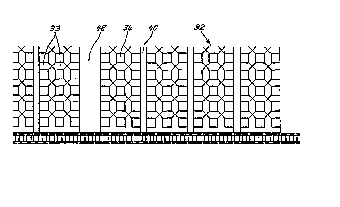
Description
Die Erfindung betrifft eine Einrichtung für die Haltung von Kleintieren, insbesondere Mastgeflügel, wie Hähnchen, in einer Stallung mit einem durchgehenden, als Förderer ausgebildeten, gitterförmigen Boden.The invention relates to a device for keeping small animals, in particular fattening poultry, such as chickens, in a barn with a continuous, grid-shaped bottom designed as a conveyor.
Die Aufzucht von Mastgeflügel, insbesondere Hähnchen, findet in großflächigen Stallungen auf einem durchgehenden Stallboden statt. Die in einer Stallung aufgezogenen Hähnchen werden gleichzeitig abtransportiert, wenn sie das erwünschte Gewicht erreicht haben.Rearing poultry, especially chickens, takes place in large stables on a continuous floor. The chickens raised in a barn are removed at the same time when they have reached the desired weight.
Um die bei dieser Kleintierhaltung problematische Entstallung zu erleichtern, ist bereits vorgeschlagen worden, oberhalb des Stallbodens einen gitterförmigen Tragboden vorzusehen, der wie ein Transportband ausgebildet ist. Der aus einzelnen, nebeneinanderliegenden Bahnen bestehende Tragboden wird unter Mitnahme der Hähnchen zu einer Seite der Stallung bewegt. Im Bereich einer Umlenkung des Tragbodens gelangen die Hähnchen auf ein quergerichtetes Transportband zum Abfördern aus der Stallung (DE-A-27 03 968).In order to facilitate the unloading problematic with this small animal husbandry, a grid-shaped support has already been proposed above the barn floor provide floor that is designed like a conveyor belt. The supporting floor, which consists of individual, side-by-side tracks, is moved to one side of the barn, taking the chickens with it. In the area of a deflection of the supporting floor, the chickens are transported on a transversely directed conveyor belt for removal from the barn (DE-A-27 03 968).
Der Tragboden bzw. die Bahnen desselben bestehen bei diesem bekannten Vorschlag aus einzelnen, gelenkig miteinander verbundenen Gitterstäben aus Kunststoff. Diese sind drehbar mit Lagerhülsen auf quergerichteten Tragstäben angeordnet. Eine derartige Ausbildung des Tragbodens bzw. der Bahnen desselben hat sich in der Praxis als ungünstig erwiesen. Die Auflage ist zu hart für die empfindlichen Tiere. Durch die Rippen entstehen Druckstellen, insbesondere im Bereich der Brust der Tiere, wenn diese längere Zeit auf dem Tragboden ruhen. Darüber hinaus ist die Relativbewegung zwischen den Gitterelementen bzw. -stäben ungünstig wegen der Gefahr von Verschmutzungen, Kotfestsetzungen u. dgl.In this known proposal, the supporting floor or the tracks of the same consist of individual, articulated, interconnected plastic bars. These are rotatably arranged with bearing sleeves on transverse support rods. Such a design of the supporting floor or the tracks of the same has proven to be unfavorable in practice. The pad is too hard for the sensitive animals. The ribs create pressure points, especially in the area of the animals' breasts, when they rest on the supporting floor for a long time. In addition, the relative movement between the grid elements or bars is unfavorable because of the risk of contamination, feces and the like. the like
Der Erfindung liegt die Aufgabe zugrunde, eine Einrichtung der eingangs genannten Art dahingehend weiterzuentwickeln und zu verbessern, daß die Nachteile bisher bekannter Systeme beseitigt sind. Insbesondere geht es darum, einen den biologischen Besonderheiten der Kleintiere (Hähnchen) gerechtwerdenden Tragboden zu schaffen.The invention has for its object to further develop and improve a device of the type mentioned in such a way that the disadvantages of previously known systems are eliminated. In particular, it is a matter of creating a supporting floor that takes the biological peculiarities of small animals (chickens) into account.
Zur Lösung dieser Aufgabe ist die erfindungsgemäße Einrichtung dadurch gekennzeichnet, daß der Boden aus sich kreuzenden Tragprofilen aus elastischem, weichem Material, insbesondere aus Weich-PVC, besteht.To achieve this object, the device according to the invention is characterized in that the base consists of intersecting support profiles made of elastic, soft material, in particular of soft PVC.
Der Tragboden besteht deshalb nicht mehr aus relativ zueinander bewegbaren Gliedern, sondern aus einem durchgehenden Gitter- bzw. Netzwerk aus fugenfrei miteinander verbundenen, sich kreuzenden Tragprofilen.The supporting floor therefore no longer consists of links that can be moved relative to one another, but instead of a continuous grid or network of joints without joints connected, intersecting support profiles.
Die besondere Auswahl des Werkstoffes - insbesondere Weich-PVC - bewirkt einerseits eine Elastizität des daraus gebildeten Tragbodens bzw. der Bahnen, derart, daß diese wie Förderbänder umlenkbar sind. Zum anderen wird hierdurch eine tiergerechte Lagerfläche geschaffen, die mit einer weichen Oberfläche der Tragelemente (Tragprofile) ausgestattet ist. Die vorzugsweise im Tauchverfahren hergestellten Tragprofile des Gitterwerks haben eine sehr glattflächige, leichtverformbare Oberfläche, die den Tieren sowohl Bewegungen als auch ein belastungsfreies Ruhen auf dem Tragboden ermöglicht.The special selection of the material - in particular soft PVC - on the one hand brings about an elasticity of the support base or the webs formed therefrom such that they can be deflected like conveyor belts. On the other hand, this creates an animal-friendly storage area that is equipped with a soft surface of the support elements (support profiles). The support profiles of the latticework, which are preferably produced using the immersion process, have a very smooth, easily deformable surface, which enables the animals to both move and rest on the support floor without stress.
Die Tragprofile sind erfindungsgemäß als langgestreckte Hohlkörper ausgebildet, insbesondere mit etwa U-förmigem Querschnitt, wobei ein abgerundeter, bogenförmiger Steg dieses Profils nach oben gerichtet ist und als Lagerfläche dient, während die Schenkel dieses Profils nach unten weisen.The support profiles are designed according to the invention as an elongated hollow body, in particular with an approximately U-shaped cross section, a rounded, arch-shaped web of this profile pointing upwards and serving as a bearing surface, while the legs of this profile point downward.
Nach einem weiteren Vorschlag der Erfindung ist der Tragboden mit über die Bodenebene hinwegstehenden Erhöhungen, insbesondere Rippen, Wülsten u. dgl., versehen. Diese bestehen ebenfalls aus weichem, elastischem Material, sind mit abgerundeter Oberfläche ausgebildet und bilden tiergerechte Stütz- und Sitzflächen, die vor allem bewirken, daß die empfindlichen Brustpartien während der Ruhe auf derartigen Erhöhungen keinen Belastungen ausgesetzt sind.According to a further proposal of the invention, the supporting floor is provided with elevations projecting above the floor level, in particular ribs, beads and the like. Like. provided. These are also made of soft, elastic material, are designed with a rounded surface and form animal-friendly support and seating surfaces, which primarily ensure that the sensitive breast areas are not exposed to such stresses during rest on such elevations.
Die einzelnen Bahnen bestehen erfindungsgemäß aus einteiligen bzw. einstückigen Matten. Mehrere Matten sind in Förder- bzw. Längsrichtung einer Bahn zur Bildung derselben aneinandergeschlossen und spaltfrei miteinander ver- . bunden, vorzugsweise durch eine Klemmverbindung, die ein oberseitiges Abdeckprofil mit wulstartiger Erhöhung bildet. Der erfindungsgemäße Tragboden ist trotz der hohen Elastizität belastbar und begehbar (durch Personal). Zur Erhöhung der Belastbarkeit sind in die Tragprofile Armierungen eingebettet. Vorzugsweise handelt es sich dabei um quer zu den Bahnen gerichtete Tragstangen, mit denen die Bahnen auf seitlichen Tragorganen abgestützt sind. Zugleich wird über die Tragstangen der Förderantrieb der Bahnen ausgeübt, vorzugsweise durch Verbindung der Tragstangen mit seitlichen Zugorganen (Transportketten).According to the invention, the individual webs consist of one-piece or one-piece mats. Several mats are connected to each other in the conveying or longitudinal direction of a web to form the same and are connected to one another without gaps. bound, preferably by a clamp connection, which forms a top cover profile with bulge-like increase. Despite the high elasticity, the support floor according to the invention can be loaded and walked on (by personnel). Reinforcements are embedded in the support profiles to increase the load capacity. These are preferably support rods directed transversely to the tracks, with which the tracks are supported on lateral support members. At the same time, the conveyor drive of the webs is exerted on the support rods, preferably by connecting the support rods to lateral traction elements (transport chains).
Oberhalb der Tragstangen sind erfindungsgemäß Erhöhungen angeformt, vorzugsweise in Gestalt von durchgehenden Hohlkörpern. Dadurch wirkt auch im Bereich dieser Tragstangen die Matte weich und nachgiebig.According to the invention, elevations are formed above the supporting rods, preferably in the form of continuous hollow bodies. As a result, the mat also appears soft and flexible in the area of these support rods.
Weitere Merkmale der Erfindung beziehen sich auf die Verbindung der Matten miteinander sowie auf Tragkonstruktionen für den Tragboden.Further features of the invention relate to the connection of the mats to one another and to supporting structures for the supporting floor.
Ausführungsbeispiele der Erfindung werden nachfolgend anhand der Zeichnungen näher erläutert.Exemplary embodiments of the invention are explained in more detail below with reference to the drawings.
Es zeigen:
- Fig. 1: einen Querschnitt durch einen im Sinne der Erfindung ausgebildeten Stall, stark vereinfacht,
- Fig. 2: einen Ausschnitt des Stalls bzw. eines Tragbodens in perspektivischer Darstellung,
- Fig. 3: einen Längsschnitt durch einen Teil des Tragbodens in vergrößertem Maßstab,
- Fig. 4: einen Ausschnitt des Tragbodens im Grundriß,
- Fig. 5: einen größeren Bereich des Tragbodens mit einem seitlichen Förderorgan, im Grundriß,
- Fig. 6: einen Längsschnitt zu der Einzelheit gemäß Fig. 5,
- Fig. 7: einen Querschnitt im Bereich der Verbindung zweier Matten in vergrößertem Maßstab,
- Fig. 8: eine Einzelheit einer Tragkonstruktion für den Tragboden in Seitenansicht,
- Fig. 9: einen Querschnitt durch eine Bahn des Tragbodens mit Tragwerk,
- Fig. 10: einen Grundriß zu Fig. 9,
- Fig. 11: einen Querschnitt entsprechend Fig. 7 einer anderen Ausführungsform der Klemmverbindung zwischen aneinanderschließenden Matten.
- 1: a cross section through a barn designed in accordance with the invention, greatly simplified,
- 2: a detail of the barn or a supporting floor in a perspective view,
- 3: a longitudinal section through part of the supporting floor on an enlarged scale,
- 4: a section of the supporting floor in the plan,
- 5: a larger area of the tray with a lateral conveyor, in plan,
- 6: a longitudinal section to the detail according to FIG. 5,
- 7: a cross section in the area of the connection of two mats on an enlarged scale,
- 8: a detail of a supporting structure for the supporting floor in side view,
- 9 shows a cross section through a path of the supporting floor with the supporting structure,
- 10: a floor plan of FIG. 9,
- FIG. 11: a cross section corresponding to FIG. 7 of another embodiment of the clamping connection between adjacent mats.
In Fig. 1 ist in schematischem Querschnitt eine Stallung zur Aufnahme von beispielsweise Aufzuchthähnchen dargestellt. Innerhalb der Stallung ist oberhalb eines Stallbodens 20 und mit Abstand von diesem ein Tragboden 21 angeordnet. Dieser bildet die Lauf- bzw. Standfläche für die Tiere. Oberhalb des Tragbodens 21 ist ein System von Rohren 22 für die Versorgung von Futtergeräten 23 vorgesehen. Darüber hinaus erstrecken sich ebenfalls oberhalb des Tragbodens 21 gesonderte Tränkeeinrichtungen 24.In Fig. 1, a barn is shown in schematic cross section for receiving, for example, broiler chickens. A
Der Tragboden 21 ist insgesamt als Förderer für die Tiere ausgebildet und über die volle Breite der Stallung gesehen bewegbar. Zu diesem Zweck ist der Tragboden 21 in einzelne Bahnen 25a, 25b, 25c unterteilt. Diese werden zweckmäßigerweise gemeinsam und gleichzeitig in Förderrichtung (Pfeil 26 in Fig. 2) bewegt.The supporting
Die Transportbewegung der Bahnen 25a, 25b.. läuft bei den vorliegenden Ausführungsbeispielen zu einem Querförderer 27, der hier am Rand der Stallung angeordnet ist. Die Tiere werden durch die entsprechende Bewegung des Tragbodens 21 dem Querförderer 27 zugeführt und auf diesem abgesetzt. Der Querförderer 27 wird durch einen Motor 28 quer zum Tragboden 21 angetrieben. Die Tiere werden beispielsweise durch eine Öffnung 29 in der Stallwand abtransportiert.The transport movement of the
Die flexiblen bzw. verformbaren Bahnen 25a, 25b.. laufen an den Enden über Umlenkwalzen. In Fig. 2 ist die dem Querförderer 27 zugekehrte Umlenkwalze 30 gezeigt, die zugleich Triebwalze ist für die Bahnen 25a, 25b.. Die Umlenkwalze 30 wird durch einen Motor 31 angetrieben.The flexible or
In besonderer Weise sind die Bahnen 25a, 25b.. ausgebildet. Diese bestehen aus einzelnen miteinander verbundenen Matten 32, die eine durchgehende Bahn bilden. Diese wiederum bilden nebeneinanderliegend den durchgehenden Tragboden 21.The
Die Matten 32 bestehen im wesentlichen aus einem Geflecht bzw. Gitterwerk aus längs- und quergerichteten Tragprofilen 33 aus weichem, hochelastischem Werkstoff, insbesondere PVC. Die miteinander verbundenen Tragprofile 33 lassen im vorliegenden Fall quadratische Gitteröffnungen 34 frei, die in der Größe den naturgegebenen Besonderheiten der Tiere angepaßt sind. Als günstig haben sich Abmessungen wie folgt erwiesen: Die Tragprofile 33 haben eine Breite von 13 mm. Die freie Kantenlänge der Gitteröffnungen 34 beträgt 18,75 mm. Daraus ergibt sich ein Achsabstand der Tragprofile 33 voneinander von 31,75 mm. Die Höhe eines Tragprofils 33 ist mit 16 mm vorgesehen. Die Länge einer Matte 32 in Längsrichtung der Bahn 25a, 25b.. beträgt hier 394 mm, während die Breite und damit die Breite der Bahn mit 1918 mm vorgesehen ist.The
Die Tragprofile 33 haben bei dem gezeigten Ausführungsbeispiel einen U-förmigen Querschnitt mit einem nach oben weisenden bogenförmigen bzw. halbkreisförmigen Steg 35 und nach unten gerichteten Schenkeln 36 bzw. 37. Die Tragprofile 33 sind demnach nach unten offen. Die Sitz- bzw. Liegefläche auf den Tragprofilen 33 ist abgerundet und durch die Auswahl des Materials weich und glattflächig. Die Wandungsstärke der Tragprofile kann 2 mm betragen.In the exemplary embodiment shown, the support profiles 33 have a U-shaped cross section with an upward-facing arc-shaped or
Zur Aussteifung der Matten 32 gegen Durchhängen, aber auch zur Verbindung derselben mit einer noch zu beschreibenden Fördereinrichtung, sind Versteifungs- bzw. Tragorgane in die Matten 32 eingearbeitet. Beim vorliegenden Ausführungsbeispiel sind in Abständen voneinander quergerichtete Tragstangen 38 in die Matten 32 eiηgef`ormt. Die Tragstangen 38 erstrecken sich im unteren Querschnittsbereich der Matte 32 in einem im vorliegenden Fall kreisförmigen Profil 39. Das gezeigte Ausführungsbeispiel ist mit drei derartigen Tragstangen 38 innerhalb der Matte 32 ausgerüstet.To stiffen the
Um in diesem Bereich keine erhöhte Druckfestigkeit der Matten 32 zu schaffen, sind oberhalb der Tragstangen 38 weiche, elastisch nachgiebige Abdeckungen vorgesehen, und zwar in Gestalt von durchgehenden Hohlkörpern 40 aus dem Werkstoff der Matte 32. Die mit kreisförmigem Querschnitt ausgebildeten Hohlkörper 40 erstrecken sich etwa mit dem halben Querschnitt oberhalb der Ebene der Matte 32, bilden dadurch eine quer über die Matte 32 durchlaufende wulstartige Erhöhung. Diese dient den Tieren zum Aufsitzen oder Abstützen.In order not to create an increased compressive strength of the
Die Matten 32 einer Bahn 25a, 25b.. sind in Längsrichtung derselben weitgehend fugenfrei miteinander verbunden, und zwar über die gesamte Breite der Bahn. Bei dem vorliegenden Ausführungsbeispiel sind besondere Mattenkupplungen vorgesehen (Fig. 7), die aus zwei Klemmprofilen bestehen. Ein Unterprofil 41 tritt mit passenden Klemmschenkeln 42 von unten her in ein Tragprofil 33a am Rand der miteinander zu verbindenden Matten 32 ein. Der Querschnitt des Tragprofils 33a wird durch den Klemmschenkel 42 weitgehend ausgefüllt, und zwar durch einen oberen Stützbogen 43 und durch ein im unteren Bereich sich erstreckendes Rohrprofil 44.The
Von oben her wird in das rinnenförmige Unterprofil 41 ein Oberprofil 45 eingeführt, nämlich eingedrückt, das unter Festklemmen der Tragprofile 33a mit dem Unterprofil 41 eine Schnappverbindung eingeht. Seitlich am Oberprofil 45 angeordnete durchgehende Nasen 46 treten in den Bereich zwischen Stützbogen 43 und Rohrprofil 44 der Klemmschenkel 42 ein, und zwar unter Eindrücken und Verformen des zugekehrten Schenkels 36 bzw. 37 der Tragprofile 33a. Durch die verhältnismäßig starren Unterprofile 41 und Oberprofile 45 wird eine über die volle Breite der Bahn 25a, 25b.. durchgehende, belastbare Verbindung geschaffen, die an Ort und Stelle leichtherstellbar und wieder lösbar ist.From above, an
Das Oberprofil 45 bzw. der tragende Teil desselben ist nach oben hin schalenförmig aufgeweitet. In den so gebildeten offenen Hohlraum ist ein weiches, hochelastisches Füllmaterial, insbesondere Schaumstoff 47, eingesetzt. Dieser ragt nach oben hin über das Oberprofil 45 sowie über die Ebene der Matte 32 hinweg und bildet einen elastischen, weichen Wulst 48. Dieser wirkt als weiche, nachgiebige Abdeckung der im übrigen starren Mattenkupplung und zugleich als Erhöhung zum Aufsitzen oder Aufliegen der Tiere.The
Die Bahnen 25a, 25b.. sind in seitlichen Führungen abgestützt, nämlich in U-förmigen Tragschienen 49, 50. Die oberen Tragschienen 49 dienen zur Aufnahme eines Obertrums und die unteren Tragschienen 50 zur Aufnahme eines Untertrums einer endlosen Förderkette 51. Die Tragschienen 49, 50 sind jeweils zu beiden Seiten von mittig zwischen benachbarten Bahnen 25a, 25b.. angeordneten, aufrechten Tragstützen 52 angeordnet. Die oberen Tragschienen 49 schließen bündig mit den Tragstützen 52 ab.The
Die Bahnen 25a, 25b.. bzw. Matten 32 sind mit den bereits beschriebenen Tragstangen 38 an die Förderketten 51 angeschlossen. Die Tragstangen 38 treten mit ihren Enden in Hohlbolzen der Ketten 51 ein, so daß eine unmittelbare Verbindung mit diesen besteht.The
Damit auch im Bereich der kritischen Mattenkupplungen eine exakte Führung und Förderung gegeben ist, sind die Rohrprofile 44 der Klemmschenkel 42 des Unterprofils 41 jeweils ebenfalls mit durchgehenden Tragstangen 38 versehen.So that there is also an exact guidance and support in the area of the critical mat couplings, the
Die Tragstützen 52 sind durch Querträger 53 miteinander verbunden, die hier als Flachprofile ausgebildet sind. Zwischen den in Längsrichtung der Bahnen 25a, 25b.. mit Abstand angeordneten Querträgern 53 erstrecken sich Längsabstützungen 54, die hier als Rohre ausgebildet sind. Mehrere derartiger Längsabstützungen 54 sind innerhalb einer Bahn 25a, 25b.. nebeneinander angeordnet. Die Längsabstützungen 54 lagern in Ausnehmungen der Querträger 53 im oberen Bereich derselben.The support supports 52 are connected to one another by
Die Längsabstützungen 54 erfüllen eine mehrfache Funktion: einerseits dienen sie zur Aussteifung des Tragwerks für . die Bahnen 25a, 25b..;zum anderen dienen Sie als Auflager der Matten 32, so daß diese nicht übermäßig durchhängen können. Schließlich können die als Hohlkörper (Rohre) ausgebildeten Längsabstützungen 54 als durchgehende Heizorgane eingesetzt werden, indem ein Heizmedium, insbesondere erwärmtes Wasser, durch die miteinander verbundenen Längsabstützungen 54 hindurchgeleitet wird. Durch diese unterhalb des Tragbodens 21 angeordnete Heizung ist es möglich, eine optimale Temperierung der Stallung unmittelbar im Bereich des Aufenthalts der Tiere zu gewährleisten. Die Heizung kann auch in anderer Weise ausgebildet und unterhalb des Tragbodens 21 angeordnet sein.The longitudinal supports 54 fulfill a multiple function: on the one hand they serve to stiffen the structure for. the
Aufbau und Funktionsweise des wie beschrieben ausgebildeten Tragbodens 21 sind derart, daß dieser lediglich als Obertrum ausgebildet ist. Im Bereich des Untertrums der Förderkette 51 befinden sich demnach keine Bahnen 25a, 25b... Werden diese zum Entstallen der Tiere in Bewegung gesetzt, wird zugleich ein am Ende des Tragbodens 21 angeordnetes, quergerichtes Fanggitter 55 mitgefördert. Dieses verhindert ein Abspringen der Tiere über den freien rückseitigen Rand des Tragbodens 21.The structure and mode of operation of the
In Fig. 11 ist eine Alternative zu der (lösbaren) Klemmverbindung zwischen benachbarten Matten 32 gemäß Fig. 7 in einem Querschnitt dargestellt. Die randseitigen Schenkel 36 und 37 der benachbarten Matten 32 finden hier Aufnahme in einem oben offenen Hohlprofil in Gestalt einer U-Schiene 56. Diese besteht vorzugsweise aus starrem, belastbarem Werkstoff, insbesondere Metall. Die U-Schiene 56 erhält dadurch eine Trag- und Abstützfunktion für die Bahn im Bereich der Mattenverbindung. Aufrechte Profilschenkel 57 und 58 sind nach innen geformt und bilden dadurch für die eingeklemmten Schenkel 36, 37 eine Hinterschneidung.FIG. 11 shows an alternative to the (releasable) clamping connection between
Für die Fixierung der Schenkel 36, 37 in der U-Schiene 56 dient ein Klemmprofil 59 aus druckfestem Werkstoff, insbesondere Hart-PVC. Das Klemmprofil 59 ist mit einem Klemmstück 60 passend bzw. formschlüssig in die U-Schiene 56 eingedrückt, und zwar unter Fixierung der Schenkel 36, 37 an den seitlichen Profilschenkeln 57, 58. Ein sich außerhalb der U-Schiene 56 erstreckender Querflansch 61 liegt auf der Oberseite der Matten 32 auf. Der Querflansch 61 ist aber nach oben abgepolstert, und zwar durch einen hochgewölbten Wulstkörper 62, der, wie im vorliegenden Fall, einen luftgefüllten Hohlraum mit ausreichender Polsterwirkung schafft, alternativ aber auch im Sinne des Ausführungsbeispiels gemäß Fig. 7 mit Schaumstoff ausgefüllt sein kann.A clamping
Die Klemmverbindung ermöglicht eine leichte, problemlose Montage des Tragbodens 21 durch Verbindung von Matten 32 miteinander.The clamp connection enables easy, problem-free assembly of the
- 20 Stallboden20 stable floor
- 21 Tragboden21 supporting floor
- 22 Rohr22 tube
- 23 Futtergerät23 feeding device
- 24 Tränkeeinrichtung24 drinking device
- 25a Bahn25a train
- 25b Bahn25b lane
- 25c Bahn25c lane
- 26 Pfeil26 arrow
- 27 Querförderer27 cross conveyor
- 28 Motor28 engine
- 29 Öffnung29 opening
- 30 Umlenkwalze30 deflection roller
- 31 Motor31 engine
- 32 Matte32 mat
- 33 Tragprofil33 support profile
- 33a Tragprofil33a support profile
- 34 Gitteröffnung34 mesh opening
- 35 Steg35 bridge
- 36 Schenkel36 legs
- 37 Schenkel37 legs
- 38 Tragstange38 support rod
- 39 Profil39 profile
- 40 Hohlkörper40 hollow bodies
- 41 Unterprofil41 sub-profile
- 42 Klemmschenkel42 clamping legs
- 43 Stützbogen43 support arch
- 44 Rohrprofil44 tubular profile
- 45 Oberprofil45 upper profile
- 46 Nase46 nose
- 47 Schaumstoff47 foam
- 48 Wulst48 bead
- 49 Tragschiene49 mounting rail
- 50 Tragschiene50 mounting rail
- 51 Förderkette51 conveyor chain
- 52 Tragstütze52 support
- 53 Querträger53 cross members
- 54 Längsabstützung54 Longitudinal support
- 55 Fanggitter55 safety gate
- 56 U-Schiene56 U-rail
- 57 Profilschenkel57 profile legs
- 58 Profilschenkel58 profile legs
- 59 Klemmprofil59 clamping profile
- 60 Klemmstück60 clamping piece
- 61 Querflansch61 cross flange
- 62 Wulstkörper62 bead body
Claims (19)
Applications Claiming Priority (2)
| Application Number | Priority Date | Filing Date | Title |
|---|---|---|---|
| DE3042043 | 1980-11-07 | ||
| DE19803042043 DE3042043A1 (en) | 1980-11-07 | 1980-11-07 | DEVICE FOR Fattening poultry |
Publications (3)
| Publication Number | Publication Date |
|---|---|
| EP0051844A2 true EP0051844A2 (en) | 1982-05-19 |
| EP0051844A3 EP0051844A3 (en) | 1982-11-17 |
| EP0051844B1 EP0051844B1 (en) | 1986-07-30 |
Family
ID=6116217
Family Applications (1)
| Application Number | Title | Priority Date | Filing Date |
|---|---|---|---|
| EP81109465A Expired EP0051844B1 (en) | 1980-11-07 | 1981-10-31 | Floor for a broiler house |
Country Status (9)
| Country | Link |
|---|---|
| US (1) | US4430960A (en) |
| EP (1) | EP0051844B1 (en) |
| JP (1) | JPS57110128A (en) |
| DE (2) | DE3042043A1 (en) |
| DK (1) | DK155487C (en) |
| EG (1) | EG15264A (en) |
| ES (1) | ES8207410A1 (en) |
| HU (1) | HU181635B (en) |
| YU (1) | YU264181A (en) |
Cited By (3)
| Publication number | Priority date | Publication date | Assignee | Title |
|---|---|---|---|---|
| EP0287824A1 (en) * | 1987-04-23 | 1988-10-26 | Hans-Joachim Dr. Nagel | Installation for rearing small animals, in particular poultry |
| WO1988008245A1 (en) * | 1987-04-23 | 1988-11-03 | Nagel Hans Joachim | Device for rearing small animals, in particular fattened poultry, such as chickens |
| EP1077026A1 (en) * | 1999-08-19 | 2001-02-21 | Big Dutchman International GmbH | Floor grid for keeping poultry |
Families Citing this family (25)
| Publication number | Priority date | Publication date | Assignee | Title |
|---|---|---|---|---|
| GB2147148A (en) * | 1983-09-27 | 1985-05-01 | John Patrick Burke | Electronic circuit assembly |
| JPS626201U (en) * | 1985-06-26 | 1987-01-14 | ||
| US4768465A (en) * | 1987-05-11 | 1988-09-06 | Faroex Ltd. | Flooring for poultry pen |
| GB2254235A (en) * | 1991-04-03 | 1992-10-07 | Ip Co Ltd | Facility for raising chickens. |
| JPH05184458A (en) * | 1992-07-23 | 1993-07-27 | Toshiba Heating Appliances Co | Rice cooker |
| JPH05184457A (en) * | 1992-07-23 | 1993-07-27 | Toshiba Heating Appliances Co | Rice cooker |
| US5179912A (en) * | 1992-07-29 | 1993-01-19 | Wu Chuan Chin | Waste-receiving plate for chicken cages |
| US20040245073A1 (en) * | 2003-06-09 | 2004-12-09 | Hawk John M. | System and method for removing dead animals |
| US6939218B1 (en) * | 2004-01-27 | 2005-09-06 | William C. Holland | Method and apparatus of removing dead poultry from a poultry house |
| CA2633479A1 (en) * | 2005-12-14 | 2007-06-21 | Herd Homes Limited | Standing animal shelter structure with improved waste matter handling |
| US7810453B2 (en) * | 2007-07-26 | 2010-10-12 | Raymond Craft | Poultry flooring system |
| US9497935B2 (en) | 2011-08-22 | 2016-11-22 | Valco Companies, Inc. | Modular transport system for animals |
| US11041655B2 (en) | 2013-11-04 | 2021-06-22 | Rose Acre Farms, Inc. | Aviary ventilation system and method |
| US10779513B2 (en) | 2013-11-04 | 2020-09-22 | Rose Acre Farms, Inc. | Aviary building construction system and method |
| US11044892B2 (en) | 2013-11-04 | 2021-06-29 | Rose Acre Farms, Inc. | Aviary system and method of circulating litter in an aviary |
| US9723818B2 (en) | 2013-11-04 | 2017-08-08 | Rose Acre Farms, Inc. | Aviary cage with adjustable balcony |
| US10104872B2 (en) | 2014-02-14 | 2018-10-23 | Rose Acre Farms, Inc. | Cage-free aviary |
| US10375935B2 (en) | 2013-11-04 | 2019-08-13 | Rose Acre Farms, Inc. | Aviary walkway and ventilation system and method of circulating air in an aviary |
| US10130078B2 (en) * | 2013-11-04 | 2018-11-20 | Rose Acre Farms, Inc. | Aviary cage with egg and manure removal system and method for constructing same |
| US9538731B2 (en) | 2014-03-18 | 2017-01-10 | Rose Acre Farms, Inc. | Aviary cage with manure removal system and method for constructing the same |
| CA2990180A1 (en) | 2015-06-19 | 2016-12-22 | Titan International, Inc. | Improved agricultural mat and associated systems and methods |
| US10412936B2 (en) | 2016-02-12 | 2019-09-17 | Rose Acre Farms, Inc. | Resilient platform |
| CN105918156A (en) * | 2016-05-04 | 2016-09-07 | 福建农林大学 | Automated steel-structured chicken shed |
| US11185053B2 (en) | 2016-07-06 | 2021-11-30 | Rose Acre Farms, Inc. | Walkway and walkway system for an aviary |
| US20230067479A1 (en) * | 2021-09-01 | 2023-03-02 | Perdue Farms, Inc. | End-wall catching system and method |
Family Cites Families (15)
| Publication number | Priority date | Publication date | Assignee | Title |
|---|---|---|---|---|
| DE14263C (en) * | F. ZUR NEDDEN in Berlin SW., Grofsbeerehstr. 71 | Strap connector | ||
| FR328995A (en) * | 1903-02-03 | 1903-07-23 | Louis Vermeil | Staple-belts called "simple and solid" |
| BE652454A (en) * | 1963-08-30 | |||
| DE1199183B (en) * | 1964-02-20 | 1965-08-19 | Gewerk Eisenhuette Westfalia | Apron conveyor |
| US3618747A (en) * | 1969-08-01 | 1971-11-09 | Lockwood Corp | Conveyor chain link with yieldable contact surface |
| DE2007478A1 (en) * | 1970-02-18 | 1971-09-02 | Jakob, August, 8353 Arbing/Post Osterhofen | Battery rearing cage for small livestock |
| US3641983A (en) * | 1970-04-14 | 1972-02-15 | Diamond Int Corp | Antiblister cage mat and method for raising broilers |
| NL7011932A (en) * | 1970-08-12 | 1972-02-15 | ||
| IT953544B (en) * | 1971-03-27 | 1973-08-10 | Swifts Of Scarborough Ltd | FLOOR FOR POULTRY CAGES |
| US4018271A (en) * | 1975-02-24 | 1977-04-19 | Jones Robert S | Flooring system |
| DE2555357A1 (en) * | 1975-12-09 | 1977-06-23 | Schmidt Ankum | BATTERY FOR GROWING BROILERS |
| US4020793A (en) * | 1975-12-29 | 1977-05-03 | B & J Machinery Co., Inc. | Apparatus and method for raising and transporting poultry |
| DE7737034U1 (en) * | 1977-12-05 | 1978-05-03 | Adler, Peter, 7823 Bonndorf | STABLE FLOOR |
| EP0007320A1 (en) * | 1978-07-26 | 1980-02-06 | Nagel, Hans-Joachim, Dr. | Arrangement in broiler poultry raising houses |
| US4213422A (en) * | 1978-07-27 | 1980-07-22 | Hans J. Nagel | Grated floor conveyor for poultry enclosure |
-
1980
- 1980-11-07 DE DE19803042043 patent/DE3042043A1/en not_active Withdrawn
-
1981
- 1981-10-31 EP EP81109465A patent/EP0051844B1/en not_active Expired
- 1981-10-31 DE DE8181109465T patent/DE3175045D1/en not_active Expired
- 1981-11-04 US US06/318,175 patent/US4430960A/en not_active Expired - Fee Related
- 1981-11-04 DK DK489081A patent/DK155487C/en active
- 1981-11-04 EG EG639/81A patent/EG15264A/en active
- 1981-11-05 ES ES506887A patent/ES8207410A1/en not_active Expired
- 1981-11-06 HU HU813323A patent/HU181635B/en not_active IP Right Cessation
- 1981-11-06 YU YU02641/81A patent/YU264181A/en unknown
- 1981-11-06 JP JP56177314A patent/JPS57110128A/en active Granted
Cited By (4)
| Publication number | Priority date | Publication date | Assignee | Title |
|---|---|---|---|---|
| EP0287824A1 (en) * | 1987-04-23 | 1988-10-26 | Hans-Joachim Dr. Nagel | Installation for rearing small animals, in particular poultry |
| WO1988008245A1 (en) * | 1987-04-23 | 1988-11-03 | Nagel Hans Joachim | Device for rearing small animals, in particular fattened poultry, such as chickens |
| JPH0832217B2 (en) * | 1987-04-23 | 1996-03-29 | ナゲル、ハンス‐ヨアチム | Device for storing poultry such as chickens to be fattened |
| EP1077026A1 (en) * | 1999-08-19 | 2001-02-21 | Big Dutchman International GmbH | Floor grid for keeping poultry |
Also Published As
| Publication number | Publication date |
|---|---|
| DE3175045D1 (en) | 1986-09-04 |
| JPS6230729B2 (en) | 1987-07-03 |
| DK155487B (en) | 1989-04-17 |
| US4430960A (en) | 1984-02-14 |
| DK489081A (en) | 1982-05-08 |
| ES506887A0 (en) | 1982-10-01 |
| YU264181A (en) | 1983-12-31 |
| EP0051844B1 (en) | 1986-07-30 |
| ES8207410A1 (en) | 1982-10-01 |
| HU181635B (en) | 1983-10-28 |
| EP0051844A3 (en) | 1982-11-17 |
| DE3042043A1 (en) | 1982-05-27 |
| JPS57110128A (en) | 1982-07-08 |
| DK155487C (en) | 1989-09-04 |
| EG15264A (en) | 1987-10-30 |
Similar Documents
| Publication | Publication Date | Title |
|---|---|---|
| EP0051844B1 (en) | Floor for a broiler house | |
| EP1097634B1 (en) | Perch for birds | |
| EP3643163A2 (en) | Separation device for reducing emissions in stalls and animal stalls | |
| DE19800945A1 (en) | Floor mat for a cattle shed | |
| DE3713611C2 (en) | Device for keeping small animals, especially fattening poultry, such as chickens | |
| DE1607222B1 (en) | Cage arrangement for laying hens | |
| DE3686724T2 (en) | DEVICE FOR MILKING ANIMALS, FOR EXAMPLE COOKING. | |
| DE69004518T2 (en) | Slatted floor for a pigsty. | |
| DE3807137C2 (en) | Device for keeping small animals, especially fattening poultry, such as chickens | |
| DE2703968A1 (en) | Stall installation for battery poultry - has parallel support and guide elements and transverse conveyor including wall along each side | |
| DE102016113580B3 (en) | Slatted floor for animal barns | |
| EP0287824B1 (en) | Installation for rearing small animals, in particular poultry | |
| DE68902726T2 (en) | METAL COLUMN FLOOR AND ELEMENTS THAT MAKE THIS COLUMN FLOOR. | |
| CH665749A5 (en) | DEVICE FOR FLOOR rearing of poultry. | |
| EP0007320A1 (en) | Arrangement in broiler poultry raising houses | |
| DE202018100956U1 (en) | Stable floor with gutters | |
| DE2905787C2 (en) | Device for the separate housing of cattle | |
| DE202018106036U1 (en) | Separation device for reducing emissions in stables and animal houses | |
| DD201626A1 (en) | UNIVERSAL KAEFIGBATTERIE | |
| DE3326124A1 (en) | Multipurpose cage battery | |
| DE6918274U (en) | GRATING FOR FLOATING DISCHARGE SYSTEM | |
| DE1607222C (en) | Cage arrangement for laying hens | |
| DE2007478A1 (en) | Battery rearing cage for small livestock | |
| DE1204010B (en) | Easily transportable, collapsible and dismountable manger bowl | |
| DE7812647U1 (en) | Farrowing cage |
Legal Events
| Date | Code | Title | Description |
|---|---|---|---|
| PUAI | Public reference made under article 153(3) epc to a published international application that has entered the european phase |
Free format text: ORIGINAL CODE: 0009012 |
|
| AK | Designated contracting states |
Designated state(s): BE CH DE FR GB IT NL SE |
|
| PUAL | Search report despatched |
Free format text: ORIGINAL CODE: 0009013 |
|
| AK | Designated contracting states |
Designated state(s): BE CH DE FR GB IT NL SE |
|
| 17P | Request for examination filed |
Effective date: 19830121 |
|
| ITF | It: translation for a ep patent filed | ||
| GRAA | (expected) grant |
Free format text: ORIGINAL CODE: 0009210 |
|
| AK | Designated contracting states |
Kind code of ref document: B1 Designated state(s): BE CH DE FR GB IT LI NL SE |
|
| REF | Corresponds to: |
Ref document number: 3175045 Country of ref document: DE Date of ref document: 19860904 |
|
| ET | Fr: translation filed | ||
| PLBE | No opposition filed within time limit |
Free format text: ORIGINAL CODE: 0009261 |
|
| STAA | Information on the status of an ep patent application or granted ep patent |
Free format text: STATUS: NO OPPOSITION FILED WITHIN TIME LIMIT |
|
| 26N | No opposition filed | ||
| PGFP | Annual fee paid to national office [announced via postgrant information from national office to epo] |
Ref country code: GB Payment date: 19901019 Year of fee payment: 10 |
|
| PGFP | Annual fee paid to national office [announced via postgrant information from national office to epo] |
Ref country code: FR Payment date: 19901024 Year of fee payment: 10 |
|
| PGFP | Annual fee paid to national office [announced via postgrant information from national office to epo] |
Ref country code: SE Payment date: 19901026 Year of fee payment: 10 |
|
| ITTA | It: last paid annual fee | ||
| PGFP | Annual fee paid to national office [announced via postgrant information from national office to epo] |
Ref country code: NL Payment date: 19901031 Year of fee payment: 10 |
|
| PGFP | Annual fee paid to national office [announced via postgrant information from national office to epo] |
Ref country code: CH Payment date: 19901102 Year of fee payment: 10 |
|
| PGFP | Annual fee paid to national office [announced via postgrant information from national office to epo] |
Ref country code: DE Payment date: 19901124 Year of fee payment: 10 |
|
| PGFP | Annual fee paid to national office [announced via postgrant information from national office to epo] |
Ref country code: BE Payment date: 19901129 Year of fee payment: 10 |
|
| PG25 | Lapsed in a contracting state [announced via postgrant information from national office to epo] |
Ref country code: DE Effective date: 19911009 |
|
| PG25 | Lapsed in a contracting state [announced via postgrant information from national office to epo] |
Ref country code: LI Effective date: 19911031 Ref country code: GB Effective date: 19911031 Ref country code: CH Effective date: 19911031 Ref country code: BE Effective date: 19911031 |
|
| PG25 | Lapsed in a contracting state [announced via postgrant information from national office to epo] |
Ref country code: SE Effective date: 19911101 |
|
| BERE | Be: lapsed |
Owner name: NAGEL HANS-JOACHIM Effective date: 19911031 |
|
| PG25 | Lapsed in a contracting state [announced via postgrant information from national office to epo] |
Ref country code: NL Effective date: 19920501 |
|
| NLV4 | Nl: lapsed or anulled due to non-payment of the annual fee | ||
| PG25 | Lapsed in a contracting state [announced via postgrant information from national office to epo] |
Ref country code: FR Effective date: 19920630 |
|
| REG | Reference to a national code |
Ref country code: CH Ref legal event code: PL |
|
| GBPC | Gb: european patent ceased through non-payment of renewal fee | ||
| REG | Reference to a national code |
Ref country code: FR Ref legal event code: ST |
|
| EUG | Se: european patent has lapsed |
Ref document number: 81109465.5 Effective date: 19920604 |