EP0051876A2 - Animal caging system - Google Patents
Animal caging system Download PDFInfo
- Publication number
- EP0051876A2 EP0051876A2 EP81109611A EP81109611A EP0051876A2 EP 0051876 A2 EP0051876 A2 EP 0051876A2 EP 81109611 A EP81109611 A EP 81109611A EP 81109611 A EP81109611 A EP 81109611A EP 0051876 A2 EP0051876 A2 EP 0051876A2
- Authority
- EP
- European Patent Office
- Prior art keywords
- cages
- cage
- shelf
- ducts
- air
- Prior art date
- Legal status (The legal status is an assumption and is not a legal conclusion. Google has not performed a legal analysis and makes no representation as to the accuracy of the status listed.)
- Withdrawn
Links
Images




Classifications
-
- A—HUMAN NECESSITIES
- A01—AGRICULTURE; FORESTRY; ANIMAL HUSBANDRY; HUNTING; TRAPPING; FISHING
- A01K—ANIMAL HUSBANDRY; AVICULTURE; APICULTURE; PISCICULTURE; FISHING; REARING OR BREEDING ANIMALS, NOT OTHERWISE PROVIDED FOR; NEW BREEDS OF ANIMALS
- A01K1/00—Housing animals; Equipment therefor
- A01K1/02—Pigsties; Dog-kennels; Rabbit-hutches or the like
- A01K1/03—Housing for domestic or laboratory animals
- A01K1/031—Cages for laboratory animals; Cages for measuring metabolism of animals
- A01K1/0313—Cages for laboratory animals; Cages for measuring metabolism of animals comprising forced ventilation means
Definitions
- This invention relates to the field of animal housing, and most advantageously to the housing, servicing and transportation of laboratory animals requiring isolation from contagion or isolation of contagion, using individually removable animal cage units.
- laminar flow ventilation air is supplied via a plenum over an entire bank of animal units. Theoretically, in such a system all the portions of cage ventilation air move parallel to all the other portions, out of the plenum and across the animal units. It is intended that each cage unit receive air directly from the plenum, and discharge air without cross-ventilation to or from other units. Practically, the laminar flow ventilation method is not particularly effective at eliminating cross-ventilation. Discontinuities encountered in the path of the air mass generate eddy currents which preclude uniform air motion. Eddy currents and surface currents produce a random movement of air, sometimes directly opposite the movement-of the larger directed air mass. This phenomenom is analogous to the way a canoeist can be more easily carried up river by staying close to the river bank.
- Laminar air flow systems are generally designed to supply clean air across a bank of cages, then direct the air into the room where the animal housing system.is kept.
- laminar air flow systems are so designed to exhaust into the room, persons allergic to the dander of laboratory animals, and all persons in installations where communicable disease experiments are carried out, must be equipped with personal protective equipment. If a plenum is used both on the air supply side and on the exhaust side, not only will the animals be enclosed and unobservable, but insertion and removal of animal units will be extremely inconvenient.
- the present invention provides a system whereby the cross-ventilation advantages of an individually-piped system are obtained, as well as the installation and removal convenience of a one-sided laminar flow system.
- the animal cages are individually removable, yet tapered flanges and gasketing allow the cages to be fitted tightly against the supply and exhaust ducts in a way as effective at reducing cross-ventilation as the individual piping method.
- Baffles may be mounted in the air ducts to minimize eddy and surface currents, and also help to minimize any cross-ventilation.
- an airtight valve arrangement provides safe and secure connection.
- the support rack for the unit is hollow and also serves the function of duct work for supply of air to the individual cages and exhaust therefrom. The system is thus compact and convenient, solving both cross-ventilation and installation-removal problems in one.
- the system is widely applicable due to inexpensive yet sturdy and dependable construction.
- it is useful in pet stores and non-demanding laboratory work.
- a strongly-constructed unit it is useful as a portable environment for shipping animals.
- the isolation work chamber is adapted to interface with the cage rack whereby individual cages can be withdrawn, serviced and reinserted.
- the total system thus can be employed to produce pathogen-free animals or to conduct communicable disease experiments, in addition to merely housing and transporting animals.
- It is still another object of this invention to provide as airtight a fit as convenience in a range of uses will allow between the cages in a multi-unit caging system and the ducts supplying and exhausting air to and from said cages, while precluding the necessity of careful alignment of cages with the ducts.
- the animal caging system which comprises: a hollow rack structure having an air input source and an exhaust opening therein; at least one hollow end face mounted on said hollow rack structure and comprising an air supply duct open to air flow from said air input source and an air exhaust duct open to air flow to said exhaust opening; a plurality of hollow shelves disposed between the end faces, each said hollow shelf being internally lengthwise divided into ducts, for example, a center shelf duct and two side shelf ducts; each said hollow shelf having means to support cages which are inserted thereunder, said center shelf ducts being open to air flow from said air supply duct, and having openings to each cage suspended thereunder and means for controlling air flow from said center shelf duct into the cage below, said side shelf ducts being open to air flow to said exhaust duct, and having openings from.each cage suspended thereunder and means for controlling air flow into said side shelf duct from the cage below, said cages being constructed of material impervious to air, and closed on all sides except as required for air
- the openings between the cages and the air supply and exhaust ducts may be fitted with baffles directing air into and at of the cages, in an embodiment with cages having open tops.
- a 3 re airtight connection may be achieved in another embodiment by 3 e of cage lids.
- Sealing rings of rubber or other flexible aterial are fitted in depressions along the surfaces of the lids etween the cage lids and flanges on the upper edge of the cage bodies and between air openings in the lids and the ducted shelves.
- the lids may also comprise valves mounted in air openings the valves having spring-loaded pistons. When a cage is inserted, the valves are forced open to supply and exhaust air. Upon removal of a cage, the valves close by release of the pistons to prevent the escape or access of contagion.
- one hollow end face comprising two supply and two exhaust ducts, or two hollow end faces, one a supply duct and one an exhaust duct, are provided.
- the shelves are divided into shelf ducts open to the appropriate supply and exhaust ducts at the ends thereof.
- a tight fit between the cages and the hollow shelves is accomplished by the aforesaid system also comprising: flat shelf flanges mounted under each hollow self; and, cage flanges along the top edge of said cages, upon which said cages are slideably insertable and removable along said shelf flanges, each said cage flange having a thicker flat center area, and two sloping areas to either thinner end of said cage flange, said thicker flat center area being of the same thickness as the space between said shelf flange and said hollow shelf.
- the means for controlling air flow comprises baffles disposed in the openings between said hollow shelves and said cages, and curved in a direction opposite air flow.
- the baffles are of increasing length and width in the direction of air flow for those openings in said air supply duct, and of decreasing length and width in the direction of air flow in said exhaust duct.
- air filtration and impelling means housed in a hollow bottom of the rack structure, provided for the air input, the air output, or both.
- Another system is disclosed with means for connecting the rack structure to an external ventilating system, whereby the vibration of the ventilating system is removed from the occupants of the cages.
- valved closed-top cages are employed in conjunction with a mobile isolation work chamber.
- the work chamber interfaces with the cage rack to permit insertion and removal of cages directly to and from the work chamber.
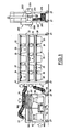
- Fig. 1 illustrates the multi-unit animal caging system :f this invention.
- animal cages 20 are suspended on a rack structure 40 from hollow shelves 22, for example by means of shelf flanges 24.
- the animal cages 20 are equipped with cage flanges 26 which rest on shelf flanges 24 such that the cages 20 can be slideably inserted and withdrawn.
- the system holds cages 20 on both a front side 28 shown in Fig. 1, and a rear side, not shown.
- An air input source 52 draws air into the system.
- the air supply can be conveniently provided by the external system 50 of Fig. 1, ducted into the rack via flexible hoses 54, 56, or the supply can be built into the rack structure 40, for example, in a hollow bottom. To minimize vibration, the external system 50 is preferred.
- the ventilation apparatus 50 supplies air to the cages, and expels air from the system through an exhaust opening 53.
- the system's air input and exhaust may be connected to any appropriate source and to any appropriate discharge, for example, to a permanently-installed room ventilation plant.
- the scheme of the invention is to provide complete duct work as integral parts of the structure supporting the cages.
- air entering at input 52 is filtered and ducted into the rack structure 40 via hose 54.
- End face 42 is internally divided into supply and exhaust ducts which connect with corresponding shelf ducts for supply and exhaust to cages 20. Exhaust air is filtered for particulate matter and ammonia, and is finally expelled at exhaust opening 53.
- Two hollow end faces 42 one end face open to airflow from air input source 52, and another end face to exhaust opening 53 can be constructed on either end of rack structure 40.
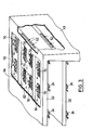
- Such an embodiment is shown in Fig. 3, where the entire depicted hollow side 43 is devoted to air supply, openings to shelves 22 being provided for supply only.
- An opposite hollow end face is necessary, open to airflow from the remaining shelf ducts for exhaust, in the same manner.
- Each hollow shelf 22 is internally lengthwise divided into ducts, for example central duct 62 and two side shelf ducts 64 as integral parts of the shelf.
- the center and side shelf ducts may be separated by dividers within the hollow shelf as shown in Fig. 3. It is preferred, however, that shelf 22 be formed from only two pieces of sheet metal.
- a long sheet 65 forms the entire bottom of shelf 22 and the-top of the side ducts 64.
- a second sheet 63 covers center duct 62 only. This construction is inexpensive, yet ensures complete isolation between supply and exhaust.
- Hollow shelves 11 are shown in Fig. 3 equipped with affles 70 at each cage position.
- the baffles 70 direct airflow nto and out of the cages 20, and minimize eddy currents in the enter shelf duct 62 and side shelf ducts 64.
- the baffles 70 perate to minimize movement of contagion in a direction opposite irflow.
- The-effectiveness of the baffles is increased by their curvature, and by use of larger baffles in the direction of input airflow, and smaller baffles in the direction of exhaust airflow, in keeping with aerodynamic principles.
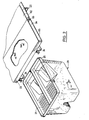
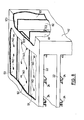
- a duplex type cage 21 is shown in Fig. 2, in position for insertion under shelf 22.
- Water bottles may be mounted in supporting mesh as shown, or water may be supplied in other ways as known in the art.
- Cage 21 is supported below shelf 22 by cage flanges 26 resting on shelf flanges 24. When fully inserted, cage 21 is stopped by protruding ridge 23, under shelf 22.
- shelf flange 24 comprises a flat area 72 at the extreme of travel of cages 20, a sloping area 73 varying the thickness of said shelf flange from thicker at flat area 72 to thinner at the end of sloping area 73, and a lower flat area 74.
- the corresponding cage flange 26 has a width varying from thin at the ends of cage flange 26, sloping along inclined areas 77 to a central flat area 76, said central flat area occurring at a point where the width of the cage flange 26 is substantially equal to the clearance between shelf flange 24 and hollow shelf 22.
- Either cage flange 26 or shelf flange 24, or both, are constructed of a slightly yielding material such as plastic. As cage 20 is inserted.below hollow self 22, little resistance is encountered until the cage flange 26 encounters sloping area 73. When fully inserted, cage 20 is held tightly against hollow shelf 22, the cage flange 26 resting upon central flat area 76.
- the shelf flanges 24 may be constructed to hold two cages, as for the double-sided rack shown, or may be constructed to hold one cage for a single-sided rack such as shown in Fig. 5, in which case the flange 24 would end near the middle of flat area 72.
- Figs. 6 and 7 the dimensions of the flanges are exaggerated for purposes of illustration. In practice, an optimum combination of tight fit and ease of insertion is obtained, as applied to a system for mice, with central flat area 76 of about 3 1/2 inches length, inclined areas 77 of about 4 1/2 inches length, and the width of cage flange 26 varying from about 0.400 inches at central flat area 76 to about 0.370 inches at the corners of cage 20.
- the dimensions of shelf flange 24 correspond to those of the cage flange, whereby a flat shelf flange and the depicted cage flange 26 may be used together, or a flat cage flange and the depicted shelf flange 24, likewise. It is presently preferred that a flat shelf flange be used with the disclosed cage flange.
- FIGs. 1, 5 and 8 illustrate embodiments where only one hollow end face 42 is required.
- hollow end face 42 comprises one wide air supply duct 82 and two air exhaust ducts 1 and 83.
- Each shelf 22 of the rack structure comprises cor--esponding shelf ducts for supply 92 and exhaust 91 and 93.
- upply and exhaust ducts 81, 82, 83 communicate with supply and exhaust shelf ducts 91, 92, 93 through openings or passageways 101, 102, 103 respectively.
- Means are provided for connecting ducts 81, 82 and 83 to an external ventilation system, and are shown in Fig. 1, in the preferred embodiment. It will be appreciated that full width ducts as in Fig. 3, or two duct systems (for a one cage deep system) are also possible.
- integral ducting for a unit having two hollow rack end faces or a single hollow rack end face, as well as appropriate corresponding shelf ducts may be provided as needed for systems of one-deep cages or two-deep cages.
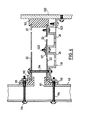
- Fig. 4 illustrates the particulars of interconnection between hollow end face 42 and shelf 22.
- a gasket 111 of rubber or similar material is compressed by bolts 114 and flange members 116, one of which flange members comprises a cage-supporting shelf flange 118.
- Shelf flange 24, of the standard variety is affixed to shelf 22 via machine screw 120 and fastener 121.
- a sheet metal screw could also be used.
- a screw should be provided through shelf flange 24 at the foldover between sheets 65, 63, that is, at junction 66.
- screw 120 affixes shelf flange 24 to shelf 22 and holds the parts of shelf 22 together at the same time.
- a plug 112 of rubber or similar material seals shelf 22.
- This end of shelf 22 must also be supported, however, such support need not contain integral duct work. It is preferred that a standard shelf flange be attached to a rigid support 122, for example by angle member 123.
- Figs. 9 through 11 illustrate an embodiment using valves in closed-lid cages adapted to attach the cages to the air supply and exhaust ducts in the shelves.
- This embodiment is suited to the most demanding of laboratory applications in that it is airtight.
- a cage lid 130 fits tightly over cage 20.
- Cage lid seal ring 132 mounted in groove 131 insures an airtight fit between cage lid 130 and cage 20.
- Air controlling means comprising intake valves and exhaust valves is disposed on the cage lid, in staggered relationship, to mate with openings 140 in the underside of shelf 22. Staggering the valves ensures that the input valve will not cross the output opening, and vice versa, when the cage is inserted or withdrawn.
- the cage 20 and cage lid 130 assembly is installed in the system under shelf 22 by positioning cage flange 26 on shelf flange 24 and sliding the assembly under said shelf, in the same manner as for the open-top cage embodiment.
- the valves are pushed open to open the shelf ducts 91, 92 to the cage, via said valves.
- valves 160 are held normally closed when the cage is not installed, ⁇ he cages are sealed airtight.
- the openings in the shelf ducts are of a size slightly smaller than the bore in the valves. It will be appreciated that only a limited supply of air remains in the cage when removed from the rack.
- Air controlling means comprising baffles 170 are mounted in the openings 140 in shelves 22, to direct airflow into and out of cages 20.
- control of differential air pressure is important because the system leaks to some degree.
- dampers 57, 58 are included to balance the supply and exhaust pressures. To provide maximum occupant protection, the supply pressure is adjusted to exceed the exhaust vacuum, allowing leaking supply and cage air into the room. To provide maximum protection to persons servicing the system, the exhaust vacuum is adjusted to exceed supply pressure, allowing some room air to leak into the cages.
- a system of intermediate effectiveness comprises cage lids but no valves. Rather, a seal ring 162 surrounds the lid openings to seal lid 130 to shelf 22.
- Baffles 170 may be included, or a simple filter may be employed in place of baffles 170 to prevent dander and bedding material from being drawn into the ducts 91, 92, 93 in shelves 22.
- the preferred and most effective embodiment comprises cage lids 130, including valves 160 and seal rings 162 and 131.
- cages sealed by closure of the valves will be immediately transported to a servicing area, for example, to the isolation chamber of Fig. 12 where an operator may open and service the cage by remote control or using sealed gloves.
- a servicing area for example, to the isolation chamber of Fig. 12 where an operator may open and service the cage by remote control or using sealed gloves.
- the re-sealed cage can be disinfected by spraying or dipping, the occupants being safely isolated.
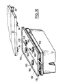
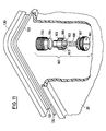
- valves 160 is best illustrated by. Figs. 9, 10 and 11.
- Plastic lid 130 is molded with a protrusion 134 extending downward for attachment of the remaining valve parts.
- the protrusion 134 may have a molded thread, or the thread may be machined into the protrusion after molding.
- Valve seat 164, piston 166 and spring 168 fit into a bore within protrusion 134.
- the bore is of small diameter at the top of lid 130, and larger diameter below, to accommodate the seat and piston.
- Seat 164 is made of a soft plastic material, whereby pressure of piston 166 against seat 164 and seat 164 against lid 130 achieve an airtight fit.
- Piston 166 is axially bored along its upper length only, and radially bored at a point that is covered by seat 164 when the valve is in an upper, closed position, but below and free of seat 164 when the piston is pushed downward to open the valve.
- Spring 168 urges the piston upwards to keep it normally closed, the spring pressing against cap 161 and piston 166.
- Cap 161 is perforated to allow air passing through the bore in piston 166 and thereafter along slots 163 along the lower periphery of the piston, to enter or leave the closed area within cage 20.
- a simple filter pad 167 is mounted in the exhaust valve to prevent larger particles from being drawn into the exhaust to foul the exhaust valve.
- the lid and various valve parts can be made of plastic or metal. It is presently preferred that the lid be a hard clear plastic such as polycarbonate, the seat of a softer plastic or nylon, and the piston, spring and cap of stainless steel.
- the lid In a system for rodents, occupants are inclined to gnaw on any part which protrudes, thereby requiring that unless a mesh 21 as in Fig. 2 is used, at least cap 161 must be made of metal. Moreover, unless some part is available for gnawing, a confined rodent's health will be adversely affected, the teeth growing continuously.
- a seal ring 132 is provided in an indentation in lid 130, as before, which completes an airtight seal when pressed against cage 20.
- External filtration and air impelling means 50 are included in the presently preferred embodiment.
- the depicted fan motor 51 powers both supply and exhaust fans 185, 186.
- a separate motor should be provided in an airtight compartment for each, thereby avoiding contamination of the supply side should the seal fail on the depicted common shaft.
- Room air is blown through input filter and filtered air is blown into the cage ducts via flexible hose 54.
- the filter 180 preferred is a HEPA filter which will remove airborne particles down to about 2 or 3 microns.
- a similar filter is provided on the output side of external means 50 to remove dander and particulate material from air leaving the system.
- activated charcoal filter removes ammonia from the exhaust. While rigid connection may be made between external means 50 and the cage rack, flexible hoses 54, 56 are preferred both for convenience in placement of the units and for better vibration isolation. Dampers control differential pressure, as 'explained above.
- the disclosed system is well suited for transporting as well as housing animals. Wheels provided on the rack structure and the external ventilation unit permit movement of the unit by merely pushing it around. To protect flexible hoses 54, 56 a chain can secure external ventilation unit 50 to the rack structure.
- the ventilation unit can be easily equipped with a rechargeable battery and direct current fan motor for full mobility.
- the embodiment of Fig. 10 comprises a single cage having two input and two output valves.
- the pictured cage can be internally divided below central seal strip 133, using an airtight divider, to match the cage shown in Fig. 2.
- the upper edge of the divider seals against central strip 133 in the same manner that strip 132 seals the outer edges of cage 20 to lid 130.
- Isolation chamber 200 comprises a transparent box 202 having sealed gloves 204 of rubber or plastic extending therein.
- a ventilation system comprising hose 200, fan 222, HEPA filter 224 and charcoal-filter 226 maintains a negative pressure differential between box 202 and the room, and expels only cleaned air into the room.
- the chamber 200 is adapted to interface directly with rack structure 40.
- An operator inserts his hands into gloves 204 and wheels chamber 200 up to the rack front 28.
- Box 202 is then raised or lowered along support bars 206 such that door 208 is placed against the shelf 22 just above the desired cage.
- Counterweight 210 eases raising and lowering of box 202.
- Box 202 is then -lowered, tab 210 contacts shelf 22, and door 208 is opened as the box descends to align with the desired cage.
- the operator may then pull the cage into box 202.
- the operator would again raise box 202 thereby closing door 208.
- the ventilation system can be operated at very high vacuum and door 208 left open. Once confined in box 202, the cage can be opened and the occupants serviced in safety.
Landscapes
- Life Sciences & Earth Sciences (AREA)
- Zoology (AREA)
- Environmental Sciences (AREA)
- Health & Medical Sciences (AREA)
- Animal Behavior & Ethology (AREA)
- Clinical Laboratory Science (AREA)
- General Health & Medical Sciences (AREA)
- Animal Husbandry (AREA)
- Biodiversity & Conservation Biology (AREA)
- Housing For Livestock And Birds (AREA)
- Ventilation (AREA)
Abstract
An improved animal caging system of the type having a plurality of ventilated cages suspended on flanges from a plurality of shelves is provided. The ventilation duct system is entirely enclosed and forms an integral part of the caging system rack. Means mounted in the air ducts for controlling airflow to and from cages, and an arrangement for a tight fit between the cages and the ducts minimize the possibility of cross-infection between occupants of different cages, and between people and cage-occupants. Airtight cages may be employed with valves actuated upon insertion of the cage into the rack, whereby sealed cages may be transported in safety. A negatively pressurized isolation box, adapted to interface with the cage rack, permits manipulation and servicing of cages and occupants, resulting in a contagion-safe total system.
Description
- This invention relates to the field of animal housing, and most advantageously to the housing, servicing and transportation of laboratory animals requiring isolation from contagion or isolation of contagion, using individually removable animal cage units.
- In the art of housing animals, multi-unit systems are employed for a variety of applications. These applications range from pet stores to demanding laboratory experimentation. Problems. that develop when confining a large number of animals in close proximity with one another include unpleasant odors, inadequate air supply, cross-infection and difficulty with installation and removal of individual cage units. In laboratory experimentation applications, animals are usually divided into a subject group and a control group, the subject group receiving a treatment under investigation while the control group is spared. When the subject group in an experiment is subjected to disease organisms, valid experimental results demand that the control group have. absolutely no exposure to the disease in question. In addition, completely pathogen-free animals are required for some experiments. Production of such ultra-pure animals requires the ultimate in isolation.
- Housing a large number of animals poses problems in plying animals with basic needs such as air and food, as well a' the aforesaid problem of infection. In some prior art systems, b ks of animal units have been individually fitted with pipe c. nections to supply and exhaust air, and sometimes to flush refuse from the animal housing unit. When a large number of animal units are mounted in a relatively small space, this maze of individual connections can be a nightmare for the person servicing the animals. This problem is only partially solved in systems that employ press-fit tube connections. On insertion of an animal unit in a system employing press-fit connections, the installer must visually line up the receptacle in the animal unit with the pipe in the rear of the mounting rack before the cage can be put in its final position. Inexact lineup of cages wastes supply air, may introduce pathogens, and may release contagion- bearing exhaust air. The complexity and inconvenience of individually piped systems clearly generates a substantial expense upon purchase and with continuing use, to laboratories that employ them.
- In less demanding applications where some cross-ventilation can be tolerated, former animal housing systems have often employed laminar flow ventilation. In laminar flow ventilation systems, air is supplied via a plenum over an entire bank of animal units. Theoretically, in such a system all the portions of cage ventilation air move parallel to all the other portions, out of the plenum and across the animal units. It is intended that each cage unit receive air directly from the plenum, and discharge air without cross-ventilation to or from other units. Practically, the laminar flow ventilation method is not particularly effective at eliminating cross-ventilation. Discontinuities encountered in the path of the air mass generate eddy currents which preclude uniform air motion. Eddy currents and surface currents produce a random movement of air, sometimes directly opposite the movement-of the larger directed air mass. This phenomenom is analogous to the way a canoeist can be more easily carried up river by staying close to the river bank.
- Laminar air flow systems are generally designed to supply clean air across a bank of cages, then direct the air into the room where the animal housing system.is kept. When laminar air flow systems are so designed to exhaust into the room, persons allergic to the dander of laboratory animals, and all persons in installations where communicable disease experiments are carried out, must be equipped with personal protective equipment. If a plenum is used both on the air supply side and on the exhaust side, not only will the animals be enclosed and unobservable, but insertion and removal of animal units will be extremely inconvenient.
- It will be appreciated that problems with cross-ventilation and problems with convenience of installation and removal often involve a trade-off. If a system is completely airtight, nstallation and removal are likely to be inconvenient, requiring onnection or disconnection of some sort of coupling. Conversely, system which features convenience of installation and removal .ill generally do so at the expense of dependable, airtight ouplings. The present invention seeks to resolve this dichotomy in a system applicable to a range of applications.
- The present invention provides a system whereby the cross-ventilation advantages of an individually-piped system are obtained, as well as the installation and removal convenience of a one-sided laminar flow system. The animal cages are individually removable, yet tapered flanges and gasketing allow the cages to be fitted tightly against the supply and exhaust ducts in a way as effective at reducing cross-ventilation as the individual piping method. Baffles may be mounted in the air ducts to minimize eddy and surface currents, and also help to minimize any cross-ventilation. For the most demanding applications, an airtight valve arrangement provides safe and secure connection. The support rack for the unit is hollow and also serves the function of duct work for supply of air to the individual cages and exhaust therefrom. The system is thus compact and convenient, solving both cross-ventilation and installation-removal problems in one.
- Finally, the system is widely applicable due to inexpensive yet sturdy and dependable construction. In simple embodiment, it is useful in pet stores and non-demanding laboratory work. In a strongly-constructed unit, it is useful as a portable environment for shipping animals. In the most demanding laboratory contagious disease experiments, the full panoply of sealed cages and valves can be used in conjunction with an isolation work chamber for maximum protection. The isolation work chamber is adapted to interface with the cage rack whereby individual cages can be withdrawn, serviced and reinserted. The total system thus can be employed to produce pathogen-free animals or to conduct communicable disease experiments, in addition to merely housing and transporting animals.
- It is the object of this invention to provide a high ensity animal housing system that is as convenient to service as i laminar flow ventilated system, and as effective at reducing cross-ventilation as an individually piped system.
- It is also an object of this invention to minimize the space required for duct work and to more effectively utilize available space for cages and for service of cages in a multi-unit cage system.
- It is also an object of this invention to protect occupants.of a multi-unit cage system from air that has had contact with occupants of other units, and from the dander, refuse and airborne contagion of such other occupants.
- It is another object of this invention to ensure that the occupants of a multi-unit cage system and the human occupants of the area wherein such system is located to not suffer from diseases or allergic reactions caused by cross-ventilation between their air and that of their respective counterparts.
- It is still another object of this invention to provide as airtight a fit as convenience in a range of uses will allow between the cages in a multi-unit caging system and the ducts supplying and exhausting air to and from said cages, while precluding the necessity of careful alignment of cages with the ducts.
- It is yet another object of this invention to provide a total pathogen-protected system for housing and servicing; animals including housing, ventilation and servicing apparatus which interface with one another.
- These and other objects of this invention are accomplished by the animal caging system which comprises: a hollow rack structure having an air input source and an exhaust opening therein; at least one hollow end face mounted on said hollow rack structure and comprising an air supply duct open to air flow from said air input source and an air exhaust duct open to air flow to said exhaust opening; a plurality of hollow shelves disposed between the end faces, each said hollow shelf being internally lengthwise divided into ducts, for example, a center shelf duct and two side shelf ducts; each said hollow shelf having means to support cages which are inserted thereunder, said center shelf ducts being open to air flow from said air supply duct, and having openings to each cage suspended thereunder and means for controlling air flow from said center shelf duct into the cage below, said side shelf ducts being open to air flow to said exhaust duct, and having openings from.each cage suspended thereunder and means for controlling air flow into said side shelf duct from the cage below, said cages being constructed of material impervious to air, and closed on all sides except as required for air flow.
- The openings between the cages and the air supply and exhaust ducts may be fitted with baffles directing air into and at of the cages, in an embodiment with cages having open tops. A 3re airtight connection may be achieved in another embodiment by 3e of cage lids. Sealing rings of rubber or other flexible aterial are fitted in depressions along the surfaces of the lids etween the cage lids and flanges on the upper edge of the cage bodies and between air openings in the lids and the ducted shelves. The lids may also comprise valves mounted in air openings the valves having spring-loaded pistons. When a cage is inserted, the valves are forced open to supply and exhaust air. Upon removal of a cage, the valves close by release of the pistons to prevent the escape or access of contagion.
- In alternative embodiments, one hollow end face comprising two supply and two exhaust ducts, or two hollow end faces, one a supply duct and one an exhaust duct, are provided. The shelves are divided into shelf ducts open to the appropriate supply and exhaust ducts at the ends thereof.
- A tight fit between the cages and the hollow shelves is accomplished by the aforesaid system also comprising: flat shelf flanges mounted under each hollow self; and, cage flanges along the top edge of said cages, upon which said cages are slideably insertable and removable along said shelf flanges, each said cage flange having a thicker flat center area, and two sloping areas to either thinner end of said cage flange, said thicker flat center area being of the same thickness as the space between said shelf flange and said hollow shelf. A like result is obtained in a system wherein said shelf flanges mounted under each said hollow shelf have two sloping areas from a thinner central area to thicker short flat areas at either end of said shelf flange; and said cage flanges along the top edge of said cages are flat, and of the same thickness as the space between said hollow shelf and said short flat areas at either end of said shelf flange. In either of the foregoing embodiments, the effect is to press the inserted cage against the shelf duct.
- In an embodiment employing open-top cages, the means for controlling air flow comprises baffles disposed in the openings between said hollow shelves and said cages, and curved in a direction opposite air flow. The baffles are of increasing length and width in the direction of air flow for those openings in said air supply duct, and of decreasing length and width in the direction of air flow in said exhaust duct. One embodiment is disclosed with air filtration and impelling means housed in a hollow bottom of the rack structure, provided for the air input, the air output, or both. Another system is disclosed with means for connecting the rack structure to an external ventilating system, whereby the vibration of the ventilating system is removed from the occupants of the cages.
- For maximum isolation, valved closed-top cages are employed in conjunction with a mobile isolation work chamber. The work chamber interfaces with the cage rack to permit insertion and removal of cages directly to and from the work chamber.
- For the purpose of illustrating the invention, there .re shown in the drawings forms which are presently preferred; it being understood, however, that this invention is not limited to the precise arrangements and instrumentalities shown.
- Fig. 1 is a plan view of the complete system, the ventilation apparatus shown cutaway;
- Fig. 2 is a perspective view illustrating installation and removal of a typical animal unit in a system having open-top cages;
- Fig. 3 is a perspective breakout view showing ducting . and baffle arrangements within the system framework;
- Fig. 4 is a plan view of a cross-section of a self and duct;
- Fig. 5 is a perspective view of a system rack for a single depth embodiment;
- Fig. 6 is a perspective view of a shelf flange for use with a flat cage flange;
- Fig. 7 is a perspective view of a cage flange for use with a flat shelf flange;
- Fig. 8 is a perspective breakout view of an alternative duct and shelf duct arrangement;
- Figs. 9(a) and 9(b) are section views of cage valves for output and input, respectively, Fig. 9(b) illustrating, in cross-section, the connection of shelf, lid and cage;
- Fig. 10 is a perspective view of an embodiment featuring maximum airtight construction, employing a valved and fully sealed cage lid;
- Fig. 11 is an exploded cutaway view of a lid, valve and cage; and,
- Fig. 12 is a perspective view of an isolation chamber according to the invention.
- Fig. 1 illustrates the multi-unit animal caging system :f this invention. As also shown in Fig. 2, in a multi-unit system of this kind,
animal cages 20 are suspended on arack structure 40 fromhollow shelves 22, for example by means ofshelf flanges 24. Theanimal cages 20 are equipped withcage flanges 26 which rest onshelf flanges 24 such that thecages 20 can be slideably inserted and withdrawn. The system holdscages 20 on both afront side 28 shown in Fig. 1, and a rear side, not shown. - An
air input source 52 draws air into the system. The air supply can be conveniently provided by theexternal system 50 of Fig. 1, ducted into the rack viaflexible hoses rack structure 40, for example, in a hollow bottom. To minimize vibration, theexternal system 50 is preferred. Theventilation apparatus 50 supplies air to the cages, and expels air from the system through anexhaust opening 53. The system's air input and exhaust may be connected to any appropriate source and to any appropriate discharge, for example, to a permanently-installed room ventilation plant. - The scheme of the invention is to provide complete duct work as integral parts of the structure supporting the cages. With reference to Fig. 1, air entering at
input 52 is filtered and ducted into therack structure 40 viahose 54.End face 42 is internally divided into supply and exhaust ducts which connect with corresponding shelf ducts for supply and exhaust tocages 20. Exhaust air is filtered for particulate matter and ammonia, and is finally expelled atexhaust opening 53.End face 42 of the rack structure, hollow and forming integral ducts as shown in Figs. 5 and 8, connects air supply and exhaust to theintegral ducts hollow shelf 22. Two hollow end faces 42, one end face open to airflow fromair input source 52, and another end face toexhaust opening 53 can be constructed on either end ofrack structure 40. Such an embodiment is shown in Fig. 3, where the entire depictedhollow side 43 is devoted to air supply, openings toshelves 22 being provided for supply only. An opposite hollow end face is necessary, open to airflow from the remaining shelf ducts for exhaust, in the same manner. - Each
hollow shelf 22 is internally lengthwise divided into ducts, for examplecentral duct 62 and twoside shelf ducts 64 as integral parts of the shelf. The center and side shelf ducts may be separated by dividers within the hollow shelf as shown in Fig. 3. It is preferred, however, thatshelf 22 be formed from only two pieces of sheet metal. As shown in Fig. 2, along sheet 65 forms the entire bottom ofshelf 22 and the-top of theside ducts 64. A second sheet 63 coverscenter duct 62 only. This construction is inexpensive, yet ensures complete isolation between supply and exhaust. - Hollow shelves 11 are shown in Fig. 3 equipped with
affles 70 at each cage position. Thebaffles 70 direct airflow nto and out of thecages 20, and minimize eddy currents in theenter shelf duct 62 andside shelf ducts 64. Thebaffles 70 perate to minimize movement of contagion in a direction opposite irflow. The-effectiveness of the baffles is increased by their curvature, and by use of larger baffles in the direction of input airflow, and smaller baffles in the direction of exhaust airflow, in keeping with aerodynamic principles. - A
duplex type cage 21 is shown in Fig. 2, in position for insertion undershelf 22. Water bottles may be mounted in supporting mesh as shown, or water may be supplied in other ways as known in the art.Cage 21 is supported belowshelf 22 bycage flanges 26 resting onshelf flanges 24. When fully inserted,cage 21 is stopped by protrudingridge 23, undershelf 22. - Figs. 6 and 7. illustrate means for achieving a tight fit between
cages 20 andhollow shelves 22 to minimize cross-ventilation. In Fig. 6,shelf flange 24 comprises aflat area 72 at the extreme of travel ofcages 20, a slopingarea 73 varying the thickness of said shelf flange from thicker atflat area 72 to thinner at the end of slopingarea 73, and a lowerflat area 74. The correspondingcage flange 26 has a width varying from thin at the ends ofcage flange 26, sloping alonginclined areas 77 to a centralflat area 76, said central flat area occurring at a point where the width of thecage flange 26 is substantially equal to the clearance betweenshelf flange 24 andhollow shelf 22. Eithercage flange 26 orshelf flange 24, or both, are constructed of a slightly yielding material such as plastic. Ascage 20 is inserted.belowhollow self 22, little resistance is encountered until thecage flange 26encounters sloping area 73. When fully inserted,cage 20 is held tightly againsthollow shelf 22, thecage flange 26 resting upon centralflat area 76. The shelf flanges 24 may be constructed to hold two cages, as for the double-sided rack shown, or may be constructed to hold one cage for a single-sided rack such as shown in Fig. 5, in which case theflange 24 would end near the middle offlat area 72. - In Figs. 6 and 7 the dimensions of the flanges are exaggerated for purposes of illustration. In practice, an optimum combination of tight fit and ease of insertion is obtained, as applied to a system for mice, with central
flat area 76 of about 3 1/2 inches length,inclined areas 77 of about 4 1/2 inches length, and the width ofcage flange 26 varying from about 0.400 inches at centralflat area 76 to about 0.370 inches at the corners ofcage 20. The dimensions ofshelf flange 24 correspond to those of the cage flange, whereby a flat shelf flange and the depictedcage flange 26 may be used together, or a flat cage flange and the depictedshelf flange 24, likewise. It is presently preferred that a flat shelf flange be used with the disclosed cage flange. - Figs. 1, 5 and 8 illustrate embodiments where only one
hollow end face 42 is required. In Fig. 8,hollow end face 42 comprises one wideair supply duct 82 and twoair exhaust ducts shelf 22 of the rack structure comprises cor--esponding shelf ducts forsupply 92 andexhaust exhaust ducts exhaust shelf ducts passageways ducts - To summarize the foregoing, integral ducting for a unit having two hollow rack end faces or a single hollow rack end face, as well as appropriate corresponding shelf ducts may be provided as needed for systems of one-deep cages or two-deep cages..
- Fig. 4 illustrates the particulars of interconnection between
hollow end face 42 andshelf 22. On the end ofshelf 22 where the same are attached, agasket 111 of rubber or similar material is compressed bybolts 114 andflange members 116, one of which flange members comprises a cage-supportingshelf flange 118.Shelf flange 24, of the standard variety, is affixed toshelf 22 viamachine screw 120 andfastener 121. A sheet metal screw could also be used. With reference to Fig. 2, a screw should be provided throughshelf flange 24 at the foldover betweensheets 65, 63, that is, atjunction 66. By this means, screw 120 affixesshelf flange 24 toshelf 22 and holds the parts ofshelf 22 together at the same time. - At the end of
shelf 22opposite end face 42, aplug 112 of rubber or similarmaterial seals shelf 22. This end ofshelf 22 must also be supported, however, such support need not contain integral duct work. It is preferred that a standard shelf flange be attached to arigid support 122, for example byangle member 123. - Figs. 9 through 11 illustrate an embodiment using valves in closed-lid cages adapted to attach the cages to the air supply and exhaust ducts in the shelves. This embodiment is suited to the most demanding of laboratory applications in that it is airtight. A
cage lid 130 fits tightly overcage 20. Cagelid seal ring 132 mounted ingroove 131 insures an airtight fit betweencage lid 130 andcage 20. Air controlling means comprising intake valves and exhaust valves is disposed on the cage lid, in staggered relationship, to mate withopenings 140 in the underside ofshelf 22. Staggering the valves ensures that the input valve will not cross the output opening, and vice versa, when the cage is inserted or withdrawn. - The
cage 20 andcage lid 130 assembly is installed in the system undershelf 22 by positioningcage flange 26 onshelf flange 24 and sliding the assembly under said shelf, in the same manner as for the open-top cage embodiment. When the cage is fully inserted, however, the valves are pushed open to open theshelf ducts valves 160 are held normally closed when the cage is not installed, ÷he cages are sealed airtight. The openings in the shelf ducts are of a size slightly smaller than the bore in the valves. It will be appreciated that only a limited supply of air remains in the cage when removed from the rack. - Alternative air controlling means are also disclosed, for use in less demanding applications. Where cross-ventilation is tolerable, open top (i.e., lidless) cages are employed as in Fig. 2. Air controlling means comprising baffles 170 are mounted in the
openings 140 inshelves 22, to direct airflow into and out ofcages 20. In such a system, control of differential air pressure is important because the system leaks to some degree. With reference to Fig. 1,dampers - A system of intermediate effectiveness comprises cage lids but no valves. Rather, a
seal ring 162 surrounds the lid openings to seallid 130 toshelf 22. Baffles 170 may be included, or a simple filter may be employed in place of baffles 170 to prevent dander and bedding material from being drawn into theducts shelves 22. The preferred and most effective embodiment comprisescage lids 130, includingvalves 160 andseal rings - It is presently contemplated that cages sealed by closure of the valves will be immediately transported to a servicing area, for example, to the isolation chamber of Fig. 12 where an operator may open and service the cage by remote control or using sealed gloves. Upon completion, the re-sealed cage can be disinfected by spraying or dipping, the occupants being safely isolated.
- The operation of
valves 160 is best illustrated by. Figs. 9, 10 and 11.Plastic lid 130 is molded with aprotrusion 134 extending downward for attachment of the remaining valve parts. Theprotrusion 134 may have a molded thread, or the thread may be machined into the protrusion after molding. -
Valve seat 164,piston 166 andspring 168 fit into a bore withinprotrusion 134. The bore is of small diameter at the top oflid 130, and larger diameter below, to accommodate the seat and piston.Seat 164 is made of a soft plastic material, whereby pressure ofpiston 166 againstseat 164 andseat 164 againstlid 130 achieve an airtight fit.Piston 166 is axially bored along its upper length only, and radially bored at a point that is covered byseat 164 when the valve is in an upper, closed position, but below and free ofseat 164 when the piston is pushed downward to open the valve.Spring 168 urges the piston upwards to keep it normally closed, the spring pressing againstcap 161 andpiston 166.Cap 161 is perforated to allow air passing through the bore inpiston 166 and thereafter alongslots 163 along the lower periphery of the piston, to enter or leave the closed area withincage 20. Asimple filter pad 167 is mounted in the exhaust valve to prevent larger particles from being drawn into the exhaust to foul the exhaust valve. - The lid and various valve parts can be made of plastic or metal. It is presently preferred that the lid be a hard clear plastic such as polycarbonate, the seat of a softer plastic or nylon, and the piston, spring and cap of stainless steel. In a system for rodents, occupants are inclined to gnaw on any part which protrudes, thereby requiring that unless a
mesh 21 as in Fig. 2 is used, at leastcap 161 must be made of metal. Moreover, unless some part is available for gnawing, a confined rodent's health will be adversely affected, the teeth growing continuously. Aseal ring 132 is provided in an indentation inlid 130, as before, which completes an airtight seal when pressed againstcage 20. - External filtration and air impelling means 50, as depicted in Fig. 1 are included in the presently preferred embodiment. The depicted
fan motor 51 powers both supply andexhaust fans flexible hose 54. Thefilter 180 preferred is a HEPA filter which will remove airborne particles down to about 2 or 3 microns. A similar filter is provided on the output side ofexternal means 50 to remove dander and particulate material from air leaving the system. In addition, activated charcoal filter removes ammonia from the exhaust. While rigid connection may be made betweenexternal means 50 and the cage rack,flexible hoses - The disclosed system is well suited for transporting as well as housing animals. Wheels provided on the rack structure and the external ventilation unit permit movement of the unit by merely pushing it around. To protect
flexible hoses 54, 56 a chain can secureexternal ventilation unit 50 to the rack structure. The ventilation unit can be easily equipped with a rechargeable battery and direct current fan motor for full mobility. - The embodiment of Fig. 10 comprises a single cage having two input and two output valves. The pictured cage can be internally divided below
central seal strip 133, using an airtight divider, to match the cage shown in Fig. 2. The upper edge of the divider seals againstcentral strip 133 in the same manner that strip 132 seals the outer edges ofcage 20 tolid 130. In conjunction with theisolation chamber 200 of Fig. 12, the foregoing comprises a complete animal care system.Isolation chamber 200 comprises atransparent box 202 having sealedgloves 204 of rubber or plastic extending therein. A ventilationsystem comprising hose 200,fan 222,HEPA filter 224 and charcoal-filter 226 maintains a negative pressure differential betweenbox 202 and the room, and expels only cleaned air into the room. - The
chamber 200 is adapted to interface directly withrack structure 40. An operator inserts his hands intogloves 204 andwheels chamber 200 up to therack front 28.Box 202 is then raised or lowered along support bars 206 such thatdoor 208 is placed against theshelf 22 just above the desired cage.Counterweight 210 eases raising and lowering ofbox 202.Box 202 is then -lowered,tab 210contacts shelf 22, anddoor 208 is opened as the box descends to align with the desired cage. The operator may then pull the cage intobox 202. Preferably, the operator would again raisebox 202 thereby closingdoor 208. However, the ventilation system can be operated at very high vacuum anddoor 208 left open. Once confined inbox 202, the cage can be opened and the occupants serviced in safety. - Further variations on the inventive concept disclosed herein are possible and will now be apparent to those skilled in the art. Reference should be made to the appended Claims rather than the foregoing Specification as defining the true scope of this invention.
Claims (13)
1. A contagion-safe animal housing system comprising:
(a) a plurality of airtight animal cages mounted in a rack;
(b) means for supplying and exhausting air to and from said cages;
(c) means for servicing said cages comprising means for accessing and withdrawing the cages from the system directly into an airtight service area.
2. The animal housing system of Claim 1, wherein said means for servicing comprises an isolation box having sealed gloves extending therein, said box being mounted on a mobile carriage, whereby said isolation box can be transported to the vicinity of said cages.
3. The animal housing system of Claim 2, wherein said isolation box comprises a door upon a surface thereof-, said door openable by moving said box against said rack, whereby an operator may withdraw said cages by pulling the same through said door while using said sealed gloves.
4. The animal housing system of anyone of claims 1 to 3 further comprising ventilation means adapted to maintain a negative pressure differential between said service area and a space surrounding said system, whereby any contagion which may be released in said service area will be drawn into said ventilation means.
5. The animal housing system of claims 2 or 3, wherein said isolation box is moveable upon said mobile carriage, and said door comprises a contact tab adapted to engage said rack when said box is moved relative to said door.
6. A contagion-safe animal housing system of the type having hollow cages supported by a hollow rack structure, said system comprising:
(a) a source of clean air, and a discharge for exhaust air;
(b) a hollow rack structure both directing the clean air to animal cages supported thereby, and directing the exhaust air from said cages to said discharge.
(c) means for controlling airflow disposed between said rack structure and said cages.
7. The animal housing system of Claim 6, wherein the cages are supported by hollow shelves internally lengthwise divided into shelf ducts directing said clean air and said exhaust air to and from said cages, said shelf ducts being closed at one end thereof and open at an opposite end thereof to at least one hollow end face of said rack structure, said at least one hollow end face having integral ducts communicating with said source and said discharge and in which preferably said shelf ducts are each closed at the same one end thereof and open at the same opposite end thereof to a single hollow end face, said single hollow end face being internally lengthwise divided into at least one supply duct and at least one exhaust duct communicating with said source and said discharge.
8. The animal housing system of Claim 6 or 7, further comprising means for controlling airflow mounted between said shelf ducts and said cages suspended thereunder, and which preferably comprises baffles mounted in a lower surface of said shelf ducts, whereby air is directed into and out of said cages from said supply and to said discharge.
9. The animal housing system of Claim 7 or 8, wherein said cages comprise cage flanges along an upper edge thereof, and are supported along said cage flanges by shelf flanges, said shelf flanges being substantially flat and said cage flanges being thicker at a central flat area and sloping to thinner at either end of said cage flanges, said central flat area of substantially the same thickness as is space between said shelf duct and said shelf flange, whereby said cages can be easily inserted but upon insertion are pushed against said shelf ducts.
10. The animal housing system of Claim 8 or 9, further comprising cage lids disposed in airtight relationship between said cages and said shelf ducts, the lids having holes aligned with openings in the shelf ducts for passage of air, and wherein preferably said means for controlling airflow comprises valves having actuation means disposed between said cages and said shelf ducts, said valves adapted to open upon insertion of the cage into the rack structure, and to close upon withdrawal thereof, and wherein particularly said valves comprise valve seats disposed in said lids, said actuation means comprising spring-loaded pistons extending beyond said lids when said valves are closed, said pistons being axially bored through a portion thereof, and radially bored through the axial bore at a portion of said pistons which is moveably positioned to communicate with spaces within said cages when said cages are inserted into the rack structure, and moveably positioned to seal against said valve seat when said cages are withdrawn, said moveable positioning being actuated by contact between said pistons and said shelf ducts when the cages are inserted and withdrawn from the rack.
11. The animal housing system of Claim 10 further comprising seal rings disposed on said cage lids and extending therefrom, said seal rings adapted to seal the lids to the shelf ducts when the cages are inserted into said rack, and wherein said cages are preferably of double width, being joined in sealed pairs having a single lid, said lid having at least four means for controlling airflow mounted therein, means for controlling input airflow and means for controlling exhaust airflow being provided in staggered relationship for each cage.
12. The animal housing system of Claim 11, further comprising second seal rings disposed in grooves on said cage lids said second seal rings adapted to seal said lids to each of said cages.
13. The animal housing system of anyone of the claims 6 to 12, comprising wheels disposed on said rack structure, said source of clean air and said discharge for exhaust air, whereby said animal housing system is self-contained and operable to transport animals.
Applications Claiming Priority (2)
| Application Number | Priority Date | Filing Date | Title |
|---|---|---|---|
| US206058 | 1980-11-12 | ||
| US06/206,058 US4343261A (en) | 1979-09-18 | 1980-11-12 | Animal caging system |
Publications (2)
| Publication Number | Publication Date |
|---|---|
| EP0051876A2 true EP0051876A2 (en) | 1982-05-19 |
| EP0051876A3 EP0051876A3 (en) | 1983-01-26 |
Family
ID=22764800
Family Applications (1)
| Application Number | Title | Priority Date | Filing Date |
|---|---|---|---|
| EP81109611A Withdrawn EP0051876A3 (en) | 1980-11-12 | 1981-11-11 | Animal caging system |
Country Status (3)
| Country | Link |
|---|---|
| US (1) | US4343261A (en) |
| EP (1) | EP0051876A3 (en) |
| JP (1) | JPS5783233A (en) |
Cited By (11)
| Publication number | Priority date | Publication date | Assignee | Title |
|---|---|---|---|---|
| EP0238559A4 (en) * | 1985-09-30 | 1988-02-08 | Peter Best Graham | Isolation cabinet. |
| FR2606969A1 (en) * | 1986-11-26 | 1988-05-27 | Plouvier Maurice | Cell for raising animals |
| EP0724828A3 (en) * | 1995-01-31 | 1997-06-25 | Gazzada Tecniplast Srl | Animal husbandry container |
| WO1999028463A3 (en) * | 1997-12-01 | 1999-09-10 | American Nat Red Cross | Methods for the degradation and detoxification of organic material using urine produced by transgenic animals |
| WO2001032006A1 (en) * | 1999-11-05 | 2001-05-10 | Lab Products Inc. | Double sided work station |
| WO2001033948A1 (en) * | 1999-11-05 | 2001-05-17 | Adam Cohen | Environmental monitoring and control system for a ventilated cage and rack system |
| WO2002035920A3 (en) * | 2000-11-03 | 2002-11-07 | Products Lab Inc | Animal isolation and caging system |
| KR100425938B1 (en) * | 2002-01-17 | 2004-04-14 | 박천귀 | The air supplying double safety valve for lab animal isolation cage |
| ES2211360A1 (en) * | 2003-11-14 | 2004-07-01 | Probitas Pharma, S.A. | Facility for animal husbandry, particularly for experimental animals, has frame with movable support, where trays are placed on floor, and frame is provided with multiple cantilever arms on side tabs |
| WO2016179626A1 (en) | 2015-05-11 | 2016-11-17 | Bigcity Design Pty Ltd | Modular animal accommodation |
| CN107041315A (en) * | 2017-06-02 | 2017-08-15 | 苏州新区枫桥净化设备有限公司 | A kind of subregion maintenance type pet cage |
Families Citing this family (77)
| Publication number | Priority date | Publication date | Assignee | Title |
|---|---|---|---|---|
| US4526133A (en) * | 1984-03-05 | 1985-07-02 | Schroer Manufacturing Co., Inc. | Animal isolation cage ward |
| US4528941A (en) * | 1984-05-07 | 1985-07-16 | Spengler Charles W | Free-standing environmental chambers supported by plenum |
| US4690100A (en) * | 1985-10-22 | 1987-09-01 | Thoren Caging Systems, Inc. | Ventilated animal housing and service system with cage filter covers |
| US4781146A (en) * | 1986-04-21 | 1988-11-01 | Spengler Charles W | Aerosol testing chamber for experimental animals |
| US4917046A (en) * | 1986-04-21 | 1990-04-17 | Spengler Charles W | Aerosol testing method and chamber for experimental animals |
| JPH0333253Y2 (en) * | 1986-10-03 | 1991-07-15 | ||
| JPH0438702Y2 (en) * | 1986-10-23 | 1992-09-10 | ||
| JPH0313176Y2 (en) * | 1986-12-23 | 1991-03-27 | ||
| US5042429A (en) * | 1989-01-25 | 1991-08-27 | Lab Products, Inc. | Ventilated cage and rack system |
| DE3908336A1 (en) * | 1989-03-15 | 1990-09-20 | Salmet Gmbh & Co Kg | DRIVE FOR AIRFLOW DEVICE OF A CAGE BATTERY FOR THE POULTRY KEEPING |
| US5000120A (en) * | 1989-10-25 | 1991-03-19 | Allentown Caging Equipment Co., Inc. | Animal caging assembly with a ventilation system |
| US5044316A (en) * | 1990-03-28 | 1991-09-03 | Thoren Caging Systems, Inc. | Ventilated animal caging system with cage racks and filter covers including valves operable by rack |
| US5349923A (en) * | 1990-04-27 | 1994-09-27 | Lab Products | Ventilated cage and open rack system |
| US4989545A (en) * | 1990-04-27 | 1991-02-05 | Lab Products, Inc. | Ventilated cage and open rack system |
| US5083558A (en) * | 1990-11-06 | 1992-01-28 | Thomas William R | Mobile surgical compartment with micro filtered laminar air flow |
| US5148766A (en) * | 1991-12-12 | 1992-09-22 | Allentown Caging Equipment Co., Inc. | Ventilated rack and animal cage system |
| US5307757A (en) * | 1991-12-12 | 1994-05-03 | Allentown Caging Equipment Co., Inc. | Ventilated rack and animal cage system |
| US5477810A (en) * | 1993-06-24 | 1995-12-26 | Wilkison, Iii; Ralph C. | Aviary air filter |
| US5385118A (en) * | 1993-12-21 | 1995-01-31 | Allentown Caging Equipment Co., Inc. | Assembly for animals with positive disconnect from a watering system |
| US5400744A (en) * | 1994-04-18 | 1995-03-28 | Allentown Caging Co., Inc. | Leakproof locking sterile water valve system |
| US5474024A (en) * | 1994-10-04 | 1995-12-12 | Thoren Caging Systems, Inc. | Caging system with slide bar operator for quick disconnect water fitting |
| US6382589B1 (en) | 1996-02-14 | 2002-05-07 | Edstrom Industries, Inc. | Latch mechanism and quick-connect coupling usable with automatic water docking system for cage and rack systems |
| US5823144A (en) * | 1996-02-14 | 1998-10-20 | Edstrom Industries, Inc. | Cage and rack system incorporating automatic water docking system, latch mechanism, and quick-connect coupling |
| USD399609S (en) | 1997-04-01 | 1998-10-13 | The Mason Company | Veterinary isolation cage |
| US6257171B1 (en) | 1998-01-16 | 2001-07-10 | Animal Care Systems, Inc. | Animal caging and biological storage systems |
| US6341579B1 (en) * | 1998-05-07 | 2002-01-29 | William E. Alkire | Litter box filter system |
| US6058886A (en) * | 1998-08-26 | 2000-05-09 | Schroer Manufacturing Company | Pet cage dryer |
| US6308660B1 (en) | 1999-06-17 | 2001-10-30 | Allentown Caging Equipment Co., Inc. | Bio-containment animal cage system |
| US6305324B1 (en) | 1999-11-05 | 2001-10-23 | Thoren Caging Systems, Inc. | High density housing for aquatic animals |
| US6357393B1 (en) | 2000-06-28 | 2002-03-19 | Allentown Caging Equipment Co., Inc. | Device for automatically controlling exhaust flow to a rack for animal cages |
| US6408794B1 (en) | 2000-10-20 | 2002-06-25 | Allentown Caging Equipment Co., Inc. | Device for displaying an air flow condition in a rack for animal cages |
| EP1454523A4 (en) * | 2001-12-14 | 2005-03-16 | Osaka Ind Promotion Org | ANIMAL BREEDING SYSTEM AND USE THEREOF |
| WO2003059048A1 (en) * | 2002-01-17 | 2003-07-24 | Chean-Gui Park | Cage for breeding of lab animal |
| US6553939B1 (en) * | 2002-02-08 | 2003-04-29 | Getinge/Castle, Inc. | Method of changing the cages of laboratory animals, and racks for use therewith |
| AU2003287230A1 (en) * | 2002-10-25 | 2004-05-13 | Lab Products, Inc. | Animal cage and rack system |
| US7036457B2 (en) * | 2003-09-11 | 2006-05-02 | Tonets Corporation | Rodent housing rack |
| KR20050040008A (en) * | 2003-10-27 | 2005-05-03 | 삼성전자주식회사 | Glass substrate lifter and glass substrate lifting system |
| US6889628B1 (en) | 2003-11-04 | 2005-05-10 | Icbp | Corn cob chew toy |
| AU2005201553B2 (en) * | 2004-04-14 | 2011-08-11 | Airlaw Pty Ltd | Animal caging system |
| US20060011143A1 (en) * | 2004-07-14 | 2006-01-19 | Drummond Robert A | Laboratory animal housing with euthanizing function |
| US20070169714A1 (en) * | 2004-12-13 | 2007-07-26 | Innovive Inc. | Containment systems and components for animal husbandry |
| US8082885B2 (en) | 2004-12-13 | 2011-12-27 | Innovive, Inc. | Containment systems and components for animal husbandry: rack module assembly method |
| CA2590865C (en) * | 2004-12-13 | 2014-04-22 | Innovive, Inc. | Containment systems and components for animal husbandry |
| US7739984B2 (en) | 2004-12-13 | 2010-06-22 | Innovive, Inc. | Containment systems and components for animal husbandry: cage racks |
| US20070175399A1 (en) * | 2004-12-13 | 2007-08-02 | Innovive Inc. | Containment systems and components for animal husbandry |
| US20070169715A1 (en) * | 2004-12-13 | 2007-07-26 | Innovive Inc. | Containment systems and components for animal husbandry |
| US7874268B2 (en) | 2004-12-13 | 2011-01-25 | Innovive, Inc. | Method for adjusting airflow in a rodent containment cage |
| US7734381B2 (en) | 2004-12-13 | 2010-06-08 | Innovive, Inc. | Controller for regulating airflow in rodent containment system |
| US8156899B2 (en) | 2004-12-13 | 2012-04-17 | Innovive Inc. | Containment systems and components for animal husbandry: nested covers |
| US7661392B2 (en) * | 2004-12-13 | 2010-02-16 | Innovive, Inc. | Containment systems and components for animal husbandry: nested cage bases |
| USD533971S1 (en) | 2004-12-29 | 2006-12-19 | Animal Care Systems, Inc. | Animal cage |
| JP4571535B2 (en) * | 2005-05-13 | 2010-10-27 | ダイダン株式会社 | Rack equipment for breeding laboratory animals |
| US7954455B2 (en) | 2005-06-14 | 2011-06-07 | Innovive, Inc. | Cage cover with filter, shield and nozzle receptacle |
| US20070193527A1 (en) * | 2005-10-03 | 2007-08-23 | Richard Verhage | Ventilated animal cage assembly |
| US7594481B2 (en) * | 2005-10-11 | 2009-09-29 | Animal Care Systems, Inc. | Carousel animal caging system with a centralized water supply and ventilation plenum |
| US20070181070A1 (en) * | 2005-12-13 | 2007-08-09 | Innovive Inc. | Containment systems and components for animal husbandry |
| US20070181075A1 (en) * | 2005-12-13 | 2007-08-09 | Innovive Inc. | Containment systems and components for animal husbandry |
| US20110061600A1 (en) * | 2006-08-17 | 2011-03-17 | Innovive, Inc. | Containment systems and components for animal husbandry |
| US20080087231A1 (en) * | 2006-10-13 | 2008-04-17 | Gabriel George S | Cage and rack system |
| US20080134984A1 (en) * | 2006-10-13 | 2008-06-12 | Conger Dee L | Containment cage liners for animal husbandry |
| US7798171B2 (en) * | 2006-10-13 | 2010-09-21 | Lab Products, Inc. | Valve assembly |
| CA2683257A1 (en) * | 2007-04-11 | 2008-10-23 | Innovive, Inc. | Animal husbandry drawer caging |
| US7895977B2 (en) * | 2007-05-10 | 2011-03-01 | The United States Of America As Represented By The Secretary Of The Army | Device for the safe handling of nonhuman primates |
| WO2010054257A2 (en) * | 2008-11-07 | 2010-05-14 | Innovive, Inc. | Rack system and monitoring for animal husbandry |
| ITMI20091045A1 (en) * | 2009-06-12 | 2010-12-13 | Tecniplast Spa | VENTILATED SHELF, PARTICULARLY FOR STABULARS, EQUIPPED WITH ANTI-PARTICULATE FILTER |
| US20110139086A1 (en) * | 2009-12-16 | 2011-06-16 | David Burgener | Method, Apparatus, and System for Euthanizing Large Numbers of Animals with Solid Carbon Dioxide |
| EP2627169B1 (en) | 2010-10-11 | 2019-12-18 | Innovive, Inc. | Rodent containment cage monitoring method |
| US20120272919A1 (en) * | 2011-04-26 | 2012-11-01 | The University Of Utah | Animal euthanasia systems and methods |
| JP5583108B2 (en) * | 2011-12-08 | 2014-09-03 | トキワ科学器械株式会社 | Breeding device and dust collection method |
| WO2015002843A1 (en) | 2013-07-01 | 2015-01-08 | Innovive, Inc. | Cage rack monitoring apparatus and methods |
| US10842124B2 (en) | 2014-07-25 | 2020-11-24 | Innovive, Inc. | Animal containment enrichment compositions and methods |
| ITUB20150583A1 (en) * | 2015-04-14 | 2016-10-14 | Tecniplast Spa | STABULATION CAGE FOR LABORATORY ANIMALS |
| WO2016196660A1 (en) | 2015-06-01 | 2016-12-08 | Charles River Laboratories, Inc. | Detection of infectious agents from environmental air dust |
| WO2018081434A1 (en) | 2016-10-28 | 2018-05-03 | Innovive, Inc. | Metabolic caging |
| US11337404B2 (en) * | 2018-02-01 | 2022-05-24 | The Boeing Company | Vehicle, ventilation system, and method for transporting pets |
| CN109566432B (en) * | 2018-12-28 | 2021-03-16 | 温州医科大学 | An IVC independent air supply isolation device |
| CN112504324B (en) * | 2019-09-16 | 2022-05-24 | 武汉世纪久海检测技术有限公司 | Method for detecting air exchange times of independent ventilation cage box |
Family Cites Families (58)
| Publication number | Priority date | Publication date | Assignee | Title |
|---|---|---|---|---|
| US1863982A (en) * | 1928-09-13 | 1932-06-21 | Union Steel Prod Co | Poultry coop or crate |
| US1839673A (en) * | 1929-03-15 | 1932-01-05 | Spratt S Patent America Ltd | Exhibition bench |
| US1823584A (en) * | 1930-11-12 | 1931-09-15 | Barker Poultry Equipment Compa | Brooder ventilation structure |
| US2129786A (en) * | 1934-11-10 | 1938-09-13 | Charles E Sacre | Cage |
| GB462557A (en) | 1935-09-28 | 1937-03-11 | Horace Arthur Pyrah | Warming or cooling and ventilating plant for housed chicken brooders |
| US2335173A (en) * | 1941-09-29 | 1943-11-23 | Emmett H Corey | Means for ventilating poultry and the like battery houses |
| US2702503A (en) * | 1949-11-30 | 1955-02-22 | John E Wildhaber | Poultry battery |
| US2682061A (en) * | 1952-05-09 | 1954-06-29 | William P Mcconnell | Safety baby crib top |
| US2703570A (en) * | 1952-06-12 | 1955-03-08 | Univ Minnesota | Apparatus for production of quadruped mammals |
| US2698599A (en) * | 1953-08-19 | 1955-01-04 | Hjalmer H Kalmoe | Multiple nest |
| US2857880A (en) * | 1956-10-10 | 1958-10-28 | Jr William Stone | Animal cages |
| US3196834A (en) * | 1957-10-16 | 1965-07-27 | Hall Coal Co | Brooder system |
| US2988044A (en) * | 1958-11-17 | 1961-06-13 | Edward A Adelberg | Animal enclosure |
| US3087458A (en) * | 1959-03-20 | 1963-04-30 | Jr Thomas C Bennett | Animal cages with interlocking framing and interlocking gutter |
| US3159139A (en) * | 1961-10-30 | 1964-12-01 | John M Haggard | Livestock apparatus |
| US3195505A (en) * | 1962-12-19 | 1965-07-20 | Univ California | Rabbit and guinea pig holding cage |
| US3220383A (en) * | 1963-03-26 | 1965-11-30 | Bruner Per-Olof Johan | Laboratory test animal cage with hygienic ventilation means |
| US3326203A (en) * | 1963-11-14 | 1967-06-20 | Air Shields | Infant incubators |
| US3237599A (en) * | 1964-09-25 | 1966-03-01 | E H Sheldon & Company | Animal care case |
| US3302615A (en) * | 1965-04-15 | 1967-02-07 | Becton Dickinson Co | Controlled environmental system for handling and rearing laboratory and research animals |
| US3343520A (en) * | 1965-06-03 | 1967-09-26 | Becton Dickinson Co | Animal cage filter cover |
| US3308789A (en) * | 1965-06-11 | 1967-03-14 | Artig Products Inc | Miniature housing for pets and the like |
| US3464388A (en) * | 1967-03-06 | 1969-09-02 | Rodney W Stout | Gnotobiotic systems |
| US3381663A (en) * | 1967-08-01 | 1968-05-07 | Donald W. Dayton | Mink nest |
| US3524431A (en) * | 1968-02-01 | 1970-08-18 | Upjohn Co | Animal shipping cages |
| US3537428A (en) * | 1968-03-19 | 1970-11-03 | Mallinckrodt Chemical Works | Ventilated cage particularly for pathogen-infected animals |
| US3550558A (en) * | 1968-08-12 | 1970-12-29 | Sidney Sachs | Animal cages |
| US3557756A (en) * | 1968-12-03 | 1971-01-26 | Ramsey Ind Corp | Containerized storing and shipping unit for animals, birds and specimens for biological study |
| US3630174A (en) * | 1969-02-24 | 1971-12-28 | Becton Dickinson Co | Unit for providing environmental control of animals |
| GB1257206A (en) * | 1969-07-18 | 1971-12-15 | ||
| US3662713A (en) * | 1969-11-18 | 1972-05-16 | Sidney Sachs | Modular animal cage system |
| GB1308817A (en) | 1970-11-07 | 1973-03-07 | Nutritional Research Unit Ltd | Cage rack for laboratory animals |
| US3687330A (en) * | 1971-01-21 | 1972-08-29 | Vanguard Industries | Chicken coop |
| US3731657A (en) * | 1971-04-01 | 1973-05-08 | E Allessio | Animal cage |
| US3754676A (en) * | 1971-07-14 | 1973-08-28 | T Box | Poultry transport cage |
| US3771686A (en) * | 1971-08-11 | 1973-11-13 | Whittaker Corp | Integrally molded locking device |
| US3710761A (en) * | 1971-08-25 | 1973-01-16 | Aeropet Inc | Animal shipping crate |
| US3749061A (en) * | 1972-01-28 | 1973-07-31 | R Connelly | Ventilated stackable animal cages |
| US3826229A (en) * | 1972-05-19 | 1974-07-30 | Ipco Hospital Supply | Animal cage |
| US3924572A (en) * | 1972-05-19 | 1975-12-09 | Ipco Hospital Supply | Animal cage |
| CA972237A (en) * | 1972-12-18 | 1975-08-05 | Crawfords Foods Ltd. | Brooding and rearing of poultry |
| US3830200A (en) * | 1973-01-19 | 1974-08-20 | Res Equipment Co Inc | Research cage apparatus with improved filter clamping means |
| US3791347A (en) * | 1973-04-30 | 1974-02-12 | M Lovell | Animal handler |
| JPS509270U (en) * | 1973-05-19 | 1975-01-30 | ||
| US3830201A (en) * | 1973-06-04 | 1974-08-20 | J Coulbourn | Modular test cage for animals |
| US3877420A (en) * | 1973-11-15 | 1975-04-15 | Baker Company Inc | Animal housing |
| US3924571A (en) * | 1973-12-07 | 1975-12-09 | Chirico Lorraine | Animal caging system |
| US3930467A (en) * | 1974-03-18 | 1976-01-06 | Norwesco, Inc. | Poultry Coop |
| US3990398A (en) * | 1974-05-24 | 1976-11-09 | Ipco Hospital Supply Corporation | Animal cage |
| US3919978A (en) * | 1974-07-10 | 1975-11-18 | Puppy Palace Enterprises Inc | Direct kennel exhaust system |
| US3990399A (en) * | 1975-04-03 | 1976-11-09 | Ipco Hospital Supply Corporation | Animal cage |
| US3962994A (en) * | 1975-04-07 | 1976-06-15 | Lawrence Peska Associates, Inc. | Dog kennel module |
| US4023529A (en) * | 1975-11-17 | 1977-05-17 | Landy Jerome J | Laminar flow system and removable animal rack |
| US4089571A (en) * | 1976-04-08 | 1978-05-16 | Landy Jerome J | Glove port and insert |
| US4085705A (en) * | 1976-09-17 | 1978-04-25 | Eli Lilly And Company | Animal cage |
| JPS5720436Y2 (en) * | 1978-09-20 | 1982-05-01 | ||
| JPS6116196Y2 (en) * | 1978-09-20 | 1986-05-19 | ||
| US4249482A (en) * | 1979-07-17 | 1981-02-10 | Harr James R | Air conditioned laboratory rack for animal cages |
-
1980
- 1980-11-12 US US06/206,058 patent/US4343261A/en not_active Expired - Lifetime
-
1981
- 1981-04-10 JP JP56053257A patent/JPS5783233A/en active Granted
- 1981-11-11 EP EP81109611A patent/EP0051876A3/en not_active Withdrawn
Cited By (15)
| Publication number | Priority date | Publication date | Assignee | Title |
|---|---|---|---|---|
| EP0238559A4 (en) * | 1985-09-30 | 1988-02-08 | Peter Best Graham | Isolation cabinet. |
| FR2606969A1 (en) * | 1986-11-26 | 1988-05-27 | Plouvier Maurice | Cell for raising animals |
| EP0724828A3 (en) * | 1995-01-31 | 1997-06-25 | Gazzada Tecniplast Srl | Animal husbandry container |
| WO1999028463A3 (en) * | 1997-12-01 | 1999-09-10 | American Nat Red Cross | Methods for the degradation and detoxification of organic material using urine produced by transgenic animals |
| GB2371204A (en) * | 1999-11-05 | 2002-07-24 | Adam Cohen | Environmental monitoring and control system for a ventilated cage and rack system |
| WO2001033948A1 (en) * | 1999-11-05 | 2001-05-17 | Adam Cohen | Environmental monitoring and control system for a ventilated cage and rack system |
| WO2001032006A1 (en) * | 1999-11-05 | 2001-05-10 | Lab Products Inc. | Double sided work station |
| GB2372095A (en) * | 1999-11-05 | 2002-08-14 | Products Lab Inc | Double sided work station |
| WO2002035920A3 (en) * | 2000-11-03 | 2002-11-07 | Products Lab Inc | Animal isolation and caging system |
| KR100425938B1 (en) * | 2002-01-17 | 2004-04-14 | 박천귀 | The air supplying double safety valve for lab animal isolation cage |
| ES2211360A1 (en) * | 2003-11-14 | 2004-07-01 | Probitas Pharma, S.A. | Facility for animal husbandry, particularly for experimental animals, has frame with movable support, where trays are placed on floor, and frame is provided with multiple cantilever arms on side tabs |
| WO2016179626A1 (en) | 2015-05-11 | 2016-11-17 | Bigcity Design Pty Ltd | Modular animal accommodation |
| CN107613763A (en) * | 2015-05-11 | 2018-01-19 | 大城设计私人有限公司 | Combined animal living |
| EP3294054A4 (en) * | 2015-05-11 | 2018-12-26 | Bigcity Design Pty Ltd | Modular animal accommodation |
| CN107041315A (en) * | 2017-06-02 | 2017-08-15 | 苏州新区枫桥净化设备有限公司 | A kind of subregion maintenance type pet cage |
Also Published As
| Publication number | Publication date |
|---|---|
| EP0051876A3 (en) | 1983-01-26 |
| US4343261A (en) | 1982-08-10 |
| JPH0321132B2 (en) | 1991-03-22 |
| JPS5783233A (en) | 1982-05-25 |
Similar Documents
| Publication | Publication Date | Title |
|---|---|---|
| US4343261A (en) | Animal caging system | |
| US4402280A (en) | Animal caging system | |
| US4690100A (en) | Ventilated animal housing and service system with cage filter covers | |
| US4798171A (en) | Animal isolator | |
| US5000120A (en) | Animal caging assembly with a ventilation system | |
| US5044316A (en) | Ventilated animal caging system with cage racks and filter covers including valves operable by rack | |
| US4202676A (en) | Safety enclosure | |
| US5349923A (en) | Ventilated cage and open rack system | |
| US4989545A (en) | Ventilated cage and open rack system | |
| US2600240A (en) | Construction of incubators for infants | |
| US5247901A (en) | Containment system for promoting improved animal well-being | |
| WO1999011119A1 (en) | Ventilated cage for laboratory animal | |
| CA2486205C (en) | A clean room with a blower including a hepa filter and ducts | |
| US3926597A (en) | Cabinet for biohazardous materials | |
| US5113749A (en) | Air curtain producing an outward ramping effect for use with an access way or enclosure | |
| EP0444079A1 (en) | Clean air cabinets | |
| US11882810B2 (en) | Disposable animal cage for use in ventilated rack | |
| US5311836A (en) | Ventilated cage and open rack system | |
| US11272686B2 (en) | Modular animal accommodation | |
| JP2857340B2 (en) | Laboratory animal breeding container, breeding device and breeding system | |
| US4788939A (en) | Clean work area | |
| US11129358B2 (en) | Method and system for monitoring air flow impurity within an animal cage | |
| JPS62230A (en) | Apparatus for feeding experimental animal | |
| JPH0313176Y2 (en) | ||
| CA2611912C (en) | Containment systems and components for animal husbandry |
Legal Events
| Date | Code | Title | Description |
|---|---|---|---|
| PUAI | Public reference made under article 153(3) epc to a published international application that has entered the european phase |
Free format text: ORIGINAL CODE: 0009012 |
|
| AK | Designated contracting states |
Designated state(s): BE CH DE FR GB NL SE |
|
| RAP1 | Party data changed (applicant data changed or rights of an application transferred) |
Owner name: THOREN CAGING SYSTEMS, INC. |
|
| PUAL | Search report despatched |
Free format text: ORIGINAL CODE: 0009013 |
|
| AK | Designated contracting states |
Designated state(s): BE CH DE FR GB LI NL SE |
|
| STAA | Information on the status of an ep patent application or granted ep patent |
Free format text: STATUS: THE APPLICATION IS DEEMED TO BE WITHDRAWN |
|
| 18D | Application deemed to be withdrawn |
Effective date: 19840106 |
|
| RIN1 | Information on inventor provided before grant (corrected) |
Inventor name: THOMAS, WILLIAM R. |