EP0051895B1 - Klemmvorrichtung für die Zugschnüre von Jalousien oder dgl. - Google Patents
Klemmvorrichtung für die Zugschnüre von Jalousien oder dgl. Download PDFInfo
- Publication number
- EP0051895B1 EP0051895B1 EP81201228A EP81201228A EP0051895B1 EP 0051895 B1 EP0051895 B1 EP 0051895B1 EP 81201228 A EP81201228 A EP 81201228A EP 81201228 A EP81201228 A EP 81201228A EP 0051895 B1 EP0051895 B1 EP 0051895B1
- Authority
- EP
- European Patent Office
- Prior art keywords
- tumbler
- cords
- locking device
- legs
- sun
- Prior art date
- Legal status (The legal status is an assumption and is not a legal conclusion. Google has not performed a legal analysis and makes no representation as to the accuracy of the status listed.)
- Expired
Links
- 239000000463 material Substances 0.000 claims description 7
- 229920003023 plastic Polymers 0.000 claims description 5
- 239000004033 plastic Substances 0.000 claims description 5
- 229910001220 stainless steel Inorganic materials 0.000 claims description 2
- 239000010935 stainless steel Substances 0.000 claims description 2
- 238000006073 displacement reaction Methods 0.000 description 2
- XAGFODPZIPBFFR-UHFFFAOYSA-N aluminium Chemical compound [Al] XAGFODPZIPBFFR-UHFFFAOYSA-N 0.000 description 1
- 229910052782 aluminium Inorganic materials 0.000 description 1
- 239000004411 aluminium Substances 0.000 description 1
- 238000010276 construction Methods 0.000 description 1
- 238000007689 inspection Methods 0.000 description 1
Images

Classifications
-
- E—FIXED CONSTRUCTIONS
- E06—DOORS, WINDOWS, SHUTTERS, OR ROLLER BLINDS IN GENERAL; LADDERS
- E06B—FIXED OR MOVABLE CLOSURES FOR OPENINGS IN BUILDINGS, VEHICLES, FENCES OR LIKE ENCLOSURES IN GENERAL, e.g. DOORS, WINDOWS, BLINDS, GATES
- E06B9/00—Screening or protective devices for wall or similar openings, with or without operating or securing mechanisms; Closures of similar construction
- E06B9/24—Screens or other constructions affording protection against light, especially against sunshine; Similar screens for privacy or appearance; Slat blinds
- E06B9/26—Lamellar or like blinds, e.g. venetian blinds
- E06B9/28—Lamellar or like blinds, e.g. venetian blinds with horizontal lamellae, e.g. non-liftable
- E06B9/30—Lamellar or like blinds, e.g. venetian blinds with horizontal lamellae, e.g. non-liftable liftable
- E06B9/32—Operating, guiding, or securing devices therefor
- E06B9/324—Cord-locks
Definitions
- the invention relates to a locking device for the cords of a sun-blind or the like provided with an upper beam and one or more webs from sun-blinding material connected thereto, preferably material folded in a zigzag line, in which the cords are introduced through holes in the upper beam, extend through the inner space of the upper beam to one end of the upper beam and therefrom to the outside for opening or closing the sun-blind, the locking device comprising a U-shaped portion having legs between which a tumbler having a pivot shaft near its upper end is pivotally mounted.
- Such a sun-blind is known from NL-A 7307075 laid out to public inspection.
- an endstop is provided, one of said endstops is provided with a hole for introducing a number of cords.
- said cords sometimes as much as nine pieces, are connected to one single cord by means of which the sun-blind may be pulled up and dropped.
- the fastening of said cord is carried out by means of a toggle affixed to the window- frame.
- a need of a locking device exists which automatically locks the cords when they are not pulled anymore.
- Such automatically operating locking devices are known indeed for sun-blinds provided with tilting lamellae. These blinds have a rather robust upper beam and the locking device may be built in therein, or affixed at its outside, see US-A-2.731.111.
- an automatically operating cord locking device being small such that it may be built in at the location of the one endstop or in a little defacing way against the external side of the one end of the upper beam.
- the locking device consist of a U-shaped portion having a flat bottom and legs, which portion is provided at its one end with a cross-plate in which an aperture for a number of cords is provided and of a tumbler having a pivot shaft near its upper end, which pivot shaft is journalled in the legs of the U-shaped portion near the tops of the legs, in which in its lowermost position the tumbler substantially fills up the space between the legs and the bottom under the pivot axis and the lower edge of the tumbler is spaced from the bottom by a distance smallerthan the thickness of the cords, which should extend between the bottom and the lower edge, said tumbler is loaded by a member which is slidable in the cross-plate in vertical direction, carrying a flange or the like, the free end of which cooperates with the adjacent face of the tumbler, whereby in the portion of the slidable member, which is lying in the cross-plate an aperture for the cords is provided substantially coinciding with the aperture in the cross-plate, whereby the
- the cords can pass below the tumbler to drop the biind. At horizontal displacement of the cords in the opposite direction the cords are urging the slidable member and thus the tumbler downwards, so that the cords are maintained in each desired position of the blind.
- the locking device according to the invention is not only suitable for sun-blinds in zigzag lines. Also for so-called “Venetian blinds” it can be used, or for other foldable or windable screens which may be closed or opened by means of cords.
- the locking device according to said US-A-2,731,111 comprises also a U-shaped portion having legs between which a tumbler having a pivot shaft near its ' upper end is mounted.
- this device is not suitable for a sun-blind or the like with a very modest upper beam.
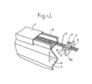
- the upper beam comprising two parts is referenced by 1 and 2.
- the external beam 1 consists in the known way of aluminium and the inner beam 2 in the known way of plastic.
- the web folded in a zigzag line is referenced by 3.
- the upper end of said web 3 is fastened to the inner beam 2.
- a plastic endstop as shown in the Dutch Patent Application 7307075.
- a plastic endstop is provided having an inlet hole for the cords indicated by 4.
- the locking device according to the invention substituting the known endstop consists of a U-shaped portion having a bottom 5 and upstanding walls 6. Both the bottom 5 and the walls 6 are flat and are perpendicular to each other. At the right hand end a cross-plate 7 is provided in which an aperture 8 for the cords 4 is present.
- a tumbler 9 is arranged being connected pivotably to the legs 6 at its upper end, for example this may be implemented by a thin shaft 10 inserted through holes in the legs 6 and through a through-going hole in the tumbler 9.
- the tumbler 9 fits between the legs 6 and may be moved freely with respect to them.
- the lower edge of the tumbler 9 is slightly spaced from the upper side of the bottom 5. Said distance is smaller than the diameter of the cords 4 for which the locking device is intended. This means that the tumbler 9 inclines with respect to the vertical plane, when cords 4 are at the upper side of the bottom 5.
- This member 14 consists of a rectangular vertical portion 14a and a rectangular horizontal flange 14b, perpendicular to each other.
- the member 14 is preferably made as a unit from stainless steel.
- the vertical portion 14a is slidably received in a slot 15 in the thick cross-plate 7.
- an inlet hole for the cords 4 is provided.
- This inlet hole corresponds completely to the aperture 8 in the cross-plate 7 with a bottom part 8a, inclining upwards to the left, but is turned over 180°. This means that the bottom part 8b of the inlet hole in the portion 14a is inclining upwards to the right.
- the cords 4 are in the valley between the slopes 8a and 8b.
- the cords in fig. 6 are moved to the left, they do not press longer on the slope 8b of the member 14. This member 14 is made free. Moreover, the cords 4 are moving upwards along the slope 8a and swing the tumbler 9 away from the cords 4. The blind can be dropped.
- the U-shaped portion 5, 6 and the cross-plate 7 may be manufactured integrally from plastics material.
Landscapes
- Engineering & Computer Science (AREA)
- Structural Engineering (AREA)
- Architecture (AREA)
- Civil Engineering (AREA)
- Blinds (AREA)
- Curtains And Furnishings For Windows Or Doors (AREA)
- Materials Applied To Surfaces To Minimize Adherence Of Mist Or Water (AREA)
- Agricultural Chemicals And Associated Chemicals (AREA)
Claims (2)
Priority Applications (1)
| Application Number | Priority Date | Filing Date | Title |
|---|---|---|---|
| AT81201228T ATE11949T1 (de) | 1980-11-03 | 1981-10-29 | Klemmvorrichtung fuer die zugschnuere von jalousien oder dgl. |
Applications Claiming Priority (4)
| Application Number | Priority Date | Filing Date | Title |
|---|---|---|---|
| NL8006008 | 1980-11-03 | ||
| NL8006008A NL8006008A (nl) | 1980-11-03 | 1980-11-03 | Koordvergrendelinrichting voor een zonwering of dergelijke. |
| US06/235,769 US4443915A (en) | 1980-11-03 | 1981-02-18 | Cord locking device for a sun-blind or the like |
| US235769 | 1981-02-18 |
Publications (2)
| Publication Number | Publication Date |
|---|---|
| EP0051895A1 EP0051895A1 (de) | 1982-05-19 |
| EP0051895B1 true EP0051895B1 (de) | 1985-02-20 |
Family
ID=26645655
Family Applications (1)
| Application Number | Title | Priority Date | Filing Date |
|---|---|---|---|
| EP81201228A Expired EP0051895B1 (de) | 1980-11-03 | 1981-10-29 | Klemmvorrichtung für die Zugschnüre von Jalousien oder dgl. |
Country Status (10)
| Country | Link |
|---|---|
| EP (1) | EP0051895B1 (de) |
| AU (1) | AU548821B2 (de) |
| CA (1) | CA1196264A (de) |
| DE (1) | DE3169088D1 (de) |
| DK (1) | DK157500C (de) |
| ES (1) | ES269988Y (de) |
| GB (1) | GB2086461B (de) |
| MX (1) | MX154133A (de) |
| NO (1) | NO813695L (de) |
| NZ (1) | NZ198830A (de) |
Families Citing this family (2)
| Publication number | Priority date | Publication date | Assignee | Title |
|---|---|---|---|---|
| US6056035A (en) * | 1998-05-18 | 2000-05-02 | Visison By Two Sisters, Inc. | Apparatus and method for hanging shades and curtains |
| GB2379949A (en) * | 2001-09-19 | 2003-03-26 | Ykk Portugal Lda | Cord connector for a blind |
Family Cites Families (7)
| Publication number | Priority date | Publication date | Assignee | Title |
|---|---|---|---|---|
| DE206020C (de) * | ||||
| FR363952A (fr) * | 1906-03-07 | 1906-08-10 | Zenobe Buiret Debeaurain | Arret de corde pour store, imposte, etc. |
| US1964205A (en) * | 1933-06-24 | 1934-06-26 | Ray B Johnson | Shade cord pulley |
| US2547370A (en) * | 1948-11-02 | 1951-04-03 | Charles A Boyer | Rope lock |
| US2731111A (en) * | 1954-12-06 | 1956-01-17 | Lorentzen Hardware Mfg Corp | Cord lock |
| GB1129997A (en) * | 1965-05-12 | 1968-10-09 | Metal Sections Ltd | Locking device for a flexible load-bearing element |
| US4180118A (en) * | 1978-07-13 | 1979-12-25 | Hunter Douglas International N.V. | Cord lock mechanism for venetian blind |
-
1981
- 1981-10-29 DE DE8181201228T patent/DE3169088D1/de not_active Expired
- 1981-10-29 EP EP81201228A patent/EP0051895B1/de not_active Expired
- 1981-11-02 NO NO813695A patent/NO813695L/no unknown
- 1981-11-02 AU AU77029/81A patent/AU548821B2/en not_active Ceased
- 1981-11-02 ES ES1981269988U patent/ES269988Y/es not_active Expired
- 1981-11-02 GB GB8132977A patent/GB2086461B/en not_active Expired
- 1981-11-02 CA CA000389258A patent/CA1196264A/en not_active Expired
- 1981-11-02 NZ NZ198830A patent/NZ198830A/en unknown
- 1981-11-03 MX MX189933A patent/MX154133A/es unknown
- 1981-11-03 DK DK484181A patent/DK157500C/da not_active IP Right Cessation
Also Published As
| Publication number | Publication date |
|---|---|
| MX154133A (es) | 1987-05-25 |
| DK157500B (da) | 1990-01-15 |
| ES269988U (es) | 1983-08-01 |
| AU7702981A (en) | 1982-05-13 |
| NZ198830A (en) | 1984-08-24 |
| GB2086461B (en) | 1984-04-26 |
| CA1196264A (en) | 1985-11-05 |
| AU548821B2 (en) | 1986-01-02 |
| DK157500C (da) | 1990-06-05 |
| NO813695L (no) | 1982-05-04 |
| ES269988Y (es) | 1984-02-16 |
| DK484181A (da) | 1982-05-04 |
| DE3169088D1 (en) | 1985-03-28 |
| GB2086461A (en) | 1982-05-12 |
| EP0051895A1 (de) | 1982-05-19 |
Similar Documents
| Publication | Publication Date | Title |
|---|---|---|
| US5671790A (en) | Screening device for a wall opening | |
| EP0873463B1 (de) | Fensterabdeckung | |
| US6834701B2 (en) | Bottom-up/top-down retractable cellular shade | |
| EP1219776B1 (de) | Leiterbediente Abdeckung mit festen Lamellen für Gebäudeöffnungen | |
| US4443915A (en) | Cord locking device for a sun-blind or the like | |
| US20050022947A1 (en) | Venetian blind | |
| US6339905B1 (en) | Hingeless, parallel storing, sectional aperture covering | |
| WO1997025512A1 (en) | Improved venetian blinds | |
| US6145569A (en) | Arched window blind | |
| US20110108209A1 (en) | Door with retractable screen | |
| AU2004200252A1 (en) | Shutter blind | |
| NL9100871A (nl) | Ophangeenheid voor een zonwering met verticale lamellen. | |
| CA1196264A (en) | Cord locking device for a sun-blind or the like | |
| US6802356B2 (en) | Window blind having a restrainable bottom rail | |
| CA2529118C (en) | Multiple tier venetian blind | |
| EP0242317B1 (de) | Rolladensicherung | |
| US6394170B1 (en) | Operating structure for vertically collecting/shutting a blind | |
| AU722498B3 (en) | A louvre operating mechanism comprising link members, a rack member and a gear member | |
| EP0638704B1 (de) | Schutzvorrichtung gegen das Eindringen von Insekten durch ein Fenster | |
| US5720331A (en) | Vertical multiple-slat blind | |
| US5042552A (en) | Security shutter locking system | |
| RU1779735C (ru) | Жалюзи | |
| FR2555244A1 (fr) | Volet roulant | |
| JP2005016047A (ja) | 雨戸 | |
| CA2293093A1 (fr) | Cadre avec volets coulissants verticalement |
Legal Events
| Date | Code | Title | Description |
|---|---|---|---|
| PUAI | Public reference made under article 153(3) epc to a published international application that has entered the european phase |
Free format text: ORIGINAL CODE: 0009012 |
|
| AK | Designated contracting states |
Designated state(s): AT BE CH DE FR IT LU NL SE |
|
| 17P | Request for examination filed |
Effective date: 19821104 |
|
| ITF | It: translation for a ep patent filed | ||
| GRAA | (expected) grant |
Free format text: ORIGINAL CODE: 0009210 |
|
| AK | Designated contracting states |
Designated state(s): AT BE CH DE FR IT LI LU NL SE |
|
| REF | Corresponds to: |
Ref document number: 11949 Country of ref document: AT Date of ref document: 19850315 Kind code of ref document: T |
|
| REF | Corresponds to: |
Ref document number: 3169088 Country of ref document: DE Date of ref document: 19850328 |
|
| ET | Fr: translation filed | ||
| PLBE | No opposition filed within time limit |
Free format text: ORIGINAL CODE: 0009261 |
|
| STAA | Information on the status of an ep patent application or granted ep patent |
Free format text: STATUS: NO OPPOSITION FILED WITHIN TIME LIMIT |
|
| 26N | No opposition filed | ||
| ITTA | It: last paid annual fee | ||
| PGFP | Annual fee paid to national office [announced via postgrant information from national office to epo] |
Ref country code: FR Payment date: 19921005 Year of fee payment: 12 |
|
| PGFP | Annual fee paid to national office [announced via postgrant information from national office to epo] |
Ref country code: SE Payment date: 19921014 Year of fee payment: 12 Ref country code: AT Payment date: 19921014 Year of fee payment: 12 |
|
| PGFP | Annual fee paid to national office [announced via postgrant information from national office to epo] |
Ref country code: CH Payment date: 19921026 Year of fee payment: 12 |
|
| PGFP | Annual fee paid to national office [announced via postgrant information from national office to epo] |
Ref country code: NL Payment date: 19921031 Year of fee payment: 12 |
|
| PGFP | Annual fee paid to national office [announced via postgrant information from national office to epo] |
Ref country code: LU Payment date: 19921103 Year of fee payment: 12 |
|
| PGFP | Annual fee paid to national office [announced via postgrant information from national office to epo] |
Ref country code: DE Payment date: 19921110 Year of fee payment: 12 |
|
| PGFP | Annual fee paid to national office [announced via postgrant information from national office to epo] |
Ref country code: BE Payment date: 19921116 Year of fee payment: 12 |
|
| EPTA | Lu: last paid annual fee | ||
| PG25 | Lapsed in a contracting state [announced via postgrant information from national office to epo] |
Ref country code: LU Free format text: LAPSE BECAUSE OF NON-PAYMENT OF DUE FEES Effective date: 19931029 Ref country code: AT Effective date: 19931029 |
|
| PG25 | Lapsed in a contracting state [announced via postgrant information from national office to epo] |
Ref country code: SE Effective date: 19931030 |
|
| PG25 | Lapsed in a contracting state [announced via postgrant information from national office to epo] |
Ref country code: LI Effective date: 19931031 Ref country code: CH Effective date: 19931031 Ref country code: BE Effective date: 19931031 |
|
| BERE | Be: lapsed |
Owner name: VEROSOL B.V. Effective date: 19931031 |
|
| PG25 | Lapsed in a contracting state [announced via postgrant information from national office to epo] |
Ref country code: NL Effective date: 19940501 |
|
| NLV4 | Nl: lapsed or anulled due to non-payment of the annual fee | ||
| PG25 | Lapsed in a contracting state [announced via postgrant information from national office to epo] |
Ref country code: FR Effective date: 19940630 |
|
| REG | Reference to a national code |
Ref country code: CH Ref legal event code: PL |
|
| PG25 | Lapsed in a contracting state [announced via postgrant information from national office to epo] |
Ref country code: DE Effective date: 19940701 |
|
| REG | Reference to a national code |
Ref country code: FR Ref legal event code: ST |
|
| EUG | Se: european patent has lapsed |
Ref document number: 81201228.4 Effective date: 19940510 |