EP0051912A1 - Dispositif pour la mesure de la géométrie intérieure des tuyaux - Google Patents
Dispositif pour la mesure de la géométrie intérieure des tuyaux Download PDFInfo
- Publication number
- EP0051912A1 EP0051912A1 EP81303634A EP81303634A EP0051912A1 EP 0051912 A1 EP0051912 A1 EP 0051912A1 EP 81303634 A EP81303634 A EP 81303634A EP 81303634 A EP81303634 A EP 81303634A EP 0051912 A1 EP0051912 A1 EP 0051912A1
- Authority
- EP
- European Patent Office
- Prior art keywords
- pipe
- tube
- internal surface
- monitoring
- carrier member
- Prior art date
- Legal status (The legal status is an assumption and is not a legal conclusion. Google has not performed a legal analysis and makes no representation as to the accuracy of the status listed.)
- Granted
Links
- 238000012544 monitoring process Methods 0.000 title claims abstract description 13
- 238000012876 topography Methods 0.000 title claims description 12
- 238000005259 measurement Methods 0.000 claims description 10
- 238000000034 method Methods 0.000 claims description 7
- 230000001419 dependent effect Effects 0.000 claims description 2
- 239000000523 sample Substances 0.000 description 27
- 238000007689 inspection Methods 0.000 description 9
- 238000012545 processing Methods 0.000 description 5
- 238000010586 diagram Methods 0.000 description 4
- 238000004804 winding Methods 0.000 description 3
- 238000004458 analytical method Methods 0.000 description 2
- 230000000694 effects Effects 0.000 description 2
- 239000012530 fluid Substances 0.000 description 2
- 230000035945 sensitivity Effects 0.000 description 2
- 229910000831 Steel Inorganic materials 0.000 description 1
- 239000011324 bead Substances 0.000 description 1
- 238000006073 displacement reaction Methods 0.000 description 1
- 238000005070 sampling Methods 0.000 description 1
- 239000010959 steel Substances 0.000 description 1
- 230000001360 synchronised effect Effects 0.000 description 1
- 238000012360 testing method Methods 0.000 description 1
- 238000011179 visual inspection Methods 0.000 description 1
- XLYOFNOQVPJJNP-UHFFFAOYSA-N water Substances O XLYOFNOQVPJJNP-UHFFFAOYSA-N 0.000 description 1
Images


Classifications
-
- G—PHYSICS
- G01—MEASURING; TESTING
- G01B—MEASURING LENGTH, THICKNESS OR SIMILAR LINEAR DIMENSIONS; MEASURING ANGLES; MEASURING AREAS; MEASURING IRREGULARITIES OF SURFACES OR CONTOURS
- G01B7/00—Measuring arrangements characterised by the use of electric or magnetic techniques
- G01B7/12—Measuring arrangements characterised by the use of electric or magnetic techniques for measuring diameters
- G01B7/13—Internal diameters
-
- G—PHYSICS
- G01—MEASURING; TESTING
- G01B—MEASURING LENGTH, THICKNESS OR SIMILAR LINEAR DIMENSIONS; MEASURING ANGLES; MEASURING AREAS; MEASURING IRREGULARITIES OF SURFACES OR CONTOURS
- G01B7/00—Measuring arrangements characterised by the use of electric or magnetic techniques
- G01B7/28—Measuring arrangements characterised by the use of electric or magnetic techniques for measuring contours or curvatures
- G01B7/287—Measuring arrangements characterised by the use of electric or magnetic techniques for measuring contours or curvatures using a plurality of fixed, simultaneously operating transducers
Definitions
- This invention relates to apparatus for monitoring the internal surface topography of tubes or pipes, and to inspection methods using such apparatus. It finds particular application in the inspection of pipelines for the transport of fluids.
- Pipelines for the transport of fluids are frequently buried beneath the ground or are submerged under water. Because there are usually large distances between access points, it is not feasible to carry out a visual inspection of the state of the internal surface and other means must be employed. In such cases it is usual to drive a vehicle, known as a pig, carrying inspection devices through the pipeline. Output signals from the inspection devices may be stored in an onboard memory device such as a magnetic tape recorder or transmitted directly by radio or cable to a remote data processor.
- a vehicle known as a pig
- Output signals from the inspection devices may be stored in an onboard memory device such as a magnetic tape recorder or transmitted directly by radio or cable to a remote data processor.
- One such inspection pig is described in our U.K. Patent Application No. 3189/77 which discloses a probe system which measures magnetic field strength as the pig passes down the pipeline. The measurements are subsequently used to monitor variations in the surface profile.
- U.K. Patent No. 1,299,321 U.S. Patent 3,755,908
- This pig has a flexible cup which bears against the surface of the pipeline.
- the body of the pig carries a number of radial, pivotally mounted feeler arms, the free ends of which bear against the periphery of the flexible cup.
- Transducers are coupled to these feeler arms and their output signals provide an indication of the displacement of the feeler arms when the cup is distorted by variations in. the topography as the pig traverses the pipeline.
- this arrangement obviates wear on the feeler arms, it suffers from the disadvantage that the curvature of the cup adjacent the ends of the probe arm is low and hence the system is insensitive to rapid variations in surface profile. Furthermore, the curvature (and hence the sensitivity) varies as the cup flexes.
- the present invention provides apparatus for monitoring the topography of the internal surface of a tube or pipe comprising a body or carrier member, drive means for driving the body or carrier member axially through the tube or pipe, a plurality of sensor means mounted on said body or carrier member successively to monitor a corresponding plurality of points of intersection of said internal surface with a reference plane which is fixed with respect to the principal axis of said body or carrier member as said body or carrier member moves through said pipe or tube, recording means coupled to said sensor means successively to store data dependent on the instantaneous output signals from said sensor means and threshold detector means coupled to at least one of said plurality of sensor means to pass a signal to said recording means when the or one of the sensor means connected thereto exceeds a predetermined value.
- the invention provides a method of monitoring the topography of the internal surface of a tube of pipeline comprising causing a body or carrier member having mounted thereon or attached thereto a plurality of sensor means to traverse said tube or pipeline, successively measuring with said sensor means the points of intersection of said internal surface with a reference plane which is fixed with respect to the principal'axis of said body or carrier member, monitoring the departure from a predetermined value of the measurements and recording the output of said sensor means together with an indication of the incidence of departures of the measurements from the predetermined value.
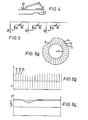
- an inspection pig has a narrow body 1 capable of passing obstacles such as dents or weld beads in a pipeline. It is held in position and driven by conventional flexible cups 2,3, and carries a transducer mounting ring 4 on which is mounted a plurality (typically at least 24, but possibly 60 or more) of probe arms 5. The probe arms are pivoted at the mounted ring and the free ends 6 bear against the internal surface 7 of the pipeline as it is traversed by the pig.
- a probe arm of length r carries a magnetic sensing coil 8 which pivots with the probe in a field created by bias coil windings 10,11.
- the mounting arrangement for the probe transducers ( Figure 3) comprises a pair of blocks 14 adjacent a motion limiting stop 15.
- the end of the probe mounted by pivots 16 on the blocks comprises a carrier 17 for the sense coil 8.
- the probe tip is urged in contact with the pipeline surface by a bias spring 18 engaging an eye 19 on the carrier 17.
- the field generating windings 10,11 are mounted on a steel collar 20 on the body 1 of the pig. An alternating field of frequency lkHz in convenient to generate and detect.
- the surface follower tip 21 of the probe arm 5_ has a relatively large radius (say 10mm). This reduces drift due to probe tip wear during a run and also reduces the sensitivity to small surface features 22, as is indicated by the corresponding transducer output signal 23. (Since the signal from an "event” is spread by this means, the sampling rate can be reduced and the amount of data to be recorded is less).
- a small wheel or roller may be mounted on the end of the probe to achieve the same effect.
- the pickup coils 24 ( Figure 5) are fed with a signal V A in antiphase to the signal applied to the windings 10,11 of the drive coil.
- the magnitude of this signal is adjusted by means of potentiometers 25 to provide an offset equal too the nominal spacing of the pipeline surface and the reference cylinder. This ensures that the output signals represent departures from normality and provides better utilisation of the dynamic range of the recording arrangements.
- Individual 10 coils are trimmed with trimmer resistors 26.
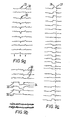
- FIG. 6a An example of a typical group of probe measurements x 1 , x 2 etc. is depicted in Figures 6a and 6b with the corresponding output voltages V reduced by the offset V o shown in Figure 6c: In this example the effect of a dent 9 in the pipeline 15 is shown.
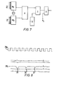
- the signals from the probe transducers are fed to the inputs 27 of a pair of multiplexers Ma,Mb ( Figure 7) which are switched by a clock C so that the outputs at any given instant are those of diametrically opposite probes.
- the outputs are fed to an adder A whose output is an indication of the diameter at that orientation.
- This diameter signal is fed to a differential amplifier D, the other input of which is fed from a voltage source S which generates a voltage equivalent to the average diameter of the pipe.
- the output from the differential amplifier is fed to a comparator circuit E which generates an output if the departure from nominal diameter exceeds a predetermined threshold, and is utilised in the subsequent data processing circuits to flag significant data and thereby reduce the time required to analyse data retrieved from an inspection run.
- the departure from nominal diameter by more than the predetermined value is referred to as a significant non-roundness event (SNORE).
- the SNORE signal When processing data; the SNORE signal is used as a selection flag and readings are taken from the tape for a sufficient distance to display the event which caused the generation of the SNORE signal. Conveniently, the SNORE signal is monitored when the tape is rewound at the end of a measuring run. The SNORE signal is used as a trigger to cause the tape to run forward at normal replay speed for a few seconds whilst the relevant data are read out.
- more than one threshold level may be set and SNORE signals corresponding to each threshold recorded.
- a signal of -lV was set for a threshold of +3.8mm and a signal of +1V for a threshold of +7.6mm.
- a square wave signal 28a on one channel records the distance travelled by the pig whilst another channel 28b depicts the traces 29,30,31 corresponding to depressions of 7.4 mm, 3.7mm and 2.2mm.
- FIGS 9a and 9b illustrate signals 32 due to pig bounce when it hits an obstruction, and obstruction signals caused by an outgoing 33 and an ingoing 34 stick movement.
- Figure 9c shows the traces 35 when the probes strike an eccentrc flange ring 36 ( Figure 10). Sinusoidally varying signals 37 due to pig bounce are also displayed.
- analogue outputs 38 ( Figure 11) from the 24 data channels can be fed to a multiplexer 39 which is coupled by an analogue/digital converter 40 to a data store 41.
- An oscillator 42 synchronised with the multiplexer clock signals fed through a frequency divider 43 gives a sinusoidal output which is fed to an oscilloscope to display a reference circle with which the data signals may be compared.
- tandem pig arrangement as shown in Figure 12 may have a first pig 45 carrying a single bank 46 of probes to monitor profile coupled to a second pig 47 having three banks 48,49,50 of probes to monitor pipeline curvature.
Landscapes
- Physics & Mathematics (AREA)
- General Physics & Mathematics (AREA)
- Investigating Or Analyzing Materials By The Use Of Magnetic Means (AREA)
- Investigating Or Analyzing Materials By The Use Of Ultrasonic Waves (AREA)
- Pipeline Systems (AREA)
- Rigid Pipes And Flexible Pipes (AREA)
- Measurement Of Length, Angles, Or The Like Using Electric Or Magnetic Means (AREA)
- A Measuring Device Byusing Mechanical Method (AREA)
- Length Measuring Devices With Unspecified Measuring Means (AREA)
Applications Claiming Priority (2)
| Application Number | Priority Date | Filing Date | Title |
|---|---|---|---|
| GB8036116A GB2088059B (en) | 1980-11-11 | 1980-11-11 | Pig monitors internal surface of pipeline |
| GB8036116 | 1980-11-11 |
Publications (2)
| Publication Number | Publication Date |
|---|---|
| EP0051912A1 true EP0051912A1 (fr) | 1982-05-19 |
| EP0051912B1 EP0051912B1 (fr) | 1986-03-26 |
Family
ID=10517211
Family Applications (1)
| Application Number | Title | Priority Date | Filing Date |
|---|---|---|---|
| EP81303634A Expired EP0051912B1 (fr) | 1980-11-11 | 1981-08-10 | Dispositif pour la mesure de la géométrie intérieure des tuyaux |
Country Status (9)
| Country | Link |
|---|---|
| US (1) | US4443948A (fr) |
| EP (1) | EP0051912B1 (fr) |
| JP (1) | JPS5788310A (fr) |
| AU (1) | AU530003B2 (fr) |
| CA (1) | CA1166002A (fr) |
| DE (1) | DE3174184D1 (fr) |
| GB (1) | GB2088059B (fr) |
| NO (1) | NO157313C (fr) |
| ZA (1) | ZA815628B (fr) |
Cited By (7)
| Publication number | Priority date | Publication date | Assignee | Title |
|---|---|---|---|---|
| FR2566114A1 (fr) * | 1984-06-15 | 1985-12-20 | Gearhart Ind Inc | Appareil de palpage a transducteurs pour mesure des dimensions internes d'une enveloppe, notamment d'un tube |
| WO1995003526A1 (fr) * | 1993-07-20 | 1995-02-02 | Commonwealth Scientific And Industrial Research Organisation | Systeme d'inspection d'un conduit |
| EP0644398A1 (fr) * | 1993-06-18 | 1995-03-22 | Computalog Usa, Inc. | La mesure de dimensions internes d'un tube dans un puits |
| WO1996013699A3 (fr) * | 1994-10-27 | 1996-06-27 | I D Measurements Inc | Piston d'inspection de tuyauteries et son procede d'utilisation |
| WO2007020438A3 (fr) * | 2005-08-18 | 2007-04-05 | Profile Internat Ltd | Piston racleur pour controle interne de conduites |
| WO2011064603A1 (fr) * | 2009-11-30 | 2011-06-03 | Pipeline Innovations Limited | Racleur mousse instrumenté amélioré |
| EP1887311A3 (fr) * | 2006-08-12 | 2013-11-13 | Ulrich Breitmeier | Procédé destiné à mesurer la microstructure de surfaces de trous cylindriques et dispositif de mesure destiné à la réalisation du procédé de mesure |
Families Citing this family (29)
| Publication number | Priority date | Publication date | Assignee | Title |
|---|---|---|---|---|
| FR2562150B1 (fr) * | 1984-04-03 | 1986-07-04 | Petroles Cie Francaise | Sonde geomecanique pour puits de forage |
| US4754551A (en) * | 1986-05-16 | 1988-07-05 | Spencer Wright Industries, Inc. | Centering gauge tool |
| US4673890A (en) * | 1986-06-18 | 1987-06-16 | Halliburton Company | Well bore measurement tool |
| JPH0263406U (fr) * | 1988-10-31 | 1990-05-11 | ||
| GB2301187B (en) * | 1995-05-22 | 1999-04-21 | British Gas Plc | Method of and apparatus for locating an anomaly in a duct |
| US6857329B2 (en) * | 1998-02-18 | 2005-02-22 | Donsa, Inc. | Pig for detecting an obstruction in a pipeline |
| US6679129B2 (en) | 1998-02-18 | 2004-01-20 | Donsa, Inc. | Pig for detecting an obstruction in a pipeline |
| RU2163369C1 (ru) * | 2000-06-08 | 2001-02-20 | ЗАО "Нефтегазкомплектсервис" | Внутритрубный дефектоскоп |
| RU2164661C1 (ru) * | 2000-06-30 | 2001-03-27 | ЗАО "Нефтегазкомплектсервис" | Внутритрубный многоканальный профилемер |
| CA2443217C (fr) * | 2001-04-02 | 2009-12-22 | Tokyo Gas Co., Ltd. | Methode et dispositif de mesure du diametre interieur d'une canalisation |
| EP1637833B1 (fr) * | 2004-09-20 | 2007-07-18 | Weatherford/Lamb, Inc. | Appareil de mesure de diametre |
| US7936497B2 (en) | 2004-09-27 | 2011-05-03 | Qualcomm Mems Technologies, Inc. | MEMS device having deformable membrane characterized by mechanical persistence |
| US8076928B2 (en) * | 2005-05-13 | 2011-12-13 | Nunally Patrick O'neal | System and method for in-situ integrity and performance monitoring of operating metallic and non-metallic natural gas transmission and delivery pipelines using ultra wideband point-to point and point-to point and point-to-multipoint communication |
| US8336406B2 (en) * | 2007-03-12 | 2012-12-25 | Baker Hughes Incorporated | Protection elements for pipeline investigation devices |
| AU2009263848B2 (en) * | 2008-06-27 | 2014-11-13 | Pii (Canada) Limited | Integrated multi-sensor non-destructive testing |
| US8484858B2 (en) * | 2009-06-17 | 2013-07-16 | Schlumberger Technology Corporation | Wall contact caliper instruments for use in a drill string |
| KR101334351B1 (ko) | 2012-05-31 | 2013-11-29 | 삼성중공업 주식회사 | 배관의 좌굴 감지 장치 |
| RU2516364C1 (ru) * | 2012-12-28 | 2014-05-20 | Открытое Акционерное Общество (ОАО) "Оргэнергогаз" | Комплекс дефектоскопии технологических трубопроводов |
| RU2533754C1 (ru) * | 2013-09-25 | 2014-11-20 | Открытое Акционерное Общество (ОАО) "Оргэнергогаз" | Регулятор скорости перемещения внутритрубных инспектирующих снарядов |
| JP6405614B2 (ja) * | 2013-10-22 | 2018-10-17 | ニプロ株式会社 | 計測装置 |
| JP6304811B2 (ja) * | 2014-03-28 | 2018-04-04 | 芦森工業株式会社 | 管路内径検査装置 |
| GB201406131D0 (en) * | 2014-04-04 | 2014-05-21 | Epidote Holdings Ltd | System and method for determining deformed pipe geometry |
| WO2017221282A1 (fr) * | 2016-06-21 | 2017-12-28 | 川崎重工業株式会社 | Système de mesure de forme de tuyau et système de mise en correspondance de forme de tuyau |
| CN107907095B (zh) * | 2017-11-10 | 2019-08-09 | 中国石油大学(北京) | 管道变形检测清管器 |
| CN108413919B (zh) * | 2018-01-30 | 2020-08-28 | 中国石油大学(北京) | 管道通径检测装置 |
| RU2690973C1 (ru) * | 2018-09-17 | 2019-06-07 | Публичное акционерное общество "Транснефть" (ПАО "Транснефть") | Устройство для измерения внутреннего профиля трубопровода |
| US10767972B1 (en) * | 2020-03-26 | 2020-09-08 | Mark Turnbaugh | Measuring assemblies |
| TWI911233B (zh) * | 2020-06-18 | 2026-01-11 | 泰商榮龍工程設備服務有限公司 | 一用於偵測一表面之不平整度之感測器模組,一具有該模組之裝置,以及一使用該感測器模組,以偵測一表面其不平整度之方法 |
| CN115178544A (zh) * | 2022-05-06 | 2022-10-14 | 西南石油大学 | 一种软骨架智能清管器 |
Citations (5)
| Publication number | Priority date | Publication date | Assignee | Title |
|---|---|---|---|---|
| US3973441A (en) * | 1975-11-12 | 1976-08-10 | Trans Canada Pipelines Limited | Accelerometer pig |
| GB1502830A (en) * | 1974-07-19 | 1978-03-01 | Williamson Inc T | Pipeline pig |
| DE2810552A1 (de) * | 1977-03-10 | 1978-09-14 | Elf Aquitaine | Vorrichtung zur genauen messung einer zylinderflaeche |
| GB2023293A (en) * | 1978-05-20 | 1979-12-28 | Gkn Group Services Ltd | Determining path of pipe |
| GB1586581A (en) * | 1977-01-26 | 1981-03-18 | British Gas Corp | Pipeline inspection equipment |
Family Cites Families (13)
| Publication number | Priority date | Publication date | Assignee | Title |
|---|---|---|---|---|
| BE566226A (fr) * | ||||
| US2497990A (en) * | 1946-11-30 | 1950-02-21 | Standard Oil Dev Co | Apparatus for logging boreholes |
| US2649786A (en) * | 1948-04-01 | 1953-08-25 | Eastman Oil Well Survey Co | Well bore caliper having linear electrical response |
| US2815578A (en) * | 1956-12-10 | 1957-12-10 | Shell Dev | Well bore calipering and telemetering system |
| US2908085A (en) * | 1957-11-15 | 1959-10-13 | Tuboscope Company | Measuring instruments |
| US3755908A (en) * | 1971-01-13 | 1973-09-04 | Williamson Inc T | Pipeline pig |
| SU438777A1 (ru) * | 1973-03-26 | 1974-08-05 | Всесоюзный научно-исследовательский институт нефтепромысловой геофизики | Скважинный профилеметр |
| IT998126B (it) * | 1973-06-04 | 1976-01-20 | Snam Progetti | Dispositivo per il rilievo in con tinuo della ovalizzazione e delle proiezioni su due piani ortogonali della deformata di tubazioni som merse |
| JPS5246102U (fr) * | 1975-09-30 | 1977-04-01 | ||
| JPS5386368A (en) * | 1977-01-05 | 1978-07-29 | Takeda Chemical Industries Ltd | Method for producing solids containing oganic matters |
| JPS549658A (en) * | 1977-06-23 | 1979-01-24 | Ouyou Chishitsu Chiyousa Jimus | Large aperture caliber |
| JPS5527974A (en) * | 1978-08-21 | 1980-02-28 | Igarashi Kogyo Kk | Space factor checker for underground pipe |
| JPS5756681A (en) * | 1980-09-24 | 1982-04-05 | Hitachi Ltd | Swash plate type compressor |
-
1980
- 1980-11-11 GB GB8036116A patent/GB2088059B/en not_active Expired
-
1981
- 1981-08-10 DE DE8181303634T patent/DE3174184D1/de not_active Expired
- 1981-08-10 EP EP81303634A patent/EP0051912B1/fr not_active Expired
- 1981-08-14 ZA ZA815628A patent/ZA815628B/xx unknown
- 1981-08-14 NO NO812763A patent/NO157313C/no unknown
- 1981-08-24 JP JP56132558A patent/JPS5788310A/ja active Pending
- 1981-08-25 CA CA000384533A patent/CA1166002A/fr not_active Expired
- 1981-09-23 US US06/304,958 patent/US4443948A/en not_active Expired - Lifetime
- 1981-10-02 AU AU75981/81A patent/AU530003B2/en not_active Ceased
Patent Citations (5)
| Publication number | Priority date | Publication date | Assignee | Title |
|---|---|---|---|---|
| GB1502830A (en) * | 1974-07-19 | 1978-03-01 | Williamson Inc T | Pipeline pig |
| US3973441A (en) * | 1975-11-12 | 1976-08-10 | Trans Canada Pipelines Limited | Accelerometer pig |
| GB1586581A (en) * | 1977-01-26 | 1981-03-18 | British Gas Corp | Pipeline inspection equipment |
| DE2810552A1 (de) * | 1977-03-10 | 1978-09-14 | Elf Aquitaine | Vorrichtung zur genauen messung einer zylinderflaeche |
| GB2023293A (en) * | 1978-05-20 | 1979-12-28 | Gkn Group Services Ltd | Determining path of pipe |
Cited By (8)
| Publication number | Priority date | Publication date | Assignee | Title |
|---|---|---|---|---|
| FR2566114A1 (fr) * | 1984-06-15 | 1985-12-20 | Gearhart Ind Inc | Appareil de palpage a transducteurs pour mesure des dimensions internes d'une enveloppe, notamment d'un tube |
| EP0644398A1 (fr) * | 1993-06-18 | 1995-03-22 | Computalog Usa, Inc. | La mesure de dimensions internes d'un tube dans un puits |
| WO1995003526A1 (fr) * | 1993-07-20 | 1995-02-02 | Commonwealth Scientific And Industrial Research Organisation | Systeme d'inspection d'un conduit |
| WO1996013699A3 (fr) * | 1994-10-27 | 1996-06-27 | I D Measurements Inc | Piston d'inspection de tuyauteries et son procede d'utilisation |
| WO2007020438A3 (fr) * | 2005-08-18 | 2007-04-05 | Profile Internat Ltd | Piston racleur pour controle interne de conduites |
| EP1887311A3 (fr) * | 2006-08-12 | 2013-11-13 | Ulrich Breitmeier | Procédé destiné à mesurer la microstructure de surfaces de trous cylindriques et dispositif de mesure destiné à la réalisation du procédé de mesure |
| WO2011064603A1 (fr) * | 2009-11-30 | 2011-06-03 | Pipeline Innovations Limited | Racleur mousse instrumenté amélioré |
| US8925400B2 (en) | 2009-11-30 | 2015-01-06 | Pipeline Innovations Limited | Instrumented foam pig |
Also Published As
| Publication number | Publication date |
|---|---|
| JPS5788310A (en) | 1982-06-02 |
| NO812763L (no) | 1982-05-12 |
| GB2088059B (en) | 1985-02-06 |
| CA1166002A (fr) | 1984-04-24 |
| GB2088059A (en) | 1982-06-03 |
| US4443948A (en) | 1984-04-24 |
| EP0051912B1 (fr) | 1986-03-26 |
| AU7598181A (en) | 1982-05-20 |
| AU530003B2 (en) | 1983-06-30 |
| NO157313B (no) | 1987-11-16 |
| NO157313C (no) | 1988-02-24 |
| DE3174184D1 (en) | 1986-04-30 |
| ZA815628B (en) | 1982-09-29 |
Similar Documents
| Publication | Publication Date | Title |
|---|---|---|
| US4443948A (en) | Internal geometry tool | |
| FI74152B (fi) | Portabel anordning foer ultraljudsinspektion pao ett roerformigt objekt. | |
| US5156636A (en) | Ultrasonic method and apparatus for measuring outside diameter and wall thickness of a tube and having temperature compensation | |
| US4567747A (en) | Self-calibration system for ultrasonic inspection apparatus | |
| US4046536A (en) | Monitoring and control of optical fiber diameters | |
| CA1108743A (fr) | Methode et dispositif ultrasonique de detection de defauts | |
| GB2107063A (en) | Fixing geographical reference of pipeline pigs in pipelines | |
| US4541278A (en) | Pipeline corrosion sensing device and method | |
| US4270389A (en) | Method and apparatus for the automatic ultrasonic flaw detection | |
| US6641535B2 (en) | Ultrasonic probe, in particular for manual inspections | |
| RU2157514C1 (ru) | Способ и устройство для технического диагностирования магистрального трубопровода | |
| JP3635490B2 (ja) | 管体のプロファイル測定方法及び装置、並びに管体の応力測定方法 | |
| EP0554958B1 (fr) | Méthode et appareil pour l'inspection des tubes | |
| US4545249A (en) | Acoustical position gage | |
| CA1189944A (fr) | Dispositif de diagraphie | |
| RU2106569C1 (ru) | Устройство для контроля профиля внутренней поверхности, пространственного положения и напряженного состояния трубопровода | |
| RU2172488C1 (ru) | Снаряд-дефектоскоп для контроля отверстий в стенках внутри трубопровода | |
| US4575829A (en) | Method and apparatus for sound level determination | |
| JP4118487B2 (ja) | 鋼管の腐食診断方法 | |
| JP2001349846A (ja) | 管内検査装置の円周方向角度検出方法 | |
| KR100983674B1 (ko) | 초음파 탐촉자의 입사점 및 굴절각 자동 측정장치 | |
| RU12734U1 (ru) | Устройство для неразрушающего контроля трубопроводов | |
| RU2772550C1 (ru) | Многоканальная измерительная система для измерения геометрического профиля трубопровода | |
| RU2606205C1 (ru) | Внутритрубный снаряд-дефектоскоп | |
| JP2005049360A (ja) | 管体の断面形状測定装置 |
Legal Events
| Date | Code | Title | Description |
|---|---|---|---|
| PUAI | Public reference made under article 153(3) epc to a published international application that has entered the european phase |
Free format text: ORIGINAL CODE: 0009012 |
|
| AK | Designated contracting states |
Designated state(s): BE DE FR IT NL |
|
| 17P | Request for examination filed |
Effective date: 19820419 |
|
| GRAA | (expected) grant |
Free format text: ORIGINAL CODE: 0009210 |
|
| AK | Designated contracting states |
Kind code of ref document: B1 Designated state(s): BE DE FR IT NL |
|
| ITF | It: translation for a ep patent filed | ||
| REF | Corresponds to: |
Ref document number: 3174184 Country of ref document: DE Date of ref document: 19860430 |
|
| ET | Fr: translation filed | ||
| BECH | Be: change of holder |
Free format text: 860326 *BRITISH GAS P.L.C. |
|
| PLBE | No opposition filed within time limit |
Free format text: ORIGINAL CODE: 0009261 |
|
| STAA | Information on the status of an ep patent application or granted ep patent |
Free format text: STATUS: NO OPPOSITION FILED WITHIN TIME LIMIT |
|
| 26N | No opposition filed | ||
| NLS | Nl: assignments of ep-patents |
Owner name: BRITISH GAS PLC TE LONDEN, GROOT-BRITTANNIE. |
|
| REG | Reference to a national code |
Ref country code: FR Ref legal event code: TP |
|
| ITTA | It: last paid annual fee | ||
| PGFP | Annual fee paid to national office [announced via postgrant information from national office to epo] |
Ref country code: FR Payment date: 19970710 Year of fee payment: 17 |
|
| PGFP | Annual fee paid to national office [announced via postgrant information from national office to epo] |
Ref country code: BE Payment date: 19970715 Year of fee payment: 17 |
|
| PGFP | Annual fee paid to national office [announced via postgrant information from national office to epo] |
Ref country code: DE Payment date: 19970723 Year of fee payment: 17 |
|
| PGFP | Annual fee paid to national office [announced via postgrant information from national office to epo] |
Ref country code: NL Payment date: 19970724 Year of fee payment: 17 |
|
| PG25 | Lapsed in a contracting state [announced via postgrant information from national office to epo] |
Ref country code: BE Free format text: LAPSE BECAUSE OF NON-PAYMENT OF DUE FEES Effective date: 19980831 |
|
| REG | Reference to a national code |
Ref country code: FR Ref legal event code: TP |
|
| BERE | Be: lapsed |
Owner name: BRITISH GAS P.L.C. Effective date: 19980831 |
|
| PG25 | Lapsed in a contracting state [announced via postgrant information from national office to epo] |
Ref country code: NL Free format text: LAPSE BECAUSE OF NON-PAYMENT OF DUE FEES Effective date: 19990301 |
|
| PG25 | Lapsed in a contracting state [announced via postgrant information from national office to epo] |
Ref country code: FR Free format text: LAPSE BECAUSE OF NON-PAYMENT OF DUE FEES Effective date: 19990430 |
|
| NLV4 | Nl: lapsed or anulled due to non-payment of the annual fee |
Effective date: 19990301 |
|
| PG25 | Lapsed in a contracting state [announced via postgrant information from national office to epo] |
Ref country code: DE Free format text: LAPSE BECAUSE OF NON-PAYMENT OF DUE FEES Effective date: 19990601 |
|
| REG | Reference to a national code |
Ref country code: FR Ref legal event code: ST |