EP0051916A1 - Prospection sismique au moyen d'un système de transmission d'énergie et d'enregistrement en continu - Google Patents
Prospection sismique au moyen d'un système de transmission d'énergie et d'enregistrement en continu Download PDFInfo
- Publication number
- EP0051916A1 EP0051916A1 EP81304346A EP81304346A EP0051916A1 EP 0051916 A1 EP0051916 A1 EP 0051916A1 EP 81304346 A EP81304346 A EP 81304346A EP 81304346 A EP81304346 A EP 81304346A EP 0051916 A1 EP0051916 A1 EP 0051916A1
- Authority
- EP
- European Patent Office
- Prior art keywords
- energy
- earth
- seismic
- frequency
- frequencies
- Prior art date
- Legal status (The legal status is an assumption and is not a legal conclusion. Google has not performed a legal analysis and makes no representation as to the accuracy of the status listed.)
- Granted
Links
- 238000000034 method Methods 0.000 claims abstract description 36
- 238000001228 spectrum Methods 0.000 claims description 31
- 238000010304 firing Methods 0.000 claims description 22
- 230000000737 periodic effect Effects 0.000 claims description 8
- 230000001902 propagating effect Effects 0.000 claims 3
- 230000000903 blocking effect Effects 0.000 claims 1
- 238000006243 chemical reaction Methods 0.000 abstract 1
- 230000003595 spectral effect Effects 0.000 description 9
- 230000000717 retained effect Effects 0.000 description 4
- 238000005070 sampling Methods 0.000 description 4
- 239000000463 material Substances 0.000 description 3
- 230000000063 preceeding effect Effects 0.000 description 2
- XLYOFNOQVPJJNP-UHFFFAOYSA-N water Substances O XLYOFNOQVPJJNP-UHFFFAOYSA-N 0.000 description 2
- 238000004891 communication Methods 0.000 description 1
- 238000005056 compaction Methods 0.000 description 1
- 230000001419 dependent effect Effects 0.000 description 1
- 238000010586 diagram Methods 0.000 description 1
- 230000000694 effects Effects 0.000 description 1
- 230000005284 excitation Effects 0.000 description 1
- 230000007274 generation of a signal involved in cell-cell signaling Effects 0.000 description 1
- 230000010354 integration Effects 0.000 description 1
- 238000007781 pre-processing Methods 0.000 description 1
- 230000008569 process Effects 0.000 description 1
- 230000009467 reduction Effects 0.000 description 1
- 238000000926 separation method Methods 0.000 description 1
- 239000011343 solid material Substances 0.000 description 1
- 238000010408 sweeping Methods 0.000 description 1
- 230000009466 transformation Effects 0.000 description 1
- 230000001131 transforming effect Effects 0.000 description 1
- 230000032258 transport Effects 0.000 description 1
Images

Classifications
-
- G—PHYSICS
- G01—MEASURING; TESTING
- G01V—GEOPHYSICS; GRAVITATIONAL MEASUREMENTS; DETECTING MASSES OR OBJECTS; TAGS
- G01V1/00—Seismology; Seismic or acoustic prospecting or detecting
- G01V1/003—Seismic data acquisition in general, e.g. survey design
- G01V1/005—Seismic data acquisition in general, e.g. survey design with exploration systems emitting special signals, e.g. frequency swept signals, pulse sequences or slip sweep arrangements
-
- G—PHYSICS
- G01—MEASURING; TESTING
- G01V—GEOPHYSICS; GRAVITATIONAL MEASUREMENTS; DETECTING MASSES OR OBJECTS; TAGS
- G01V1/00—Seismology; Seismic or acoustic prospecting or detecting
- G01V1/24—Recording seismic data
- G01V1/247—Digital recording of seismic data, e.g. in acquisition units or nodes
Definitions
- This invention relates generally to methods for seismic prospecting and more specifically to a method which optimizes the use of the energy available from a seismic source.
- acoustic energy is introduced into the earth at or near its surface by one of a variety of acoustic sources.
- Typical sources in a land prospecting environment include dynamite and vibrators.
- marine prospecting it is customary to use air guns.
- an array of seismic receivers is arranged in the vicinity of the source.
- this typically comprises a plurality of geophone groups arranged along a line extending from the source point, or in some cases in an areal distribution near the source point.
- the seismic receivers typically comprise a plurality of hydrophones towed behind the boat in a seismic streamer.
- the energy When the source is fired, the energy propagates down through the material of the earth in the form of elastic waves. These waves are reflected by impedance discontinuities that occur at the boundary between layers of different subsurface materials. The reflected energy propagates back upward and is detected by the seismic receivers. Examination of the received signals by skilled analysts permits judgments to be made about the subsurface structure.
- the data from the seismic receivers is recorded for a sufficient period of time T to ensure that all reflections from the deepest reflector of interest are included in the record. Recording is then discontinued until the next source excitation is to occur. As a result there is no intermingling of reflections from two or more shots on any given record.
- the sources are fired at intervals of ten seconds or more.
- processing and interpretation of the signals received by the receivers is performed in the time, domain. It is also possible, however, to transform the signals and perform the processing in the frequency domain.
- DFT discrete fourier transform
- the frequency interval Af between the plurality of discrete frequencies at which independent data exists is determined by the recording time T max' Specifically
- Typical seismic sources such as those enumerated above introduce energy into the earth over a relatively broad band of frequencies.
- the received signals contain energy at the DFT frequencies which are discarded as well as at those frequencies that are retained for further processing.
- Collection of the data in accordance with the principles of this invention effectively overcomes this problem.
- the data is collected in such a way as to ensure that substantially all of the energy introduced by the source occurs at those frequencies which are to be retained for further processing.
- the frequencies at which transformed values are to be retained for further processing are evenly spaced over some range of frequencies.
- the source is then fired in such a way as to ensure that the power density spectrum of the energy introduced into the earth comprises a comb spectrum.
- Such a spectrum has substantial energy only at a plurality of evenly spaced discrete frequencies. This spectrum is chosen so that the discrete frequencies where substantial energy occurs correspond to the transformed frequencies which are to be retained for further processing.
- the comb power density spectrum is achieved by repeatedly firing the source at a constant repetition rate and continuously recording the data from the receivers. In this manner, the received signal at any point in time will include reflected energy from a plurality of the preceeding source firings. A typical interval between successive source firings is one second.
- Vibrators typically generate continuous signals that are sinusoidal in form.
- the instantaneous frequency of the sine wave signals is controllable and is typically caused to vary through a linear sweep.
- the instantaneous vibrator frequency is frequency modulated by a second sine wave frequency. In this way, the vibrator can also be caused to impart energy to the earth having a comb spectrum.
- a prospecting vessel 10 transports both the seismic source and receivers at or near the surface of the water 12.
- the seismic source 14 typically comprises an air gun or an array of air guns.
- the seismic receivers .comprise a plurality of hydrophones 16 carried by a seismic streamer 18. The length of such streamers is typically of the order of two kilometers.
- Energy from source 14 propagates downward through the water in the form of pressure variations, and enters the solid material of the earth at the seabed 20. The energy continues downward into the earth in the form of elastic waves. If the waves encounter an impedance discontinuity 22 such as the boundary between two layers of subsurface materials having different lithologic properties a portion of the wave is reflected back upward to be detected by the seismic receivers.
- a representative ray path 24 for such energy propagation is illustrated in FIGURE 1.
- Reflections from deep reflectors are received by the seismic receivers later in a record than energy from more shallow reflectors.
- the source was fired once and data was then recorded from the seismic receivers for a sufficient period of time to ensure that reflections from the deepest reflector of interest were included within the record. Recording was then discontinued until the next time that the source was to be fired.
- data from the seismic receivers is recorded continuously.
- the source is fired periodically with a repetition rate substantially exceeding that used with prior art methods. In the past the minimum interval between successive firings of the source was about ten seconds. In the practice of the present invention on the other hand, a one second interval between successive firings is typical.
- FIGURE 2a is an idealized time diagram of the waveform produced by source 14.
- the contribution to the overall waveform produced by each firing of the source is represented by an impulse or Dirac-delta function.
- the source firings occur repetitively with a time interval At between successive source firings.
- the time function produced by source 14 can be represented by an infinite series of impulse functions.
- FIGURE 2b The Fourier transform of the time waveform of FIGURE 2a is illustrated in FIGURE 2b.
- this frequency domain representation of the function also comprises an infinite series of impulse functions.
- the power density spectrum of the waveform of FIGURE 2a has energy only at a plurality of discrete frequencies.
- the spacing between adjacent frequencies where spectral peaks occur corresponds to a frequency difference of Af where:
- This type of power density spectrum is referred to as a comb spectrum.
- FIGURES 2a and 2b While the infinite series of impulse functions illustrated in FIGURES 2a and 2b are useful for certain conceptual purposes, in one sense they depart from the actual physical situation. This results principally from the fact that the mathematical Dirac-delta function assumed for the source waveform is not exactly achievable with physical structures.
- the Dirac-delta function is one whose time duration becomes infinitesmally small and whose amplitude becomes infinitely large.
- the waveforms produced by seismic air guns or other impulsive seismic sources have some short but finite duration and a large but not infinite amplitude. Therefore a more accurate portrayal of the actual time domain function produced by repeated firings of an air gun would be produced by convolving the infinite series of impulse functions of FIGURE 2a with the actual waveform, 7 ' produced by a single firing of the air gun.
- convolution of two such functions in the time domain corresponds to multiplication of the transforms of the two time domain functions in the frequency domain. If one performs the Fourier transform on the typical wavelet produced by a single firing of an air gun, one obtains a transform which has significant values over some range of low frequencies and substantially zero amplitude at frequencies above some cutoff frequency. In other words the Fourier transform of such a time domain function to a certain extent resembles that of a low pass filter. If this type of transform is multiplied with the infinite series of impulse functions of FIGURE 2b, there results a finite series of weighted impulse functions centered around frequency zero and extending from some cutoff frequency down to the negative counterpart of that cutoff frequency.
- the signals received by the hydrophones are digitized and recorded continuously. There are no breaks in recording between shots as is the case in prior art methods. Thus for practical purposes the records from each hydrophone are infinite in extent. However, also for practical reasons, it is necessary to block the data into finite segments for processing. Such data may be sampled at a one millisecond sampling rate and.a typical block length might be eight seconds.
- the segment of sampled data is first converted to the frequency domain using the DFT.
- N is actually chosen to have a value of 8192.
- This particular choice for the number of samples in a segment is.dictated by the fact that the transformation is actually performed using the fast Fourier transform which requires that the number of samples in a segment be equal to some power of two.
- the DFT is defined in equation 1.
- the DFT produces a plurality of transformed values in the frequency domain, each corresponding to a specific value of k.
- the frequency interval ⁇ f between any two adjacent transform values, that is between transform values at two consecutive values of the index k, is given by equation 2.
- the frequency interval 4f has a value of .122 hertz. Therefore, the frequency domain function H(k) resulting from the DFT has a value at each of a plurality of frequencies where these frequencies are separated by intervals of .122 hertz. In the claims, these frequencies at which H(k) has values will be referred to as the frequencies of the DFT.
- the source waveform of FIGURE 2a is assumed to be infinite in duration.
- the data must be processed in blocks, and in this description the blocks have been assumed to be 8192 samples in length.
- the circularity property means that the finite data segment is assumed to be repeated in the Fourier analysis, and since the firing interval At is an integer submultiple of the data block, periodicity is returned in the Fourier transform.
- the actual firing instants may not be possible to control the actual firing instants to the degree that might be desirable.
- the actual power density spectrum may be slightly different than that illustrated in FIGURE 2b and small amounts of energy may occur at frequencies other than those denoted by the inpulse functions.
- the power density spectrum has substantially non-zero values only at certain discrete frequencies.
- all of the source output energy is caused to occur at the frequencies which will be used in subsequent processing.
- a vibratory energy source is used.
- One such source is illustrated in U.S. Patent No. 3,929,206.
- Such vibratory sources are typically hydraulically energized and serve to impart sinusoidal energy to the earth.
- the instantaneous frequency of the imparted signal can be controlled by the vibrator electronics and can be caused to vary in a preselected manner.
- a typical "sweep" or “chirp” waveform is illustrated diagramatically in FIGURE 3. In a typical case such a waveform may begin with an instantaneous frequency of five hertz and sweep linearly up to an instantaneous frequency of 100 hertz over a period of fifteen seconds.
- the instantaneous frequency of the vibrator is varied in a novel and highly advantageous manner so as to result in a comb power density spectrum.
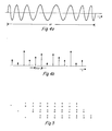
- FIGURES 4a and 4b illustrate such a sweep signal and its frequency domain counterpart when the nature of the periodic variation is sinusoidal.
- the time interval At covers one cycle of the periodic variation.
- the instantaneous frequency is caused to vary over a preselected range of frequencies in a periodic manner.
- the variation in the instantaneous frequency is at a lower frequency than any value of the instantaneous frequency . itself.
- the vibrator can be thought of as having a carrier frequency which is frequency modulated by a low frequency modulating sine wave.
- a frequency modulated signal has the functional representation given in equation 3 below where W and W m are the radian carrier and modulating frequencies respectively, and where k f is the degree of modulation.
- the frequency modulated wave is seen to consist of an infinite series of sinusoids centered about the carrier frequency W o .
- the other sinusoids are separated from the carrier frequency by frequency intervals which are integer multiples of the modulating frequency W m .
- Indivudual sinusoids have amplitudes which are given by the various Bessel functions.
- the frequency modulated signal will cover the entire frequency spectrum with sidebands.
- the Bessel coefficients decrease rather rapidly and the series converges, so that actually the bandwidth that is excited by the vibrator is finite.
- the carrier frequency and the modulating frequency must be chosen so that the spectral peaks of the comb power density spectrum occur at frequencies of the DFT which are to be used.
- record lengths of approximately thirty seconds. If in fact a record of 32.768 seconds is utilized with a sampling rate of 4 milliseconds, then one again obtains a record having 8,192 samples.
- the spacing between adjacent frequencies in the DFT is .0305175 hertz. If one selects every thirty- second such frequency for subsequent processing, the interval between processed frequencies is .97656 hertz.
- One such processed frequency which occurs at about the middle of the band of interest is at 49.804662 hertz.
- the vibrator carrier frequency is selected to be at this frequency then the W o term of the expansion of equation 4 will occur at a processed frequency. Since the other processed frequencies will occur at integral multiples of .97656 hertz from this central frequency, the modulating frequency is selected to be .97656 hertz so that the sidebands of the vibrator signal occur at processed frequencies.
- FIGURE 5 is a diagramatic illustration of two-dimensional roll-a-long exploration.
- the top row of FIGURE 5 illustrates the typical positions of a seismic source such as a vibrator, indicated by an asterisk, and eight geophone groups, indicated by open circles and arbitrarily numbered one through eight.
- a seismic source such as a vibrator, indicated by an asterisk
- eight geophone groups indicated by open circles and arbitrarily numbered one through eight.
- the vibrator is operated as above to produce a periodically frequency modulated waveform as discussed above. While this is taking place, a second vibrator is moved to the location illustrated in the second line of the FIGURE and a geophone group is moved to the head end of the spread.
- the first vibrator is ready to be turned off, the second vibrator is turned on in synchronism with the first vibrator so the net effect is a continuation of the periodically frequency modulated waveform imparted to the earth.
- the first vibrator is moved to the position shown in the third line of FIGURE 5 where it is ready to pick up the sequence of signal generation from the second vibrator.
- the various geophone groups receive and record data continuously except during those intervals when the group is being moved. This continuous recording is characteristic of the preferred embodiment irrespective of the type of source.
- the substantial data compaction provided by this method can be accomplished in the field thereby reducing the amount of data that must be recorded and transported to a processing center.
- the continuously received data is blocked into finite segments for processing such as by the DFT.
- this can be done in the field as follows. As soon as a segment of data is received, it can be transformed using the DFT, the transform values at undesired frequencies discarded, and only the transform values at desired frequencies recorded on the storage medium such as magnetic tape. While this preliminary processing is taking place the geophone group is receiving and storing the next segment of data in temporary storage. As soon as this next segment has been completely received, it too is pre-processed while the group is recording the third segment. This procedure continues as desired so that the pre-processing including the data completion is accomplished virtually in real time with the result that the amount of data which must be recorded for subsequent processing is greatly reduced.
- the comb spectrum has a plurality of regularly spaced spectral peaks, it is not necessary in the practice of the invention for such regular spacing to occur. In other words, some of the teeth of the comb can be missing. In the case of the vibrator embodiment, this variation is very nearly realized since certain of the spectral peaks will have amplitudes substantially below those of other spectral peaks. Thus certain of the spectral peaks in the comb are virtually non-existant.
Landscapes
- Engineering & Computer Science (AREA)
- Remote Sensing (AREA)
- Physics & Mathematics (AREA)
- Life Sciences & Earth Sciences (AREA)
- Geology (AREA)
- Environmental & Geological Engineering (AREA)
- Acoustics & Sound (AREA)
- General Life Sciences & Earth Sciences (AREA)
- General Physics & Mathematics (AREA)
- Geophysics (AREA)
- Geophysics And Detection Of Objects (AREA)
- Buildings Adapted To Withstand Abnormal External Influences (AREA)
- Supporting Of Heads In Record-Carrier Devices (AREA)
Applications Claiming Priority (2)
| Application Number | Priority Date | Filing Date | Title |
|---|---|---|---|
| US193998 | 1980-10-06 | ||
| US06/193,998 US4458339A (en) | 1980-10-06 | 1980-10-06 | Seismic prospecting using a continuous shooting and continuous recording system |
Publications (2)
| Publication Number | Publication Date |
|---|---|
| EP0051916A1 true EP0051916A1 (fr) | 1982-05-19 |
| EP0051916B1 EP0051916B1 (fr) | 1986-04-09 |
Family
ID=22715916
Family Applications (1)
| Application Number | Title | Priority Date | Filing Date |
|---|---|---|---|
| EP81304346A Expired EP0051916B1 (fr) | 1980-10-06 | 1981-09-22 | Prospection sismique au moyen d'un système de transmission d'énergie et d'enregistrement en continu |
Country Status (6)
| Country | Link |
|---|---|
| US (1) | US4458339A (fr) |
| EP (1) | EP0051916B1 (fr) |
| AU (1) | AU544586B2 (fr) |
| CA (1) | CA1180435A (fr) |
| DE (1) | DE3174321D1 (fr) |
| NO (1) | NO156669C (fr) |
Cited By (2)
| Publication number | Priority date | Publication date | Assignee | Title |
|---|---|---|---|---|
| WO2016005784A1 (fr) * | 2014-07-08 | 2016-01-14 | Cgg Services Sa | Système et procédé de reconstruction de données sismiques générées par une émission à spectre de faible densité |
| WO2017179988A1 (fr) | 2015-10-01 | 2017-10-19 | Statoil Petroleum Sa | Procédé et système pour générer des données géophysiques |
Families Citing this family (23)
| Publication number | Priority date | Publication date | Assignee | Title |
|---|---|---|---|---|
| US4598392A (en) * | 1983-07-26 | 1986-07-01 | Mobil Oil Corporation | Vibratory signal sweep seismic prospecting method and apparatus |
| GB2148001A (en) | 1983-10-11 | 1985-05-22 | Shell Int Research | A method and system for controlling the moments of firing of marine seismic sources |
| US4739858A (en) * | 1987-03-02 | 1988-04-26 | Western Atlas International, Inc. | Spectrally-shaped air gun arrays |
| US5545858A (en) * | 1992-06-19 | 1996-08-13 | Sansone; Stanley A. | Method for processing and interpreting wide band FM seismic signals |
| US6181646B1 (en) | 1997-01-07 | 2001-01-30 | Hyroacoustics, Inc. | Geophysical exploration system using seismic vibrator source which provides a composite sweep |
| US6443812B1 (en) * | 1999-08-24 | 2002-09-03 | Rodel Holdings Inc. | Compositions for insulator and metal CMP and methods relating thereto |
| US7561493B2 (en) | 2003-05-30 | 2009-07-14 | Fairfield Industries, Inc. | Method and apparatus for land based seismic data acquisition |
| US7310287B2 (en) | 2003-05-30 | 2007-12-18 | Fairfield Industries Incorporated | Method and apparatus for seismic data acquisition |
| US8534959B2 (en) | 2005-01-17 | 2013-09-17 | Fairfield Industries Incorporated | Method and apparatus for deployment of ocean bottom seismometers |
| US8127706B2 (en) * | 2005-05-02 | 2012-03-06 | Fairfield Industries Incorporated | Deck configuration for ocean bottom seismometer launch platforms |
| US7433265B2 (en) * | 2005-10-04 | 2008-10-07 | Fairfield Industries, Inc. | Converted wave energy removal from seismic data |
| US8611191B2 (en) * | 2008-05-22 | 2013-12-17 | Fairfield Industries, Inc. | Land based unit for seismic data acquisition |
| BR112013014328B1 (pt) * | 2010-12-09 | 2021-01-19 | Bp Corporation North America Inc. | método de aquisição sísmica |
| US9075162B2 (en) | 2011-11-10 | 2015-07-07 | Pgs Geophysical As | Method and system for separating seismic sources in marine simultaneous shooting acquisition |
| AU2013211510A1 (en) * | 2012-08-09 | 2014-02-27 | Cgg Services Sa | Adaptive sweep method and device for seismic exploration |
| US20140278116A1 (en) * | 2013-03-15 | 2014-09-18 | Westerngeco L.L.C. | Frequency-sparse seismic data acquisition and processing |
| US10670757B2 (en) | 2014-02-26 | 2020-06-02 | Pgs Geophysical As | Methods and systems for quantifying coherency and constraining coherency-based separation in simultaneous shooting acquisition |
| US9874646B2 (en) | 2014-04-14 | 2018-01-23 | Pgs Geophysical As | Seismic data processing |
| US10132946B2 (en) | 2014-08-13 | 2018-11-20 | Pgs Geophysical As | Methods and systems that combine wavefields associated with generalized source activation times and near-continuously recorded seismic data |
| US10234578B2 (en) | 2014-08-14 | 2019-03-19 | Pgs Geophysical As | Methods and systems to operate marine sources to avoid air in water effects |
| US10101480B2 (en) | 2014-10-20 | 2018-10-16 | Pgs Geophysical As | Methods and systems to separate seismic data associated with impulsive and non-impulsive sources |
| US10073183B2 (en) | 2014-10-20 | 2018-09-11 | Pgs Geophysical As | Methods and systems that attenuate noise in seismic data |
| MX2022008516A (es) * | 2020-01-09 | 2022-08-16 | Schlumberger Technology Bv | Sistemas y metodos para realizar levantamiento sismico en areas de aguas poco profundas. |
Citations (6)
| Publication number | Priority date | Publication date | Assignee | Title |
|---|---|---|---|---|
| FR1313718A (fr) * | 1960-02-10 | 1963-01-04 | Inst Francais Du Petrole | Nouvelle méthode de prospection sismique |
| FR1415501A (fr) * | 1960-06-17 | 1965-10-29 | Inst Francais Du Petrole | Contraction de signaux et décodage de tirs codés |
| US3332512A (en) * | 1966-05-06 | 1967-07-25 | Mandrel Industries | Seismic exploration system using sequentially transmitted wave packets |
| US3414875A (en) * | 1967-03-10 | 1968-12-03 | Gulf Research Development Co | Processing of seismic data |
| US3698009A (en) * | 1969-11-28 | 1972-10-10 | Aquitaine Petrole | Process for measuring the sampled amplitude of a seismic signal |
| US4207624A (en) * | 1978-10-02 | 1980-06-10 | Rockwell International Corporation | Frequency domain adaptive filter for detection of sonar signals |
Family Cites Families (11)
| Publication number | Priority date | Publication date | Assignee | Title |
|---|---|---|---|---|
| GB1233027A (fr) * | 1968-09-13 | 1971-05-26 | ||
| US3858168A (en) * | 1972-09-13 | 1974-12-31 | Petty Ray Geophysical Inc | Method of filtering multi-component seismic data |
| US4202048A (en) * | 1972-11-05 | 1980-05-06 | United Geophysical Corporation | Seismic prospecting system |
| US4049078A (en) * | 1974-04-15 | 1977-09-20 | Western Geophysical Co. Of America | Marine acoustic pulse train signal generator |
| US4218765A (en) * | 1974-10-03 | 1980-08-19 | Standard Oil Company (Indiana) | Two-dimensional frequency domain filtering |
| US4188610A (en) * | 1977-08-29 | 1980-02-12 | Hydroacoustics, Inc. | Method of and apparatus for the generation and transmission of signals for echolocation and other signalling purposes, such as in geophysical exploration |
| US4204278A (en) * | 1978-07-03 | 1980-05-20 | Hydroacoustics Inc. | Methods and apparatus for the generation and transmission of signals for echo location and other signalling purposes, as in geophysical exploration |
| US4207962A (en) * | 1978-07-03 | 1980-06-17 | Hydroacoustics Inc. | Methods and apparatus for use in generating and transmitting acoustic signals |
| US4314364A (en) * | 1979-07-26 | 1982-02-02 | Atlantic Richfield Company | Long sweep vibroseis record production |
| US4295213A (en) * | 1979-10-09 | 1981-10-13 | Exxon Production Research Company | Composite seismic signal |
| US4486864A (en) * | 1980-09-08 | 1984-12-04 | Shell Oil Company | Method for marine seismic exploration |
-
1980
- 1980-10-06 US US06/193,998 patent/US4458339A/en not_active Expired - Lifetime
-
1981
- 1981-09-22 EP EP81304346A patent/EP0051916B1/fr not_active Expired
- 1981-09-22 DE DE8181304346T patent/DE3174321D1/de not_active Expired
- 1981-09-23 CA CA000386445A patent/CA1180435A/fr not_active Expired
- 1981-10-05 AU AU76029/81A patent/AU544586B2/en not_active Ceased
- 1981-10-05 NO NO813369A patent/NO156669C/no unknown
Patent Citations (6)
| Publication number | Priority date | Publication date | Assignee | Title |
|---|---|---|---|---|
| FR1313718A (fr) * | 1960-02-10 | 1963-01-04 | Inst Francais Du Petrole | Nouvelle méthode de prospection sismique |
| FR1415501A (fr) * | 1960-06-17 | 1965-10-29 | Inst Francais Du Petrole | Contraction de signaux et décodage de tirs codés |
| US3332512A (en) * | 1966-05-06 | 1967-07-25 | Mandrel Industries | Seismic exploration system using sequentially transmitted wave packets |
| US3414875A (en) * | 1967-03-10 | 1968-12-03 | Gulf Research Development Co | Processing of seismic data |
| US3698009A (en) * | 1969-11-28 | 1972-10-10 | Aquitaine Petrole | Process for measuring the sampled amplitude of a seismic signal |
| US4207624A (en) * | 1978-10-02 | 1980-06-10 | Rockwell International Corporation | Frequency domain adaptive filter for detection of sonar signals |
Cited By (6)
| Publication number | Priority date | Publication date | Assignee | Title |
|---|---|---|---|---|
| WO2016005784A1 (fr) * | 2014-07-08 | 2016-01-14 | Cgg Services Sa | Système et procédé de reconstruction de données sismiques générées par une émission à spectre de faible densité |
| WO2017179988A1 (fr) | 2015-10-01 | 2017-10-19 | Statoil Petroleum Sa | Procédé et système pour générer des données géophysiques |
| EP3356860A4 (fr) * | 2015-10-01 | 2019-05-01 | Equinor Energy AS | Procédé et système pour générer des données géophysiques |
| GB2545390B (en) * | 2015-10-01 | 2020-04-01 | Equinor Energy As | Method and system for generating geophysical data |
| US10788596B2 (en) | 2015-10-01 | 2020-09-29 | Equinor Energy As | Method and system for generating geophysical data |
| US11269093B2 (en) | 2015-10-01 | 2022-03-08 | Equinor Energy As | Method and system for generating geophysical data |
Also Published As
| Publication number | Publication date |
|---|---|
| NO156669C (no) | 1987-10-28 |
| AU7602981A (en) | 1982-04-22 |
| EP0051916B1 (fr) | 1986-04-09 |
| AU544586B2 (en) | 1985-06-06 |
| CA1180435A (fr) | 1985-01-02 |
| US4458339A (en) | 1984-07-03 |
| NO813369L (no) | 1982-04-07 |
| NO156669B (no) | 1987-07-20 |
| DE3174321D1 (en) | 1986-05-15 |
Similar Documents
| Publication | Publication Date | Title |
|---|---|---|
| US4458339A (en) | Seismic prospecting using a continuous shooting and continuous recording system | |
| US4486866A (en) | Seismic exploration using non-impulsive vibratory sources activated by stationary, Gaussian codes, and processing that results in distortion-free final records particularly useful in stratigraphic trap determination | |
| CN112840236B (zh) | 通过反演分离不同类型的多个震源 | |
| US4168485A (en) | Simultaneous use of pseudo-random control signals in vibrational exploration methods | |
| RU2591231C2 (ru) | Увеличение спектра низких частот вибросейсмических данных при одновременной морской съемке | |
| Cunningham | Some alternate vibrator signals | |
| US20020191490A1 (en) | Method for seismic monitoring of an underground zone by simultaneous use of sererval vibroseismic sources | |
| Tindle et al. | Measurements of the frequency dependence of normal modes | |
| EP0115359B1 (fr) | Procédé et dispositif pour améliorer les signaux dans la prospection sismique sous-marine | |
| US3185958A (en) | Method of continuous wave seismic prospecting | |
| EA025447B1 (ru) | Способ сейсмических исследований и сейсморазведочная система | |
| US4004267A (en) | Discrete frequency seismic exploration using non uniform frequency spectra | |
| US4715021A (en) | Method for filtering and combining seismic data having different spectral characteristics | |
| US4739858A (en) | Spectrally-shaped air gun arrays | |
| CA1163351A (fr) | Methode de prospection sismique en mer | |
| US3622970A (en) | Method of seismic prospecting | |
| US4608673A (en) | Minimum phase bandpass filtering of seismic signals | |
| US4768174A (en) | Method for generating and collecting random vibratory seismic data wherein a pre-specified wavelet of minimum side lobe content is always produced in the final correlations by maintaining domain consistency | |
| US4601022A (en) | Seismic exploration using non-impulsive vibratory sources activated by stationary, Gaussian codes, and processing the results in distortion-free final records particularly useful in urban areas | |
| US3523277A (en) | Vibration surveying | |
| US3332512A (en) | Seismic exploration system using sequentially transmitted wave packets | |
| US4607353A (en) | Seismic exploration using non-impulsive vibratory sources activated by stationary, Gaussian codes to simulate an impulsive, causal generating, recording and pre-processing system and processing the results into distortion-free final records | |
| US3483514A (en) | Method of exploration by transmission of mechanical waves,installation for carrying out the method and the applications thereof | |
| US4217571A (en) | Stutter seismic source | |
| US3568142A (en) | Multiple frequency surveying system |
Legal Events
| Date | Code | Title | Description |
|---|---|---|---|
| PUAI | Public reference made under article 153(3) epc to a published international application that has entered the european phase |
Free format text: ORIGINAL CODE: 0009012 |
|
| AK | Designated contracting states |
Designated state(s): DE FR GB NL |
|
| 17P | Request for examination filed |
Effective date: 19821111 |
|
| GRAA | (expected) grant |
Free format text: ORIGINAL CODE: 0009210 |
|
| AK | Designated contracting states |
Kind code of ref document: B1 Designated state(s): DE FR GB NL |
|
| REF | Corresponds to: |
Ref document number: 3174321 Country of ref document: DE Date of ref document: 19860515 |
|
| ET | Fr: translation filed | ||
| PLBE | No opposition filed within time limit |
Free format text: ORIGINAL CODE: 0009261 |
|
| STAA | Information on the status of an ep patent application or granted ep patent |
Free format text: STATUS: NO OPPOSITION FILED WITHIN TIME LIMIT |
|
| 26N | No opposition filed | ||
| PGFP | Annual fee paid to national office [announced via postgrant information from national office to epo] |
Ref country code: NL Payment date: 19870930 Year of fee payment: 7 |
|
| PG25 | Lapsed in a contracting state [announced via postgrant information from national office to epo] |
Ref country code: GB Effective date: 19890922 |
|
| PG25 | Lapsed in a contracting state [announced via postgrant information from national office to epo] |
Ref country code: NL Effective date: 19900401 |
|
| GBPC | Gb: european patent ceased through non-payment of renewal fee | ||
| NLV4 | Nl: lapsed or anulled due to non-payment of the annual fee | ||
| PG25 | Lapsed in a contracting state [announced via postgrant information from national office to epo] |
Ref country code: FR Effective date: 19900531 |
|
| PG25 | Lapsed in a contracting state [announced via postgrant information from national office to epo] |
Ref country code: DE Effective date: 19900601 |
|
| REG | Reference to a national code |
Ref country code: FR Ref legal event code: ST |