EP0051937A1 - Dispositif pour détecter la position de la broche d'une machine-outil - Google Patents
Dispositif pour détecter la position de la broche d'une machine-outil Download PDFInfo
- Publication number
- EP0051937A1 EP0051937A1 EP81304921A EP81304921A EP0051937A1 EP 0051937 A1 EP0051937 A1 EP 0051937A1 EP 81304921 A EP81304921 A EP 81304921A EP 81304921 A EP81304921 A EP 81304921A EP 0051937 A1 EP0051937 A1 EP 0051937A1
- Authority
- EP
- European Patent Office
- Prior art keywords
- proximity
- spindle
- contactor
- machine tool
- proximity switch
- Prior art date
- Legal status (The legal status is an assumption and is not a legal conclusion. Google has not performed a legal analysis and makes no representation as to the accuracy of the status listed.)
- Granted
Links
Images


Classifications
-
- G—PHYSICS
- G01—MEASURING; TESTING
- G01M—TESTING STATIC OR DYNAMIC BALANCE OF MACHINES OR STRUCTURES; TESTING OF STRUCTURES OR APPARATUS, NOT OTHERWISE PROVIDED FOR
- G01M1/00—Testing static or dynamic balance of machines or structures
- G01M1/12—Static balancing; Determining position of centre of gravity
-
- G—PHYSICS
- G05—CONTROLLING; REGULATING
- G05B—CONTROL OR REGULATING SYSTEMS IN GENERAL; FUNCTIONAL ELEMENTS OF SUCH SYSTEMS; MONITORING OR TESTING ARRANGEMENTS FOR SUCH SYSTEMS OR ELEMENTS
- G05B19/00—Program-control systems
- G05B19/02—Program-control systems electric
- G05B19/18—Numerical control [NC], i.e. automatically operating machines, in particular machine tools, e.g. in a manufacturing environment, so as to execute positioning, movement or co-ordinated operations by means of program data in numerical form
-
- B—PERFORMING OPERATIONS; TRANSPORTING
- B23—MACHINE TOOLS; METAL-WORKING NOT OTHERWISE PROVIDED FOR
- B23Q—DETAILS, COMPONENTS, OR ACCESSORIES FOR MACHINE TOOLS, e.g. ARRANGEMENTS FOR COPYING OR CONTROLLING; MACHINE TOOLS IN GENERAL CHARACTERISED BY THE CONSTRUCTION OF PARTICULAR DETAILS OR COMPONENTS; COMBINATIONS OR ASSOCIATIONS OF METAL-WORKING MACHINES, NOT DIRECTED TO A PARTICULAR RESULT
- B23Q3/00—Devices holding, supporting, or positioning work or tools, of a kind normally removable from the machine
- B23Q3/155—Arrangements for automatic insertion or removal of tools, e.g. combined with manual handling
- B23Q3/1552—Arrangements for automatic insertion or removal of tools, e.g. combined with manual handling parts of devices for automatically inserting or removing tools
- B23Q3/15526—Storage devices; Drive mechanisms therefor
- B23Q3/15534—Magazines mounted on the spindle
Definitions
- the present invention relates to a spindle position detecting apparatus for machine tools which is designed so that when the spindle of a machine tool is displaced thermally due to the generation of heat in the bearing of the spindle, the amount of displacement of the spindle is detected and the reference point is corrected automatically.
- a method has been proposed in which instead of reducing the amount of heat generation, the displacement of the spindle of a machine tool is detected and fed back to the NC control panel of the machine tool and the necessary calculations are performed by a control unit to calibrate the coordinate origin. More specifically, two proximity switches are mounted on the table T and a test bar is mounted on the spindle S.
- the table T is moved while lowering the bed B, so that one of the proximity switches is brought near to the test bar from the X-axis direction to detect the displacement of the spindle in the X-axis direction and then the table T is moved in the Y-axis direction to bring the other proximity switch near to the test bar from the Y-axis direction and detect the displacement of the,spindle S in the Y-axis direction, thus calibrating the coordinates origin in accordance with the X-axis and Y-axis direction count values.
- this known method has the following disadvantages.
- the object of the present invention to provide an improved machine tool sprindle position detecting apparatus in which the amount of displacement of a spindle of a machine tool due to thermal displacement is detected by a single proximity switch, thus rapidly and accurately calibrating the displacement of the spindle and improving the accuracy of machining.
- a machine tool spindle position detecting apparatus in which a single proximity switch is used to detect the position of a thermally displaced spindle of a machine tool in both the X-axis and Y-axis directions, whereby these positions are used as zero points and the count values of coordinates X-axis and Y-axis counters of an NC control panel are subjected to zero calibration, thus using the resulting point as the coordinates origin.
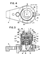
- numeral 1 designates a position detecting apparatus mounted on a table T of a machine tool by a fastening member 4.
- Numeral 6 designates a work to be machined.
- Numeral 11 designates a base including a small-diameter portion 12 having a slot 13 on its upper part as shown in (c) of Fig. 5 and a central hole 14 made through it and comprising a large-diameter portion and a small-diameter portion.
- Numeral 15 designates a proximity switch centrally positioned within the hole 14 and attached to the base 11 by a member 17.
- Numeral 16 designates a connector for bringing the lead wire of the proximity switch 15 to the outside.
- Numeral 18 designates a bottomed cylindrical proximity member having a pair of elongated holes 19 in its bottom portion as shown by the c-c sectional view in (c) of Fig. 5.
- the elongated holes 19 are engaged with the small-diameter portion 12 of the base 11 and the proximity member 18 is slidable in the X and Y directions over the base 11.
- Numeral 20 designates a rectangular sensing hole formed in the bottom portion of the proximity member 18 and its longitudinal center is displaced by a distance t from the center of a sensing element a of the proximity switch 15.
- Numeral 21 designates a notch formed in one side wall of the sensing hole 20 as shown in (c) of Fig. 5.
- Numeral 22 designates a cylindrical coupling member fastened to the base 11 by screws.
- Numeral 23 designates a cylindrical connecting member through which a rod 24 is fixedly extended as shown in the B-B sectional view in (b) of Fig. 5, and the rod 24 is slidably inserted into the coupling member 22.
- Numeral 25 designates a pair of blind holes formed in the coupling member 23 to extend parallel to the rod 24, and a pair of springs 27 is disposed between the blind holes 25 and a pair of tapped holes 26 formed in the coupling member 22 so that the coupling member 23 is always urged in the direction of the arrow and a gap is formed between the coupling members 22 and 23.
- a rod 28 is fitted in the upper part of the coupling member 23 to cross the rod 24 at right angles, and the rod 28 is slidably inserted into a sliding plate 30 positioned on the proximity member 28.
- Numeral 29 designates a pair of blind holes formed in the coupling member 23 to extend parallel to the rod 28, and a pair of springs 32 is disposed between a pair of tapped holes 31 formed in the sliding plate 30 and the blind holes 29 in such a manner that the coupling member 23 is always urged in the direction of the arrow and a gap g 1 is formed between the coupling member 23 and the sliding plate 30.
- the proximity member 18 and the sliding plate 30 are joined together by screws.
- Numeral 33 designates a contactor positioned on the sliding plate 30 by a locating pin 34 and fixed in position by screws.
- the upper surface of the contactor 33 is cut out at right angles to form a recessed portion 35 which in turn provides an X-axis direction contact surface 36 and a Y-axis direction contact surface 37.
- the position detecting apparatus 1 is first fixedly mounted on the table T by the fastening member 4 as shown in Fig.2. Then, a measuring element 5 comprising a rod of a small temperature coefficient is fitted on the spindle S of the machine tool and the table T is moved while lowering the bed B thus fitting the measuring element 5 in the recessed portion 35 of the contactor 33 in the position detecting apparatus 1. In this condition, if the table T is moved in the x direction (Fig. 4), the measuring element 5 is pressed against the x-axis direction contact surface 36 of the contactor 33 and the contactor 33 is displaced in an x 1 direction.
- the contactor 5 is pressed against the y-axis direction contact surface 37 and the contactor 33 is displaced in a y 1 direction.
- the proximity member 18 is displaced in the y 1 direction and also the connecting member 23 is displaced in the y 1 direction by way of the rod 24 against springs 27.
- the sensing element a of the proximity switch 15 is first brought opposite to the notch 21 of the sensing hole 18 and it is stopped temporarily.
- the proximity member 18 is displaced further in the y 1 direction, as shown in (c) of Fig.
- a wall surface 20y overlaps the sensing element a and the overlapping reaches a predetermined area.
- the proximity switch 15 is operated and its output signal is sent as a y-axis count value to the NC control panel. Simultaneously, the table T is stopped.
- the coordinates of the NC control panel are subjected to zero point calibration and the resulting point is used as the coordinates origin.
- an additional function of stopping the movement of the table upon actuation of the proximity switch must be provided in addition to the position detecting apparatus of this invention.
- a proximity switch actuation indicative signal may be applied to the NC control panel to automatically stop the table.
- the repetitive accuracy of the proximity switch is dependent on the closing rate of the proximity member and the time interval between the time of actuation of the proximity switch and the time of stopping the table and the repetition accuracy can be improved to about ⁇ 1 by making the closing rate of the proximity member sufficiently low.
Landscapes
- Engineering & Computer Science (AREA)
- Physics & Mathematics (AREA)
- General Physics & Mathematics (AREA)
- Human Computer Interaction (AREA)
- Manufacturing & Machinery (AREA)
- Automation & Control Theory (AREA)
- Mechanical Engineering (AREA)
- Aviation & Aerospace Engineering (AREA)
- Machine Tool Sensing Apparatuses (AREA)
- Automatic Control Of Machine Tools (AREA)
- Measurement Of Length, Angles, Or The Like Using Electric Or Magnetic Means (AREA)
Applications Claiming Priority (2)
| Application Number | Priority Date | Filing Date | Title |
|---|---|---|---|
| JP55156987A JPS5918183B2 (ja) | 1980-11-10 | 1980-11-10 | 工作機械主軸の位置検出装置 |
| JP156987/80 | 1980-11-10 |
Publications (2)
| Publication Number | Publication Date |
|---|---|
| EP0051937A1 true EP0051937A1 (fr) | 1982-05-19 |
| EP0051937B1 EP0051937B1 (fr) | 1984-12-19 |
Family
ID=15639691
Family Applications (1)
| Application Number | Title | Priority Date | Filing Date |
|---|---|---|---|
| EP81304921A Expired EP0051937B1 (fr) | 1980-11-10 | 1981-10-20 | Dispositif pour détecter la position de la broche d'une machine-outil |
Country Status (5)
| Country | Link |
|---|---|
| US (1) | US4413422A (fr) |
| EP (1) | EP0051937B1 (fr) |
| JP (1) | JPS5918183B2 (fr) |
| KR (1) | KR880001720B1 (fr) |
| DE (2) | DE51937T1 (fr) |
Cited By (2)
| Publication number | Priority date | Publication date | Assignee | Title |
|---|---|---|---|---|
| US4590580A (en) * | 1982-10-12 | 1986-05-20 | Kabushiki Kaisha Okuma Tekkosho | Automatic measurement/compensation apparatus for tool diameter |
| CN106706158A (zh) * | 2016-11-09 | 2017-05-24 | 北京工业大学 | 一种监测机床基础温度变化的实验装置 |
Families Citing this family (9)
| Publication number | Priority date | Publication date | Assignee | Title |
|---|---|---|---|---|
| US4750272A (en) * | 1986-11-06 | 1988-06-14 | Kearney & Trecker Corporation | Tool measuring device employing gap width detection |
| US4784539A (en) * | 1987-05-18 | 1988-11-15 | Manuflex Corporation | Tool communications method |
| US5908994A (en) * | 1997-11-20 | 1999-06-01 | Malczewski; Edmund A. | Tram monitor |
| DE19756498A1 (de) * | 1997-12-19 | 1999-06-24 | Weinig Michael Ag | Maschine zum Bearbeiten von Werkstücken aus Holz, Kunststoff und dergleichen, vorzugsweise Kehlmaschine, sowie Verfahren zur Verstellung der Spindel einer solchen Maschine |
| JP3405965B2 (ja) * | 2000-07-06 | 2003-05-12 | ファナック株式会社 | 工作機械の熱変位補正方法 |
| RU2407988C2 (ru) * | 2009-01-20 | 2010-12-27 | Федеральное государственное автономное образовательное учреждение высшего профессионального образования "ЮЖНЫЙ ФЕДЕРАЛЬНЫЙ УНИВЕРСИТЕТ" | Оптическое устройство для измерения перемещений |
| JP4917665B1 (ja) * | 2010-11-11 | 2012-04-18 | ファナック株式会社 | 工作機械の熱変位補正方法及び熱変位補正装置 |
| CN104501679A (zh) * | 2014-11-26 | 2015-04-08 | 芜湖福马汽车零部件有限公司 | 一种车用空调铸件检具 |
| CN111381560B (zh) * | 2020-04-30 | 2023-01-06 | 中国航发哈尔滨东安发动机有限公司 | 机械加工零点补偿方法和装置 |
Citations (2)
| Publication number | Priority date | Publication date | Assignee | Title |
|---|---|---|---|---|
| US3636814A (en) * | 1969-11-26 | 1972-01-25 | Bendix Corp | Apparatus for and method of checking a tool of a numerically controlled machine |
| US3684939A (en) * | 1971-02-04 | 1972-08-15 | Allied Ind Components | Automatic positioning accessory for numerical control machine tools |
Family Cites Families (7)
| Publication number | Priority date | Publication date | Assignee | Title |
|---|---|---|---|---|
| US3614909A (en) * | 1968-03-15 | 1971-10-26 | Waldrich Werkzeugmasch | Apparatus for adjusting cutting tools for their use in tool machines in particular milling machines |
| JPS5217276A (en) * | 1975-07-31 | 1977-02-09 | Futaba Corp | Reference surface setting device for processing machine |
| US3995528A (en) * | 1975-08-25 | 1976-12-07 | Rohr Industries, Inc. | Tool length compensator for numerically controlled machine |
| DE2540494A1 (de) * | 1975-09-11 | 1977-03-24 | Bosch Gmbh Robert | Vorrichtung zum zentrischen heranfuehren und montieren von maschinenelementen |
| US4118871A (en) * | 1978-06-13 | 1978-10-10 | Kearney & Trecker Corporation | Binary inspection probe for numerically controlled machine tools |
| GB2045437B (en) * | 1979-03-30 | 1984-02-08 | Renishaw Electrical Ltd | Coordinate measuring machine |
| JPS5647704A (en) * | 1979-09-28 | 1981-04-30 | Hitachi Ltd | In-process measuring device |
-
1980
- 1980-11-10 JP JP55156987A patent/JPS5918183B2/ja not_active Expired
-
1981
- 1981-10-20 DE DE198181304921T patent/DE51937T1/de active Pending
- 1981-10-20 DE DE8181304921T patent/DE3167868D1/de not_active Expired
- 1981-10-20 EP EP81304921A patent/EP0051937B1/fr not_active Expired
- 1981-10-23 KR KR1019810004031A patent/KR880001720B1/ko not_active Expired
- 1981-11-05 US US06/318,364 patent/US4413422A/en not_active Expired - Fee Related
Patent Citations (2)
| Publication number | Priority date | Publication date | Assignee | Title |
|---|---|---|---|---|
| US3636814A (en) * | 1969-11-26 | 1972-01-25 | Bendix Corp | Apparatus for and method of checking a tool of a numerically controlled machine |
| US3684939A (en) * | 1971-02-04 | 1972-08-15 | Allied Ind Components | Automatic positioning accessory for numerical control machine tools |
Cited By (2)
| Publication number | Priority date | Publication date | Assignee | Title |
|---|---|---|---|---|
| US4590580A (en) * | 1982-10-12 | 1986-05-20 | Kabushiki Kaisha Okuma Tekkosho | Automatic measurement/compensation apparatus for tool diameter |
| CN106706158A (zh) * | 2016-11-09 | 2017-05-24 | 北京工业大学 | 一种监测机床基础温度变化的实验装置 |
Also Published As
| Publication number | Publication date |
|---|---|
| KR880001720B1 (ko) | 1988-09-08 |
| KR830008217A (ko) | 1983-11-16 |
| JPS5783342A (en) | 1982-05-25 |
| DE51937T1 (de) | 1984-10-25 |
| US4413422A (en) | 1983-11-08 |
| DE3167868D1 (en) | 1985-01-31 |
| EP0051937B1 (fr) | 1984-12-19 |
| JPS5918183B2 (ja) | 1984-04-25 |
Similar Documents
| Publication | Publication Date | Title |
|---|---|---|
| JP4229698B2 (ja) | 工具の刃先位置の測定方法及び装置、ワークの加工方法、並びに工作機械 | |
| US8244396B2 (en) | Turning machine and machining method by the same | |
| US5387061A (en) | Parameter monitoring compensation system and method | |
| US5357450A (en) | Automated maintenance system for computer numerically controlled machines | |
| US4628441A (en) | Automatic dynamic error compensator | |
| US4413422A (en) | Apparatus for detecting the position of a machine tool spindle | |
| US4195250A (en) | Automatic measuring and tool position compensating system for a numerically controlled machine tool | |
| JP5673855B2 (ja) | 工作機械 | |
| EP1203632B1 (fr) | Machine-outil avec système de contrôle de la position de l'outil | |
| JP4799472B2 (ja) | 工具の刃先位置の測定方法及び装置、ワークの加工方法並びに工作機械 | |
| JP5235284B2 (ja) | 測定方法及び工作機械 | |
| US4784539A (en) | Tool communications method | |
| US8152422B2 (en) | Control method for a machine tool with numerical control | |
| EP0068643A2 (fr) | Procédé et dispositif pour la mise en place d'un outil de tour | |
| US6082016A (en) | Cutting edge measuring device for machine tool | |
| US5224048A (en) | Electric discharge machine including electrode configuration sensor | |
| JP6721805B1 (ja) | 工作機械 | |
| US8920080B2 (en) | Machine tool | |
| US20240424629A1 (en) | Machine tool | |
| JP2005088172A (ja) | 工作機械の変位量確認用加工方法及び変位量確認用工作物 | |
| CN222359792U (zh) | 数控机床温度补偿装置 | |
| TWI796094B (zh) | 應用於工具機的熱變位量測系統及方法 | |
| KR940003965B1 (ko) | 다이얼 게이지에 의한 홈 깊이 측정용 지그 | |
| KR102951468B1 (ko) | 지지성질 가변 가능 엔드이펙터 장치 | |
| US20260138227A1 (en) | Compensation value calculation method of position measurement sensor and compensation value calculation system of position measurement sensor in machine tool |
Legal Events
| Date | Code | Title | Description |
|---|---|---|---|
| PUAI | Public reference made under article 153(3) epc to a published international application that has entered the european phase |
Free format text: ORIGINAL CODE: 0009012 |
|
| AK | Designated contracting states |
Designated state(s): BE DE FR GB IT NL SE |
|
| 17P | Request for examination filed |
Effective date: 19820608 |
|
| ITF | It: translation for a ep patent filed | ||
| GRAA | (expected) grant |
Free format text: ORIGINAL CODE: 0009210 |
|
| DET | De: translation of patent claims | ||
| AK | Designated contracting states |
Designated state(s): BE DE FR GB IT NL SE |
|
| REF | Corresponds to: |
Ref document number: 3167868 Country of ref document: DE Date of ref document: 19850131 |
|
| ET | Fr: translation filed | ||
| PLBE | No opposition filed within time limit |
Free format text: ORIGINAL CODE: 0009261 |
|
| STAA | Information on the status of an ep patent application or granted ep patent |
Free format text: STATUS: NO OPPOSITION FILED WITHIN TIME LIMIT |
|
| 26N | No opposition filed | ||
| ITTA | It: last paid annual fee | ||
| PGFP | Annual fee paid to national office [announced via postgrant information from national office to epo] |
Ref country code: GB Payment date: 19920917 Year of fee payment: 12 |
|
| PGFP | Annual fee paid to national office [announced via postgrant information from national office to epo] |
Ref country code: FR Payment date: 19920924 Year of fee payment: 12 |
|
| PGFP | Annual fee paid to national office [announced via postgrant information from national office to epo] |
Ref country code: BE Payment date: 19920928 Year of fee payment: 12 |
|
| PGFP | Annual fee paid to national office [announced via postgrant information from national office to epo] |
Ref country code: SE Payment date: 19921007 Year of fee payment: 12 |
|
| PGFP | Annual fee paid to national office [announced via postgrant information from national office to epo] |
Ref country code: NL Payment date: 19921031 Year of fee payment: 12 |
|
| PGFP | Annual fee paid to national office [announced via postgrant information from national office to epo] |
Ref country code: DE Payment date: 19921214 Year of fee payment: 12 |
|
| PG25 | Lapsed in a contracting state [announced via postgrant information from national office to epo] |
Ref country code: GB Effective date: 19931020 |
|
| PG25 | Lapsed in a contracting state [announced via postgrant information from national office to epo] |
Ref country code: SE Effective date: 19931021 |
|
| PG25 | Lapsed in a contracting state [announced via postgrant information from national office to epo] |
Ref country code: BE Effective date: 19931031 |
|
| BERE | Be: lapsed |
Owner name: KITAMURA KIKAI K.K. (KITAMURA MACHINERY CO. LTD) Effective date: 19931031 |
|
| PG25 | Lapsed in a contracting state [announced via postgrant information from national office to epo] |
Ref country code: NL Effective date: 19940501 |
|
| GBPC | Gb: european patent ceased through non-payment of renewal fee |
Effective date: 19931020 |
|
| NLV4 | Nl: lapsed or anulled due to non-payment of the annual fee | ||
| PG25 | Lapsed in a contracting state [announced via postgrant information from national office to epo] |
Ref country code: FR Effective date: 19940630 |
|
| PG25 | Lapsed in a contracting state [announced via postgrant information from national office to epo] |
Ref country code: DE Effective date: 19940701 |
|
| REG | Reference to a national code |
Ref country code: FR Ref legal event code: ST |
|
| EUG | Se: european patent has lapsed |
Ref document number: 81304921.0 Effective date: 19940510 |