EP0051971A1 - Accouplement, embrayage et/ou frein - Google Patents
Accouplement, embrayage et/ou frein Download PDFInfo
- Publication number
- EP0051971A1 EP0051971A1 EP81305219A EP81305219A EP0051971A1 EP 0051971 A1 EP0051971 A1 EP 0051971A1 EP 81305219 A EP81305219 A EP 81305219A EP 81305219 A EP81305219 A EP 81305219A EP 0051971 A1 EP0051971 A1 EP 0051971A1
- Authority
- EP
- European Patent Office
- Prior art keywords
- clutch
- ring
- discs
- belt
- brake
- Prior art date
- Legal status (The legal status is an assumption and is not a legal conclusion. Google has not performed a legal analysis and makes no representation as to the accuracy of the status listed.)
- Withdrawn
Links
Images

Classifications
-
- F—MECHANICAL ENGINEERING; LIGHTING; HEATING; WEAPONS; BLASTING
- F16—ENGINEERING ELEMENTS AND UNITS; GENERAL MEASURES FOR PRODUCING AND MAINTAINING EFFECTIVE FUNCTIONING OF MACHINES OR INSTALLATIONS; THERMAL INSULATION IN GENERAL
- F16D—COUPLINGS FOR TRANSMITTING ROTATION; CLUTCHES; BRAKES
- F16D55/00—Brakes with substantially-radial braking surfaces pressed together in axial direction, e.g. disc brakes
- F16D55/24—Brakes with substantially-radial braking surfaces pressed together in axial direction, e.g. disc brakes with a plurality of axially-movable discs, lamellae, or pads, pressed from one side towards an axially-located member
- F16D55/26—Brakes with substantially-radial braking surfaces pressed together in axial direction, e.g. disc brakes with a plurality of axially-movable discs, lamellae, or pads, pressed from one side towards an axially-located member without self-tightening action
- F16D55/28—Brakes with only one rotating disc
-
- F—MECHANICAL ENGINEERING; LIGHTING; HEATING; WEAPONS; BLASTING
- F16—ENGINEERING ELEMENTS AND UNITS; GENERAL MEASURES FOR PRODUCING AND MAINTAINING EFFECTIVE FUNCTIONING OF MACHINES OR INSTALLATIONS; THERMAL INSULATION IN GENERAL
- F16D—COUPLINGS FOR TRANSMITTING ROTATION; CLUTCHES; BRAKES
- F16D13/00—Friction clutches
- F16D13/22—Friction clutches with axially-movable clutching members
- F16D13/24—Friction clutches with axially-movable clutching members with conical friction surfaces cone clutches
- F16D13/26—Friction clutches with axially-movable clutching members with conical friction surfaces cone clutches in which the or each axially-movable member is pressed exclusively against an axially-located member
-
- F—MECHANICAL ENGINEERING; LIGHTING; HEATING; WEAPONS; BLASTING
- F16—ENGINEERING ELEMENTS AND UNITS; GENERAL MEASURES FOR PRODUCING AND MAINTAINING EFFECTIVE FUNCTIONING OF MACHINES OR INSTALLATIONS; THERMAL INSULATION IN GENERAL
- F16D—COUPLINGS FOR TRANSMITTING ROTATION; CLUTCHES; BRAKES
- F16D67/00—Combinations of couplings and brakes; Combinations of clutches and brakes
- F16D67/02—Clutch-brake combinations
-
- F—MECHANICAL ENGINEERING; LIGHTING; HEATING; WEAPONS; BLASTING
- F16—ENGINEERING ELEMENTS AND UNITS; GENERAL MEASURES FOR PRODUCING AND MAINTAINING EFFECTIVE FUNCTIONING OF MACHINES OR INSTALLATIONS; THERMAL INSULATION IN GENERAL
- F16D—COUPLINGS FOR TRANSMITTING ROTATION; CLUTCHES; BRAKES
- F16D7/00—Slip couplings, e.g. slipping on overload, for absorbing shock
- F16D7/02—Slip couplings, e.g. slipping on overload, for absorbing shock of the friction type
-
- F—MECHANICAL ENGINEERING; LIGHTING; HEATING; WEAPONS; BLASTING
- F16—ENGINEERING ELEMENTS AND UNITS; GENERAL MEASURES FOR PRODUCING AND MAINTAINING EFFECTIVE FUNCTIONING OF MACHINES OR INSTALLATIONS; THERMAL INSULATION IN GENERAL
- F16D—COUPLINGS FOR TRANSMITTING ROTATION; CLUTCHES; BRAKES
- F16D65/00—Parts or details
- F16D65/02—Braking members; Mounting thereof
- F16D2065/024—Braking members; Mounting thereof the braking surface being inclined with respect to the rotor's axis of rotation at an angle other than 90 degrees, e.g. comprising a conical rotor
Definitions
- the invention relates to a coupling comprising two coaxial discs, to a clutch comprising said coupling, to a slipping clutch or a torque limiting device comprising the coupling, and to a brake comprising said clutch, and also to a clutch and brake assembly.
- the aim of the invention is to provide a device which can be made cheaply, need not be very accurate and operation of which is relatively gentle, avoiding transmission of high shock loads, i.e. a device which can perform as well as the more sophisticated devices without the expensive production techniques being required.
- the invention provides a coupling comprising two coaxial discs, a resilient ring of frictional material positioned between the discs, means retaining the ring substantially coaxially with the discs, and means for biasing the discs into frictional contact with the ring.
- the resilient ring is preferably a torque-transmission belt of the type known as V-belt.
- the invention also relates to a clutch comprising such coupling including means for engagement and disengagement of the discs.
- the invention also relates to a slip clutch comprising a clutch according to the invention and including setting means for the adjustment of the biasing force exerted by the biasing means.
- the invention also relates to a brake comprising a clutch according to the invention in which one of said discs is stationary.
- the invention relates to a clutch and brake assembly
- a clutch and brake assembly comprising a clutch member, a stationary brake member, a dual function clutch/brake member, a first resilient ring between the dual function member and the clutch member, a second resilient ring between the dual function member and the brake member, and a control mechanism for displacing the dual function member between a torque transmitting position in which it presses the first ring onto the clutch member and a braking position in which it presses the second ring onto the brake member.
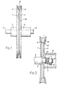
- the clutch as shown in Figure 1 comprises a first disc 1 and a second disc 11 arranged adjacent to and coaxially with each other.
- the discs 1 and 11 are provided on their inner sides, i.e. their mutually adjacent sides, with respective oppositely inclined annular frusto-conical surfaces 2 and 12, hereinafter called flanks 2 and 12, respectively.
- the discs 1 and 11 are provided with respective hubs 3 and 13 by means of which they are connected to respective shafts A and B.
- the shaft A is a driving shaft driven by a motor or internal combustion engine (not shown) and the shaft B is a driven shaft which may drive a working tool or implement (not shown), e.g. a pronged wheel of a tiller.
- the discs 1 and 11 are nearly mirror images of each other.
- the disc 11 is on its inside provided, in addition, with a coaxial cylindrical projection 14 the peripheral surface of which meets the inner periphery of the flank 12, so that the flank 12 and said peripheral surface have substantially the shape of approximately one half of a V-groove of the type used in pulleys.
- a ring 8 in the form of a V-belt of the type used in V-belt drives is positioned between the discs 1, and 11.
- the radially inner periphery of the ring 8 will be called “the base”, the radially outer periphery will be called “the top” and the faces connecting the base and the top will be called “the sides”.
- the clutch is so designed that the ring 8 is with its base slid on the peripheral surface of the projection 14 and is held thereon by friction, while one of the sides of the ring 8 is in contact with the flank 12.
- the clutch includes means (not shown) for engagement and disengagement of the discs 1 and 11, which, when the clutch is engaged, push the discs 1 and 11 towards each other so that their flanks 2 and 12 are pressed on to the sides of the ring 8 whereby frictional contact is established between the discs 1 and 11 via the ring 8, so that, in operation, torque may be transmitted from the disc 1 on to the disc 11, and, when the clutch is disengaged, hold the discs 1 and 11 apart so that there is a sufficient clearance between the flank 2 and the adjacent side of the ring 8.
- the clutch described with reference to the drawing may be modified in a number of ways.
- the discs 1 and 11 need not be nearly identical and substantially planar.
- the disc 1 may be a pressed steel disc the outer rim of which is bent to provide a flank similar to the flank 2.
- At least one of the discs may have at its axial region a recess in its inner side or its axial region may be shaped to extend away from the other disc so that the latter may have his hub on the inner side.
- the discs need not be solid but may be e.g. in the form of an annulus having said flank and attached by radial arms to the hub.
- the ring 8 need not be a V-belt but may be a double V-belt, i.e. a belt which is substantially hexagonal in cross-section.
- a belt 8 of another cross-section e.g. a square or rectangular cross-section could be used but then the flanks of the disc would have to be made so as to be substantially parallel to the sides of the belt.
- the ring need not be situated on the outer periphery of the rings but may be positioned nearer to the axis e.g. in a suitably made groove, and, of course, the clutch may comprise several coaxial rings of different diameter.
- the device shown in Figure 2 is a unit comprising a clutch and a brake shown on the right hand side in the driving position and on the left hand side in the braking position.
- the device comprises a first brake disc 21 carrying a braking ring 22 which are substantially the same as the disc 11 and ring 8 described in connection with Figure 1, except that here the disc 21 is stationary and has a central opening 23 through which passes a driven shaft B.
- the driven shaft carries at its illustrated end a sleeve 24 to which are firmly connected a second brake disc 25 and a first clutch disc 26.
- the sleeve 24 is axially displaceable on the driven shaft B by means of a two-arm lever mechanism 27.
- Figure 2 shows also a driving shaft A which is coaxial with the driven shaft B and carries at its end a second clutch disc 28 carrying a torque transmission ring 29.
- the disc 26 In the driving position the disc 26 is in engagement with the ring 29 while the disc 25 is spaced from the ring 22. In the braking position the disc 26 is spaced from the ring 29 while the disc 25 is in engagement with the ring 22.
- the device shown in Figure 3 shows a second embodiment of a unit comprising a clutch and a brake and is also shown on the right hand side in the driving position and on the left hand side in the braking position.
- the device comprises a stationary brake annulus 31 carrying a braking ring 32.
- a driving shaft A carries at its illustrated end a sleeve 34 to which is firmly connected a clutch disc 36.
- the sleeve 34 is axially displaceable on the driving shaft A by means of a two-arm lever mechanism 37.
- Figure 3 shows also a driven shaft B which is coaxial with the driving shaft A and carries at its end an intermediate disc 38 which carries a torque transmission ring 39.
- the disc 38 is biased by a spring 33.
- the disc 36 In the driving position the disc 36 is pressed against the ring 39 which compresses the spring and disengages the disc 38 from engagement with the ring 32. In the braking position the disc 36 is spaced from the ring 39 while the disc 38 is pressed by the spring 33 into engagement with the ring 32.
- the device shown in Figure 4 is a third embodiment of a unit comprising a clutch and a brake shown on the right hand side in the driving position and on the left hand side in the braking position.
- the device comprises a fixed braking disc 41 carrying a braking ring 42.
- a driving shaft A carries at its illustrated end a clutch disc 46 carrying a torque transmitting ring 49.
- a driven shaft B carries at its illustrated end a sleeve 44 to which is firmly connected an intermediate disc 48.
- the sleeve 44 is axially displaceable on the driven shaft B by means of a two-arm lever mechanism 47.
- Figure 5 shows a torque-limiting device in the form of a slipping clutch comprising a first disc 1 and a second disc 11 having respective oppositely inclined flanks 2 and 12, the second disc 11 having a coaxial cylindrical projection 14 for supporting a ring 8 in the form of a V-belt.
- the elements 1, 11, 2, 12, 14 and 8 substantially the same as described in connection with Fig.1.
- the first disc 1 is connected to a first shaft A (in the illustrated embodiment a driven shaft) and a second disc 11 is connected to a second shaft B (in the illustrated embodiment a driven shaft).
- the shaft A is rod-shaped and has a front part of reduced diameter which has a threaded outer portion 4 and a smooth inner portion 5.
- the shaft B is hollow and the second disc 11 has a sleeve 15 through which passes the front part of the shaft A such that the sleeve 15 is on the smooth portion 5 and the threaded portion 4 protudes into the shaft B and carries a nut 6.
- a compression spring 7 is situated between the nut 6 and the sleeve 15.
- the force exerted by the spring 7 onto the sleeve 15, and thereby the force pressing the flank 2 onto the ring 8, which determines the torque at which the clutch begins to slip, is controlled by the nut 6.
- the nut 6 may be a locking nut or an additional lock nut may be provided.
- devices as shown in Fig.5 could be used in association with ground wheels of a power driven appliance, such as a mower, to act in a manner akin to a differential, by limiting the torque transmitted to the inner wheel when the appliance is being turned into a different direction of travel.
Landscapes
- Engineering & Computer Science (AREA)
- General Engineering & Computer Science (AREA)
- Mechanical Engineering (AREA)
- Mechanical Operated Clutches (AREA)
Applications Claiming Priority (4)
| Application Number | Priority Date | Filing Date | Title |
|---|---|---|---|
| GB8036152 | 1980-11-11 | ||
| GB8036152 | 1980-11-11 | ||
| GB8104785 | 1981-02-16 | ||
| GB8104785 | 1981-02-16 |
Publications (1)
| Publication Number | Publication Date |
|---|---|
| EP0051971A1 true EP0051971A1 (fr) | 1982-05-19 |
Family
ID=26277475
Family Applications (1)
| Application Number | Title | Priority Date | Filing Date |
|---|---|---|---|
| EP81305219A Withdrawn EP0051971A1 (fr) | 1980-11-11 | 1981-11-03 | Accouplement, embrayage et/ou frein |
Country Status (1)
| Country | Link |
|---|---|
| EP (1) | EP0051971A1 (fr) |
Cited By (4)
| Publication number | Priority date | Publication date | Assignee | Title |
|---|---|---|---|---|
| GB2165320A (en) * | 1984-10-05 | 1986-04-09 | Eric Anthony Murray | Clutch |
| GB2182106A (en) * | 1985-09-19 | 1987-05-07 | Alps Electric Co Ltd | A torque takeout mechanism for rotary parts |
| FR2706957A1 (fr) * | 1993-06-24 | 1994-12-30 | Concone Edmond | |
| FR2917796A1 (fr) * | 2007-06-20 | 2008-12-26 | France Reducteurs Soc Par Acti | Dispositif de freinage d'un corps allonge rotatif, tel qu'un arbre rotatif, et transmission integrant un tel dispositif de freinage |
Citations (12)
| Publication number | Priority date | Publication date | Assignee | Title |
|---|---|---|---|---|
| GB170692A (en) * | 1920-08-06 | 1921-11-03 | Frederic Hungerford Bowman | Improvements relating to the transmission of power in and to the electrical equipment of motor vehicles, aircraft, and the like |
| US1948910A (en) * | 1930-07-21 | 1934-02-27 | Reo Motor Car Co | Thermostatic shutter control |
| US2465810A (en) * | 1947-07-12 | 1949-03-29 | Donald O Macdonald | Fluid operated clutch mechanism |
| FR1084122A (fr) * | 1953-09-30 | 1955-01-17 | Dispositif d'embrayage | |
| GB752908A (en) * | 1954-02-26 | 1956-07-18 | Gen Control Company | Improvements in or relating to mechanical clutches |
| US2824435A (en) * | 1955-07-29 | 1958-02-25 | Hochreuter Johann | Elastic shaft couplings |
| US2985992A (en) * | 1958-12-15 | 1961-05-30 | Vestel O Dowdle | Clutch and brake mechanism for a rotary-type mowing machine |
| US3042166A (en) * | 1958-09-22 | 1962-07-03 | Bliss E W Co | Fluid torque limiter |
| US3199312A (en) * | 1963-02-25 | 1965-08-10 | Clarence O Glasgow | Torque coupling and safety clutch device |
| DE1425313A1 (de) * | 1962-06-25 | 1968-10-17 | Lohmann & Stolterfoht Ag | Doppelkegelreibungskupplung |
| US4114732A (en) * | 1976-12-10 | 1978-09-19 | Dunn Robert C | Disc Brake |
| US4187732A (en) * | 1976-11-12 | 1980-02-12 | Kawasaki Jukogyo Kabushiki Kaisha | Sheave assembly for V-belt type infinitely variable transmissions |
-
1981
- 1981-11-03 EP EP81305219A patent/EP0051971A1/fr not_active Withdrawn
Patent Citations (12)
| Publication number | Priority date | Publication date | Assignee | Title |
|---|---|---|---|---|
| GB170692A (en) * | 1920-08-06 | 1921-11-03 | Frederic Hungerford Bowman | Improvements relating to the transmission of power in and to the electrical equipment of motor vehicles, aircraft, and the like |
| US1948910A (en) * | 1930-07-21 | 1934-02-27 | Reo Motor Car Co | Thermostatic shutter control |
| US2465810A (en) * | 1947-07-12 | 1949-03-29 | Donald O Macdonald | Fluid operated clutch mechanism |
| FR1084122A (fr) * | 1953-09-30 | 1955-01-17 | Dispositif d'embrayage | |
| GB752908A (en) * | 1954-02-26 | 1956-07-18 | Gen Control Company | Improvements in or relating to mechanical clutches |
| US2824435A (en) * | 1955-07-29 | 1958-02-25 | Hochreuter Johann | Elastic shaft couplings |
| US3042166A (en) * | 1958-09-22 | 1962-07-03 | Bliss E W Co | Fluid torque limiter |
| US2985992A (en) * | 1958-12-15 | 1961-05-30 | Vestel O Dowdle | Clutch and brake mechanism for a rotary-type mowing machine |
| DE1425313A1 (de) * | 1962-06-25 | 1968-10-17 | Lohmann & Stolterfoht Ag | Doppelkegelreibungskupplung |
| US3199312A (en) * | 1963-02-25 | 1965-08-10 | Clarence O Glasgow | Torque coupling and safety clutch device |
| US4187732A (en) * | 1976-11-12 | 1980-02-12 | Kawasaki Jukogyo Kabushiki Kaisha | Sheave assembly for V-belt type infinitely variable transmissions |
| US4114732A (en) * | 1976-12-10 | 1978-09-19 | Dunn Robert C | Disc Brake |
Cited By (7)
| Publication number | Priority date | Publication date | Assignee | Title |
|---|---|---|---|---|
| GB2165320A (en) * | 1984-10-05 | 1986-04-09 | Eric Anthony Murray | Clutch |
| GB2182106A (en) * | 1985-09-19 | 1987-05-07 | Alps Electric Co Ltd | A torque takeout mechanism for rotary parts |
| GB2182106B (en) * | 1985-09-19 | 1989-11-15 | Alps Electric Co Ltd | An assembly incorporating an electronic part |
| FR2706957A1 (fr) * | 1993-06-24 | 1994-12-30 | Concone Edmond | |
| WO1995000768A1 (fr) * | 1993-06-24 | 1995-01-05 | Concone, Edmond | Dispositif de freinage et d'accouplement a surfaces de friction tronconiques |
| FR2917796A1 (fr) * | 2007-06-20 | 2008-12-26 | France Reducteurs Soc Par Acti | Dispositif de freinage d'un corps allonge rotatif, tel qu'un arbre rotatif, et transmission integrant un tel dispositif de freinage |
| US8210324B2 (en) | 2007-06-20 | 2012-07-03 | France Reducteurs | Device for braking an elongated rotating body, such as a rotary shaft, and transmission integrating such a braking device |
Similar Documents
| Publication | Publication Date | Title |
|---|---|---|
| US4400996A (en) | Positive clutch differential | |
| US4526063A (en) | Three mode differential | |
| US4566570A (en) | Overload clutch | |
| US5301779A (en) | Friction clutch | |
| US4057131A (en) | Multiple disk clutch stamped adapter ring | |
| GB2112478A (en) | Friction overload clutch | |
| EP0355083B1 (fr) | Dispositif pour réduction de vibrations mécaniques dans un embrayage de véhicule | |
| SU826974A3 (ru) | Фрикционна муфта | |
| GB2055996A (en) | Slipping clutch | |
| US4721194A (en) | Clutch rocker mechanism for transfer case | |
| US2464675A (en) | Speed responsive clutch | |
| GB2109499A (en) | Braking device incorporating a slipping clutch | |
| US4924988A (en) | Clutch | |
| US5743367A (en) | Multiple plate friction clutch with axial stop | |
| EP0051971A1 (fr) | Accouplement, embrayage et/ou frein | |
| US5531307A (en) | Shear element type clutch | |
| US3453905A (en) | Differential brake for differential gears of motor vehicles | |
| GB2278898A (en) | Rotation transmission device | |
| US4561855A (en) | Friction clutch | |
| US2561913A (en) | Overload release coupling | |
| US4940126A (en) | Diaphragm spring clutch | |
| US4852709A (en) | Synchronizing apparatus for a power transmission | |
| GB2209194A (en) | A multiple friction disc clutch and flywheel assembly | |
| CA1171694A (fr) | Differentiel avec embrayage a organes de prise dentes | |
| SU497429A1 (ru) | Фрикционна предохранительна муфта |
Legal Events
| Date | Code | Title | Description |
|---|---|---|---|
| PUAI | Public reference made under article 153(3) epc to a published international application that has entered the european phase |
Free format text: ORIGINAL CODE: 0009012 |
|
| AK | Designated contracting states |
Designated state(s): AT BE CH DE FR GB IT LU NL SE |
|
| 16A | New documents despatched to applicant after publication of the search report |
Free format text: 8291 |
|
| 17P | Request for examination filed |
Effective date: 19821102 |
|
| STAA | Information on the status of an ep patent application or granted ep patent |
Free format text: STATUS: THE APPLICATION IS DEEMED TO BE WITHDRAWN |
|
| 18D | Application deemed to be withdrawn |
Effective date: 19850531 |
|
| RIN1 | Information on inventor provided before grant (corrected) |
Inventor name: BEATTIE, CHARLES EDWARD Inventor name: HAZLEWOOD, ANTHONY SELWYN |