EP0052024A1 - Optoelektronische Anordnung für die videofrequente Bildanalyse durch Abtastung - Google Patents
Optoelektronische Anordnung für die videofrequente Bildanalyse durch Abtastung Download PDFInfo
- Publication number
- EP0052024A1 EP0052024A1 EP81401545A EP81401545A EP0052024A1 EP 0052024 A1 EP0052024 A1 EP 0052024A1 EP 81401545 A EP81401545 A EP 81401545A EP 81401545 A EP81401545 A EP 81401545A EP 0052024 A1 EP0052024 A1 EP 0052024A1
- Authority
- EP
- European Patent Office
- Prior art keywords
- video
- detectors
- signals
- circuit
- frequency
- Prior art date
- Legal status (The legal status is an assumption and is not a legal conclusion. Google has not performed a legal analysis and makes no representation as to the accuracy of the status listed.)
- Granted
Links
- 238000010191 image analysis Methods 0.000 title description 2
- 230000003321 amplification Effects 0.000 claims abstract description 25
- 238000003199 nucleic acid amplification method Methods 0.000 claims abstract description 25
- 238000012937 correction Methods 0.000 claims abstract description 20
- 238000005259 measurement Methods 0.000 claims abstract description 12
- 238000012545 processing Methods 0.000 claims abstract description 11
- 230000004907 flux Effects 0.000 claims abstract description 8
- 238000001514 detection method Methods 0.000 claims abstract description 7
- 230000005693 optoelectronics Effects 0.000 claims description 7
- 239000003990 capacitor Substances 0.000 claims description 3
- 210000001747 pupil Anatomy 0.000 claims description 3
- 230000003287 optical effect Effects 0.000 description 20
- 238000010586 diagram Methods 0.000 description 5
- 235000021183 entrée Nutrition 0.000 description 3
- 210000000887 face Anatomy 0.000 description 3
- 230000006870 function Effects 0.000 description 3
- 238000005070 sampling Methods 0.000 description 3
- 230000009471 action Effects 0.000 description 2
- 238000004458 analytical method Methods 0.000 description 2
- 210000004027 cell Anatomy 0.000 description 2
- 230000006835 compression Effects 0.000 description 2
- 238000007906 compression Methods 0.000 description 2
- 230000008030 elimination Effects 0.000 description 2
- 238000003379 elimination reaction Methods 0.000 description 2
- 238000000034 method Methods 0.000 description 2
- 239000010453 quartz Substances 0.000 description 2
- VYPSYNLAJGMNEJ-UHFFFAOYSA-N silicon dioxide Inorganic materials O=[Si]=O VYPSYNLAJGMNEJ-UHFFFAOYSA-N 0.000 description 2
- 230000001360 synchronised effect Effects 0.000 description 2
- 238000012360 testing method Methods 0.000 description 2
- 238000012935 Averaging Methods 0.000 description 1
- 230000008878 coupling Effects 0.000 description 1
- 238000010168 coupling process Methods 0.000 description 1
- 238000005859 coupling reaction Methods 0.000 description 1
- 230000006866 deterioration Effects 0.000 description 1
- 230000002542 deteriorative effect Effects 0.000 description 1
- 230000006386 memory function Effects 0.000 description 1
- 230000001483 mobilizing effect Effects 0.000 description 1
- 230000000737 periodic effect Effects 0.000 description 1
- 230000004044 response Effects 0.000 description 1
- 238000006467 substitution reaction Methods 0.000 description 1
Images


Classifications
-
- G—PHYSICS
- G02—OPTICS
- G02B—OPTICAL ELEMENTS, SYSTEMS OR APPARATUS
- G02B26/00—Optical devices or arrangements for the control of light using movable or deformable optical elements
- G02B26/08—Optical devices or arrangements for the control of light using movable or deformable optical elements for controlling the direction of light
- G02B26/0875—Optical devices or arrangements for the control of light using movable or deformable optical elements for controlling the direction of light by means of one or more refracting elements
- G02B26/0883—Optical devices or arrangements for the control of light using movable or deformable optical elements for controlling the direction of light by means of one or more refracting elements the refracting element being a prism
- G02B26/0891—Optical devices or arrangements for the control of light using movable or deformable optical elements for controlling the direction of light by means of one or more refracting elements the refracting element being a prism forming an optical wedge
-
- H—ELECTRICITY
- H04—ELECTRIC COMMUNICATION TECHNIQUE
- H04N—PICTORIAL COMMUNICATION, e.g. TELEVISION
- H04N3/00—Scanning details of television systems; Combination thereof with generation of supply voltages
- H04N3/02—Scanning details of television systems; Combination thereof with generation of supply voltages by optical-mechanical means only
- H04N3/06—Scanning details of television systems; Combination thereof with generation of supply voltages by optical-mechanical means only having a moving lens or other refractor
Definitions
- the present invention relates to an opto-electronic device for analyzing a video-frequency image by scanning, comprising a device for correcting thermal drifts.
- the detectors are presented, at the end of each image scan, with a device, for example a test pattern, making it possible to produce a uniform light flux on all the detectors, and the signals of each detector can be corrected, for each scan of image, by a correction loop by subtracting for each detector, the memorized value corresponding to the detected uniform flux.
- This correction device associating a correction loop and a test pattern uses pre-amplifiers provided with an input capacity to retain the continuous components of the signals since the registration takes place at each image.
- the periodic registration allows to reset each measurement chain before each image scan, which allows to take into account the elimination of the continuous components of the signals and to compensate for the thermal drifts in particular of the first stage of amplification of the signals of each detector, without however deteriorate the image restitution.
- the time constants of the inputs of the pre-amplifiers are chosen for this purpose so that continuous signals are not weakened by more than 1% during a image scanning period.
- the use of such a correction device has the drawback of mobilizing a large part of the processing time (at least 25%) solely for registration operations which must imperatively be performed for each image.
- the use of such a correction device in an opto-electronic device for image analysis by rotary scanning would furthermore require that part of the image be lost, especially in the central area.
- the subject of the present invention is a device for analyzing video-frequency images by scanning, comprising a correction device which does not have the abovementioned faults and in particular the readjustment of which, carried out during an initialization phase, remains valid for a fairly long duration (typically a few minutes).
- FIG. 1a represents an opto-electronic device for analyzing video-frequency images by scanning comprising a scanning optic 22 driven by mechanical means 23 for example in rotation, so as to produce an image scanning, a scanning optic focusing 24 on a detection device D comprising at least one network of detectors.
- Video-frequency means for processing the detection signals include in particular AC amplification circuits of the detector signals, each amplification circuit being connected to the corresponding detector by a continuous link, that is to say non-capacitive, thus than a correction device.
- the correction device comprises a so-called occultation device 20 (or 27), FIG. 1b with two states, the first corresponding to the reception by the detectors of the network of a uniform flow, and the second to the reception by them of the video-frequency image (state normal operation of the analysis device).
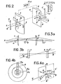
- FIG. 2 represents two cylindrical optical elements 1 and 2, namely two cylindrical lenses comprising generators 3 and 4 respectively.
- the two cylindrical optical elements 1 and 2 are driven integrally in rotation by means of a DMR device. This rotation occurs around an axis XX 'perpendicular to the direction of the generatrices 3 and 4.
- a focusing optic F arranged downstream focuses the rays exiting from the cylindrical element 2 on a network of detectors D disposed in its focal plane and comprising a plurality of detectors extending from the optical axis XX 'of the device.
- the light rays corresponding to the image analyzed are introduced at the input of the cylindrical optical element 1, possibly by means of optical reception means R consisting for example of a reception dome and / or of a return optic .
- the integral rotation of the cylindrical optical elements 1 and 2 will produce a rotary scanning of the image on the detector array D.
- Video-frequency processing means T of the detector signals are associated with the detectors in the detector network D.
- FIG. 2 two incident light rays have also been shown at a point O on the cylindrical optical element 1. These two light rays make angles ⁇ and p respectively with the axis XX ′.
- the radius which makes an angle ⁇ with the axis XX ' is located in a plane xOy perpendicular to the generatrices 3 of the element 1.
- the radius which makes an angle A with the axis XX' is located in a plane xOz parallel to generators 3.
- Figure 3a is a section in the xOy plane, where the cylindrical optical elements which are in the envisaged case of cylindrical lenses, can be likened to converging lenses.
- the two focal points of the lenses shown in FIG. 2a are combined, so as to produce an afocal system and the radius exiting from the lens 2 will form an angle - ⁇ 'defined with the relation: where f and f 2 are the respective focal distances of the lens 1 and the lens 2.
- FIG. 3b represents a section through a plane passing through O and parallel to the generatrices, namely the plane xOz.
- the lenses 1 and 2 are blades with parallel faces, and consequently any incident ray at an angle ⁇ relative to the axis Ox will also emerge with an angle In FIG. 1, the ray has been shown outgoing correspondent.
- FIG. 4a where the points O, O 'and O "have by convention been shown together, the angular deviations of each of the above-mentioned incident rays have been shown, in the case where the focal distances of the lenses 1 and 2 are equal.
- the deviations return to the product of a symmetry with respect to a point, by a symmetry with respect to a plane, said plane containing the axes X X ′ and z z ′, that is to say a plane parallel to the axis of rotation XX ′ of the cylindrical optical elements and their generatrices, and everything therefore takes place as if a fictitious mirror were located in the plane xOz.
- FIG. 4b represents the circular scanning obtained when the focal distances of the two lenses are equal.
- a network of detectors (D 1 , D 2 ' ... D n ) regularly spaced and extending from the axis XX' whose trace corresponds to a detector D 1 at the end of the network will be scanned by rotation of the image.
- FIGS. 5a and 5b illustrate an embodiment in which the incident light rays are returned to the entry of a group of two cylindrical lenses 7 and 8, by means of a beam folding device of the Cassegrain type which comprises a main mirror 5 provided with an axial opening and a secondary mirror 6.
- a converging lens 9 focuses the light rays exiting from the cylindrical lens 8 on the detector D.
- the axis passing through the center of the spherical mirror 6 and perpendicular to the generating the cylindrical lenses 7 and 8 defines the optical axis of the system.
- FIG. 5a which is a section of the system by a plane parallel to the generatrices of the lenses 7 and 8, there is shown a beam parallel to the optical axis of the system and which is transformed by all of the mirrors 5 and 6 into a beam parallel to the optical axis of the system.
- the cylindrical lenses 7 and 8 are comparable to blades with parallel faces, the parallel beam will be focused on the detectors by the converging lens 9. We will therefore have a virtual image in the center of the spherical lens 6 and a real image of the same direction focused on the detectors.
- FIG. 5b which is a section through a plane perpendicular to the generatrices of the cylindrical lenses 7 and 8, the beam parallel to the optical axis is also returned by the assembly of the mirror 5 and 6 in the form of parallel rays.
- the cylindrical lens 7, which in this plane is comparable to a converging lens will focus these rays in its focal plane, and the cylindrical lens 8 will transform the rays into a beam parallel to the optical axis which will be taken up by the converging lens 9 and focused on the network of detectors D.
- FIGS. 6a and 6b show a variant of FIGS. 5a and 5b in which the spherical mirror 6 and the cylindrical lens 7 are replaced by a cylindrical mirror 10 whose generatrices are perpendicular to the generatrices of the cylindrical lens 8.
- FIG. 6a which is a section through a plane parallel to the generatrices of the cylindrical lens 8
- a beam parallel to the optical axis of the system is returned in a parallel beam by the cylindrical mirror 10, which, in this plane, can be assimilated to a spherical mirror.
- the parallel beam is taken up by the cylindrical lens 8 which, in this plane, is comparable to a blade with parallel faces, and then focused on the array of detectors D by the converging lens 9.
- this plane therefore, there is a virtual image at a point corresponding to the center of the cylindrical mirror 10, and a real image at the level of the detector network and in the same direction as the other.
- FIG. 6b which is a section through a plane perpendicular to the generatrices of the cylindrical lens 8 a beam parallel to the optical axis of the system is returned by the cylindrical lens 10 which, in this plane, is comparable to a plane mirror.
- This beam converges in a plane corresponding to the focal point of the cylindrical lens 8 which, in this plane, is comparable to a converging lens and forms at the exit of the latter a parallel beam which is taken up by the converging lens 9 and focused on the network of detectors D.
- Figures 7a and 7b are variants of Figures 6a and 6b, where the main mirror 5 is replaced by a converging lens 11 provided with an axial opening.
- the optical diagrams represented correspond to those of FIGS. 6a and 6b. Such a substitution is of course also possible in the case of FIGS. 5a and 5b.
- the detectors are also arranged in the form of a network and see the image scroll transversely with respect to the axis of the network, and the reconstruction of the image is similar, with the differences in systems coordinates.
- FIG. 8 represents an electronic assembly for video-frequency processing of the detector signals.
- Each amplifier is associated with an amplification circuit composed of a PA preamplifier and an amplifier A, a continuous background corrector CFC which removes the continuous components from the measurement signals and a low-pass filter PB, intended to limit the bandwidth, therefore to improve the signal / noise ratio.
- the amplified and filtered voltages are introduced into a multiplexing and correction block 37.
- This block comprises a multiplexing and digital coding circuit MN and a residual voltage correction circuit COR.
- a bus line 35 sequentially introduces the values measured into a memory M.
- the signal sampling is synchronized for example from a quartz Q which drives a motor MO driving the optical elements in rotation in a manner known per se.
- the sequencer 45 introduces progressively the values corresponding to the coordinates into the memory M in response to a command provided by the aforementioned synchronization and corresponding to the start of a new multiplexing of the n detectors.
- the measured values will thus be stored in memory, for example line by line and image by image according to a table corresponding to Cartesian coordinates.
- a synchronized TV video processing unit preferably by quartz Q, will sequentially generate television images line by line.
- the subtractor circuit CS sequentially subtracts from each value measured by each detector, the content of the memory M relating to the corresponding detector. Its function, which will be explained below, is to allow an initialization of all the detectors before the devices are put into service, or at defined time intervals.
- An initialization allowing the elimination of the residual voltages corresponding to the notably thermal drift of the inputs of the amplification circuits and in particular of the pre-amplifiers of the detectors is carried out either once and for all during the commissioning of the device, or every N images , N being a function of the tolerated drifts.
- An initialization is carried out by subjecting all the detectors to a uniform flux, for example by occultation of the system. The values measured by each detector under these predetermined conditions are stored in the memory M and then subtracted from the measurement values of the corresponding detectors, which are sampled during an image detection.
- a signal corresponding to a detector D h is introduced into an amplification circuit 47.
- the signals leaving the amplifier 47 are introduced into an averaging circuit 48 which also receives the signals from all the other detectors composing the network of detectors, and produces at its output an average value V.
- This average value is injected into an amplifier 49 possibly integrating whose output signal s h is fed back into feedback at the input of the amplifier 47.
- the system will control the output of the amplifier 47 referenced S h to deliver a signal centered with respect to the average value of all the signals.
- FIG. 11 represents an embodiment of the diagram of FIG. 10.
- a signal produced by a detector D 1 is introduced at the negative input of a preamplifier PA1 which includes a feedback resistance 38.
- the signals in PA1 amplifier outputs are introduced into an amplifier A1 which includes an input resistance 39, a feedback resistance 40, as well as an output SI.
- the signals coming from a detector D 2 are introduced at the negative input of a preamplifier PA2 comprising a feedback resistance 41.
- the signals leaving the preamplifier Cator PA2 are introduced into an amplifier A2 comprising an input resistance 42 and a feedback resistance 43 as well as an output S 2 .
- the outputs S 1 , S 2 , S 3 , S 4 , ... S n which correspond to measurement chains whose gains have been adjusted so as to correspond to globally equal gains, are connected via resistors of equal values respectively R 1 , R 2 , R 3 , R 4 , ... R n at a common point M. Between this point M and the ground is placed a capacitor C 1 .
- the point M is also connected to the negative input of an integrator 49 comprising an input resistance 44 and a feedback capacitor C 2 .
- the output of the integrator 49 is connected, via the resistive links s 1 , s 2 , s 3 , s 4 , ... s n to the negative inputs of the pre-amplifiers corresponding to each of the detectors making up the network of detectors.
- FIG. 12a represents amplified signals supplied by a system with four detectors D 1 , D 2 , D 3 , D 4 . We see that the average value is located at a value V very different from the 0 volt level.
- FIG. 12b represents the signals corresponding to the detectors D 1 , D 2 , D 3 and D 4 when a circuit as described in FIGS. 10 and 11 is used. The values represented are centered around the value 0 volts. The continuous component of the signals has thus been eliminated without deteriorating the relative continuous information of the signals.
Landscapes
- Physics & Mathematics (AREA)
- General Physics & Mathematics (AREA)
- Optics & Photonics (AREA)
- Engineering & Computer Science (AREA)
- Multimedia (AREA)
- Signal Processing (AREA)
- Photometry And Measurement Of Optical Pulse Characteristics (AREA)
- Transforming Light Signals Into Electric Signals (AREA)
- Gyroscopes (AREA)
Applications Claiming Priority (2)
| Application Number | Priority Date | Filing Date | Title |
|---|---|---|---|
| FR8022275A FR2492616A1 (fr) | 1980-10-17 | 1980-10-17 | Dispositif opto-electronique d'analyse d'images video-frequence par balayage rotatif |
| FR8022275 | 1980-10-17 |
Publications (2)
| Publication Number | Publication Date |
|---|---|
| EP0052024A1 true EP0052024A1 (de) | 1982-05-19 |
| EP0052024B1 EP0052024B1 (de) | 1984-09-12 |
Family
ID=9247038
Family Applications (2)
| Application Number | Title | Priority Date | Filing Date |
|---|---|---|---|
| EP81401545A Expired EP0052024B1 (de) | 1980-10-17 | 1981-10-06 | Optoelektronische Anordnung für die videofrequente Bildanalyse durch Abtastung |
| EP81401544A Expired EP0050546B1 (de) | 1980-10-17 | 1981-10-06 | Optoelektronische Anordnung für die videofrequente Bildanalyse durch rotierende Abtastung |
Family Applications After (1)
| Application Number | Title | Priority Date | Filing Date |
|---|---|---|---|
| EP81401544A Expired EP0050546B1 (de) | 1980-10-17 | 1981-10-06 | Optoelektronische Anordnung für die videofrequente Bildanalyse durch rotierende Abtastung |
Country Status (4)
| Country | Link |
|---|---|
| US (2) | US4393408A (de) |
| EP (2) | EP0052024B1 (de) |
| DE (2) | DE3163099D1 (de) |
| FR (1) | FR2492616A1 (de) |
Cited By (8)
| Publication number | Priority date | Publication date | Assignee | Title |
|---|---|---|---|---|
| EP0063841A3 (de) * | 1981-04-29 | 1983-05-25 | Philips Electronics Uk Limited | Wärmebildgerät |
| FR2595026A1 (fr) * | 1986-02-25 | 1987-08-28 | Trt Telecom Radio Electr | Dispositif de filtrage d'un signal video multiplexe |
| EP0289265A3 (de) * | 1987-04-28 | 1989-08-16 | Rank Pullin Controls Limited | Wärmebildgerät |
| WO1990003080A1 (en) * | 1988-09-07 | 1990-03-22 | The Secretary Of State For Defence In Her Britannic Majesty's Government Of The United Kingdom Of Great Britain And Northern Ireland | Read-out circuit for a photodetector |
| FR2661583A1 (fr) * | 1983-10-25 | 1991-10-31 | Thomson Csf | Systeme opto-electronique d'analyse d'images video obtenues par balayage d'une barrette detectrice. |
| FR2673794A1 (fr) * | 1991-03-06 | 1992-09-11 | Telecommunications Sa | Dispositif de correction de defauts pour systemes d'imagerie. |
| EP0514254A1 (de) * | 1991-05-14 | 1992-11-19 | Thomson-Csf | Signalverarbeitungsverfahren zur Infrarot-Zieldetektion, insbesondere mit einem niedrigen, thermischen Kontrast, und Schaltungsanordnung zur Durchführung dieses Verfahrens |
| EP0454804A4 (en) * | 1989-10-17 | 1993-09-08 | Grumman Aerospace Corporation | Detector element signal comparator system |
Families Citing this family (19)
| Publication number | Priority date | Publication date | Assignee | Title |
|---|---|---|---|---|
| US4594612A (en) * | 1985-01-10 | 1986-06-10 | Rca Corporation | Transfer smear reduction in line transfer CCD imagers |
| DE3505198C1 (de) * | 1985-02-15 | 1986-07-24 | Bodenseewerk Gerätetechnik GmbH, 7770 Überlingen | Vorrichtung zur Abtastung eines Gesichtsfeldes |
| US4821337A (en) * | 1985-10-30 | 1989-04-11 | Alm Ake W | Radiation scanner uniformity system |
| GB2203612B (en) * | 1987-04-10 | 1991-04-24 | Gec Avionics | Scanning imager |
| US4939480A (en) * | 1987-11-16 | 1990-07-03 | Santa Barbara Research Center | Method and apparatus for amplifying signals |
| US5495328A (en) * | 1988-04-18 | 1996-02-27 | 3D Systems, Inc. | Apparatus and method for calibrating and normalizing a stereolithographic apparatus |
| US5059359A (en) * | 1988-04-18 | 1991-10-22 | 3 D Systems, Inc. | Methods and apparatus for production of three-dimensional objects by stereolithography |
| FR2647540B1 (fr) * | 1989-05-23 | 1994-03-25 | Thomson Csf | Dispositif de ralliement de missile |
| FR2652471B1 (fr) * | 1989-09-22 | 1991-11-29 | Thomson Csf | Dispositif de correction des defauts d'une suite d'images analysee par un capteur infrarouge matriciel a integration. |
| US5101271A (en) * | 1990-03-30 | 1992-03-31 | Hughes Aircraft Company | Image restoration and faulty sensor detection and compensation system and process |
| US5095386A (en) * | 1990-05-01 | 1992-03-10 | Charles Lescrenier | Optical system for generating lines of light using crossed cylindrical lenses |
| US5371533A (en) * | 1991-08-30 | 1994-12-06 | Hughes Aircraft Company | Image restoration systems and methods utilizing input signals with modified DC signal content |
| US5387926A (en) * | 1992-06-30 | 1995-02-07 | California Institute Of Technology | High speed digital framing camera |
| US5646791A (en) * | 1995-01-04 | 1997-07-08 | Visx Incorporated | Method and apparatus for temporal and spatial beam integration |
| WO2004066614A1 (de) * | 2003-01-21 | 2004-08-05 | BODENSEEWERK GERäTETECHNIK GMBH | Vorrichtung zum erfassen einer objektszene |
| US8018489B2 (en) * | 2005-02-04 | 2011-09-13 | Mccutchen David | Surveillance system |
| US20070126867A1 (en) * | 2005-12-02 | 2007-06-07 | Mccutchen David | High resolution surveillance camera |
| US8676503B2 (en) * | 2006-06-20 | 2014-03-18 | Kara Whitney Johnson | System for determing and controlling inertial attitude, for navigation, and for pointing and/or tracking for an artificial satellite employing and optical sensor and a counter-rotational optical mirror, and terrestrial-based testing system for assessing inertial attitude functions of an artificial satellite |
| DE102006053268B4 (de) * | 2006-11-06 | 2023-07-06 | Universität Stuttgart | Vorrichtung zur Erzeugung eines Laserstrahlungsfeldes mit einem um eine Achse rotierenden Intensitätsprofil |
Citations (4)
| Publication number | Priority date | Publication date | Assignee | Title |
|---|---|---|---|---|
| US3751586A (en) * | 1969-10-29 | 1973-08-07 | Bofors Ab | Circuit system for compensating the influence of the back-ground radiation on the picture display in an infra-red camera |
| FR2266398A1 (de) * | 1974-03-27 | 1975-10-24 | Hughes Aircraft Co | |
| GB1549168A (en) * | 1976-08-13 | 1979-08-01 | British Aircraft Corp Ltd | Thermal imager automatic sensitivity and bias control |
| US4225883A (en) * | 1979-06-11 | 1980-09-30 | The United States Of America As Represented By The Secretary Of The Army | Automatic responsivity compensator in an IR imaging system |
Family Cites Families (11)
| Publication number | Priority date | Publication date | Assignee | Title |
|---|---|---|---|---|
| GB827851A (en) * | 1955-10-19 | 1960-02-10 | Mullard Ltd | Improvements in or relating to scanning devices |
| US2978948A (en) * | 1956-07-25 | 1961-04-11 | Mullard Radio Valve Co Ltd | Optical scanning device |
| US3345120A (en) * | 1963-09-06 | 1967-10-03 | Robert B Palmer | Light spot apparatus |
| US3614194A (en) * | 1969-06-27 | 1971-10-19 | Te Co The | Wide field optical scanner |
| US3693042A (en) * | 1969-08-21 | 1972-09-19 | Information Int Inc | Rapid film reader/recorder utilizing movable cylindrical lens |
| US4118733A (en) * | 1976-03-30 | 1978-10-03 | Elliott Brothers (London) Limited | Surveillance arrangement including a television system and infrared detector means |
| FR2363084A1 (fr) * | 1976-08-27 | 1978-03-24 | Hughes Aircraft Co | Analyseur d'image auto-stabilise |
| GB1551519A (en) * | 1977-03-31 | 1979-08-30 | English Electric Valve Co Ltd | Radiation shutters |
| GB1588018A (en) * | 1977-06-29 | 1981-04-15 | Barr & Stroud Ltd | Radiation scanning system |
| US4307423A (en) * | 1980-04-17 | 1981-12-22 | The United States Of America As Represented By The Secretary Of The Navy | Temperature stabilization circuit for charge coupled photodiode array |
| US4298887A (en) * | 1980-06-09 | 1981-11-03 | Rockwell International Corporation | Non-uniformity correction in a multielement detector array |
-
1980
- 1980-10-17 FR FR8022275A patent/FR2492616A1/fr active Granted
-
1981
- 1981-10-06 DE DE8181401544T patent/DE3163099D1/de not_active Expired
- 1981-10-06 DE DE8181401545T patent/DE3166059D1/de not_active Expired
- 1981-10-06 EP EP81401545A patent/EP0052024B1/de not_active Expired
- 1981-10-06 EP EP81401544A patent/EP0050546B1/de not_active Expired
- 1981-10-14 US US06/311,382 patent/US4393408A/en not_active Expired - Lifetime
- 1981-10-14 US US06/311,407 patent/US4423437A/en not_active Expired - Fee Related
Patent Citations (4)
| Publication number | Priority date | Publication date | Assignee | Title |
|---|---|---|---|---|
| US3751586A (en) * | 1969-10-29 | 1973-08-07 | Bofors Ab | Circuit system for compensating the influence of the back-ground radiation on the picture display in an infra-red camera |
| FR2266398A1 (de) * | 1974-03-27 | 1975-10-24 | Hughes Aircraft Co | |
| GB1549168A (en) * | 1976-08-13 | 1979-08-01 | British Aircraft Corp Ltd | Thermal imager automatic sensitivity and bias control |
| US4225883A (en) * | 1979-06-11 | 1980-09-30 | The United States Of America As Represented By The Secretary Of The Army | Automatic responsivity compensator in an IR imaging system |
Cited By (14)
| Publication number | Priority date | Publication date | Assignee | Title |
|---|---|---|---|---|
| EP0063841A3 (de) * | 1981-04-29 | 1983-05-25 | Philips Electronics Uk Limited | Wärmebildgerät |
| FR2661583A1 (fr) * | 1983-10-25 | 1991-10-31 | Thomson Csf | Systeme opto-electronique d'analyse d'images video obtenues par balayage d'une barrette detectrice. |
| FR2595026A1 (fr) * | 1986-02-25 | 1987-08-28 | Trt Telecom Radio Electr | Dispositif de filtrage d'un signal video multiplexe |
| EP0234662A1 (de) * | 1986-02-25 | 1987-09-02 | Telecommunications Radioelectriques Et Telephoniques T.R.T. | Vorrichtung zur Filterung eines Multiplexvideosignals |
| EP0289265A3 (de) * | 1987-04-28 | 1989-08-16 | Rank Pullin Controls Limited | Wärmebildgerät |
| GB2204207B (en) * | 1987-04-28 | 1991-03-13 | Rank Xerox Ltd | Thermal imager |
| GB2241328A (en) * | 1988-09-07 | 1991-08-28 | Secr Defence | Read-out circuit for a photodetector |
| WO1990003080A1 (en) * | 1988-09-07 | 1990-03-22 | The Secretary Of State For Defence In Her Britannic Majesty's Government Of The United Kingdom Of Great Britain And Northern Ireland | Read-out circuit for a photodetector |
| GB2241328B (en) * | 1988-09-07 | 1992-07-08 | Secr Defence | Read-out circuit for a photodetector |
| US5155348A (en) * | 1988-09-07 | 1992-10-13 | The Secretary Of State For Defence In Her Britannic Majesty's Government Of The United Kingdom Of Great Britain And Northern Ireland | Read-out circuit for a photodetector |
| EP0454804A4 (en) * | 1989-10-17 | 1993-09-08 | Grumman Aerospace Corporation | Detector element signal comparator system |
| FR2673794A1 (fr) * | 1991-03-06 | 1992-09-11 | Telecommunications Sa | Dispositif de correction de defauts pour systemes d'imagerie. |
| EP0514254A1 (de) * | 1991-05-14 | 1992-11-19 | Thomson-Csf | Signalverarbeitungsverfahren zur Infrarot-Zieldetektion, insbesondere mit einem niedrigen, thermischen Kontrast, und Schaltungsanordnung zur Durchführung dieses Verfahrens |
| FR2676546A1 (fr) * | 1991-05-14 | 1992-11-20 | Thomson Csf | Procede de traitement de signal pour la detection infrarouge de cible, notamment a faible contraste thermique, et circuit de mise en óoeuvre. |
Also Published As
| Publication number | Publication date |
|---|---|
| US4423437A (en) | 1983-12-27 |
| FR2492616A1 (fr) | 1982-04-23 |
| DE3163099D1 (en) | 1984-05-17 |
| EP0052024B1 (de) | 1984-09-12 |
| EP0050546A1 (de) | 1982-04-28 |
| EP0050546B1 (de) | 1984-04-11 |
| FR2492616B1 (de) | 1982-12-17 |
| DE3166059D1 (en) | 1984-10-18 |
| US4393408A (en) | 1983-07-12 |
Similar Documents
| Publication | Publication Date | Title |
|---|---|---|
| EP0052024B1 (de) | Optoelektronische Anordnung für die videofrequente Bildanalyse durch Abtastung | |
| EP0419342A1 (de) | Vorrichtung zur Fehlerkorrektur einer durch einen integrierten Matrix-Infrarotsensor abgetasteten Bilderfolge | |
| FR2539525A1 (fr) | Procede pour corriger l'intensite d'un faisceau lors de l'analyse et de l'enregistrement d'une figure | |
| FR2678409A1 (fr) | Appareil de lecture optique. | |
| FR2780163A1 (fr) | Systeme de telescopie laser doppler incoherente | |
| EP2248338B1 (de) | Optische mischvorrichtung für multifokale abbildung und ir-kalibrierung | |
| EP0476302A1 (de) | Verfahren und Vorrichtung zur automatischen Steuerung der Verstärkung eines Verstärkers und die Verwendung dieses Verfahrens und dieser Vorrichtung bei der Verstärkungssteuerung eines Tuners, insbesondere eines Tuners für ein Videokommunikationsnetz | |
| FR2512545A1 (fr) | Procede et dispositif photometrique pour mesurer et regler l'epaisseur de couches a effet optique pendant leur formation sous vide | |
| EP0187087A1 (de) | Photonenabtasteinrichtung und diese Einrichtung benutzendes Transientenanalysesystem | |
| FR2508265A1 (fr) | Circuit de desaccentuation video | |
| FR2724464A1 (fr) | Dispositif embarquable de mesure de retrodiffusion de lumiere | |
| EP0637147A1 (de) | Abstimmungsvorrichtung eines optischen abstimmbaren Filters insbesondere zur Anwendung beim Empfang in einem optischen Übertragungssystem | |
| EP3853653B1 (de) | Adaptive verfahren, system und computerprogramm zur aufnahme eines bildes | |
| EP0717560A1 (de) | Elektronisches Kompensationsverfahren der Ungleichmässigkeiten in der Bilddetektion, insbesondere im Infrarotbereich und Vorrichtung zur Durchführung des Verfahrens | |
| EP0619482A1 (de) | Vorrichtung zur Kontrolle der Kontinuität eines verbindungsabdichteten Klebestrangs | |
| FR2936118A1 (fr) | Compteur analogique et imageur incorporant un tel compteur. | |
| WO1985001170A1 (fr) | Appareil de numerisation d'image par analyse au moyen d'un faisceau lumineux | |
| EP0135414A1 (de) | Optoelektronischer Sensor für Bildaufnahme | |
| EP0549446B1 (de) | Beobachtungskamera, insbesondere für Infrarot, mit einem in der Empfindlichkeit homogenisierten Multielementdetektor | |
| FR2799002A1 (fr) | Procede d'imagerie laser active | |
| FR2511568A1 (fr) | Dispositif de regulation de l'amplitude de signaux television et module recepteur comportant un tel dispositif | |
| EP0366540A1 (de) | Platine zur Vorverarbeitung der Ausgangsströme von einer thermischen Strahlung ausgesetzten Detektordioden | |
| FR2673794A1 (fr) | Dispositif de correction de defauts pour systemes d'imagerie. | |
| EP4391574A1 (de) | Asynchrone laserimpulsdetektion und passive bildgebung | |
| FR2668326A1 (fr) | Dispositif de mise au point automatique et procede s'y rapportant pour camera video. |
Legal Events
| Date | Code | Title | Description |
|---|---|---|---|
| PUAI | Public reference made under article 153(3) epc to a published international application that has entered the european phase |
Free format text: ORIGINAL CODE: 0009012 |
|
| AK | Designated contracting states |
Designated state(s): DE FR GB IT NL SE |
|
| 17P | Request for examination filed |
Effective date: 19821018 |
|
| ITF | It: translation for a ep patent filed | ||
| GRAA | (expected) grant |
Free format text: ORIGINAL CODE: 0009210 |
|
| AK | Designated contracting states |
Designated state(s): DE FR GB IT NL SE |
|
| REF | Corresponds to: |
Ref document number: 3166059 Country of ref document: DE Date of ref document: 19841018 |
|
| PLBE | No opposition filed within time limit |
Free format text: ORIGINAL CODE: 0009261 |
|
| STAA | Information on the status of an ep patent application or granted ep patent |
Free format text: STATUS: NO OPPOSITION FILED WITHIN TIME LIMIT |
|
| 26N | No opposition filed | ||
| PGFP | Annual fee paid to national office [announced via postgrant information from national office to epo] |
Ref country code: NL Payment date: 19851031 Year of fee payment: 5 |
|
| PG25 | Lapsed in a contracting state [announced via postgrant information from national office to epo] |
Ref country code: NL Effective date: 19870501 |
|
| NLV4 | Nl: lapsed or anulled due to non-payment of the annual fee | ||
| ITTA | It: last paid annual fee | ||
| PGFP | Annual fee paid to national office [announced via postgrant information from national office to epo] |
Ref country code: DE Payment date: 19940917 Year of fee payment: 14 |
|
| PGFP | Annual fee paid to national office [announced via postgrant information from national office to epo] |
Ref country code: SE Payment date: 19940919 Year of fee payment: 14 |
|
| PGFP | Annual fee paid to national office [announced via postgrant information from national office to epo] |
Ref country code: GB Payment date: 19940920 Year of fee payment: 14 |
|
| PGFP | Annual fee paid to national office [announced via postgrant information from national office to epo] |
Ref country code: FR Payment date: 19941025 Year of fee payment: 14 |
|
| EAL | Se: european patent in force in sweden |
Ref document number: 81401545.9 |
|
| PG25 | Lapsed in a contracting state [announced via postgrant information from national office to epo] |
Ref country code: GB Effective date: 19951006 |
|
| PG25 | Lapsed in a contracting state [announced via postgrant information from national office to epo] |
Ref country code: SE Effective date: 19951007 |
|
| GBPC | Gb: european patent ceased through non-payment of renewal fee |
Effective date: 19951006 |
|
| PG25 | Lapsed in a contracting state [announced via postgrant information from national office to epo] |
Ref country code: FR Effective date: 19960628 |
|
| EUG | Se: european patent has lapsed |
Ref document number: 81401545.9 |
|
| PG25 | Lapsed in a contracting state [announced via postgrant information from national office to epo] |
Ref country code: DE Effective date: 19960801 |
|
| REG | Reference to a national code |
Ref country code: FR Ref legal event code: ST |