EP0052058B1 - Vorrichtung zum Auffinden von Fehlern in einem metallenen Produkt mittels Wirbelströme - Google Patents
Vorrichtung zum Auffinden von Fehlern in einem metallenen Produkt mittels Wirbelströme Download PDFInfo
- Publication number
- EP0052058B1 EP0052058B1 EP19810401780 EP81401780A EP0052058B1 EP 0052058 B1 EP0052058 B1 EP 0052058B1 EP 19810401780 EP19810401780 EP 19810401780 EP 81401780 A EP81401780 A EP 81401780A EP 0052058 B1 EP0052058 B1 EP 0052058B1
- Authority
- EP
- European Patent Office
- Prior art keywords
- product
- sensor
- probe
- bar
- electronic circuit
- Prior art date
- Legal status (The legal status is an assumption and is not a legal conclusion. Google has not performed a legal analysis and makes no representation as to the accuracy of the status listed.)
- Expired
Links
Images




Classifications
-
- G—PHYSICS
- G01—MEASURING; TESTING
- G01N—INVESTIGATING OR ANALYSING MATERIALS BY DETERMINING THEIR CHEMICAL OR PHYSICAL PROPERTIES
- G01N27/00—Investigating or analysing materials by the use of electric, electrochemical, or magnetic means
- G01N27/72—Investigating or analysing materials by the use of electric, electrochemical, or magnetic means by investigating magnetic variables
- G01N27/82—Investigating or analysing materials by the use of electric, electrochemical, or magnetic means by investigating magnetic variables for investigating the presence of flaws
- G01N27/90—Investigating or analysing materials by the use of electric, electrochemical, or magnetic means by investigating magnetic variables for investigating the presence of flaws using eddy currents
- G01N27/9046—Investigating or analysing materials by the use of electric, electrochemical, or magnetic means by investigating magnetic variables for investigating the presence of flaws using eddy currents by analysing electrical signals
Definitions
- the present invention relates to the non-destructive testing of metallic products by eddy currents by means of a point probe in front of which the product scrolls. It applies in particular to the control of round bars inside a straightener forming part of a drawing chain and giving these bars a helical scrolling movement.
- the US patent. 3,535,625 describes a device for detecting faults in a metal product moving past a probe comprising two windings in series disposed at different distances from the product, a coating winding arranged so as to generate in the two windings opposite magnetic fields, means for sensing the voltage across these two windings and an electronic circuit for detecting the variation of the argument of the vector representative of this voltage with respect to the inductive voltage vector.
- the invention therefore aims to provide a detection device allowing the industrial use of a probe kept out of contact with the product to be tested, without risk of damaging this probe.
- the subject of the invention is a device for detecting by eddy currents faults in a metal product passing in front of at least one probe, this device being intended for. be integrated in a straightening machine with two rollers, one of which is a hyperbolic roller, said at least one probe comprising two windings in series arranged at different distances from the product, an inductive winding arranged so as to generate in the two windings magnetic fields opposite, means for sensing the voltage at the terminals of these two windings and an electronic circuit for detecting the variation of the argument of the vector representative of this voltage with respect to the inductive voltage vector, characterized in that the probe is embedded, in a guide strip of said straightener, this strip facing the direction of rotation of the hyperbolic roller and is protected by an interchangeable part.
- the probe, or the first probe in the direction of travel of the product is arranged downstream or in the region of the point where the product leaves the hyperbolic roller.
- the probe 1 of Fig.1 has the shape of an H perpendicular to the metal product 2 to be checked, which passes before it in relative motion.
- the two branches 3 of the H terminate at the same distance from the product 2, and its core 4 is parallel to the latter.
- the core 4 carries an inductor winding 5, while a branch 3 carries two windings 6, 7 mounted in series, placed symmetrically with respect to the winding 5 and wound in the same direction.
- the winding 5 is connected to an AC voltage source and generates a magnetic field in the two halves of the H at all times. This field crosses the windings 6 and 7 in the opposite direction, as illustrated in Fig.1. The variation of this induced field in the windings 6 and 7 of the f.é.m. alternatives.
- This alternating voltage can be represented by a rotating vector V (Fig. 2) of module r and of argument or phase shift 8 with respect to the vector inductive voltage ⁇ .
- the values of r and ⁇ depend on the distance D from the product 2 to the probe 1. We have shown in FIG. 2 the location of the ends of the vector V, the origin 0 corresponding to an infinite distance and the points V, to V 4 at increasingly small distances D.
- Fig. 6 shows the implantation of the probe in a straightener with two rollers.
- the straightening machine comprises a cylindrical roller 8 and a hyperbolic roller 9 rotating in the same direction and whose horizontal axes are oblique, oriented in opposite directions and intersect the vertical plane of symmetry P of the machine in the same transverse plane which is the plane of Fig. 6.
- the probe 1 is located in this transverse plane, or in the vicinity of this plane, in practice within the limits of the rollers 8 and 9 in order to have an acceptable vibration of the product 2.
- the machine further comprises two fixed horizontal guide strips 10 and 11.
- the strip 10 which faces the direction of rotation of the hyperbolic roller 9 is only attacked by the ends of the product 2, while the running part of it only comes into contact with the opposite strip 11.
- the probe 1 is embedded in the strip 10 and is protected by an interchangeable part 12.
- FIG. 8A for the probe 1a, the variations of 0 as a function of time t: from a value ⁇ a function of the adjustment of the straightener, the effect of a vibration of the product has been indicated ( ⁇ ⁇ 'a ) and the passage of a fault ( ⁇ ⁇ a );
- Fig. 8B is the corresponding curve (a b , ⁇ ⁇ 'b , ⁇ ⁇ b ) for the probe 1 b , the opposite of this curve being shown in dotted lines
- FIG. 8C is the curve corresponding to the subtraction of the curves of Figs. 8A and 8B.
- the two probes 1 a , 1 b are offset longitudinally so as to increase the length of bar that they cover.
- the total thickness of the one or two probes is at most equal to the diameter of the bar 2.
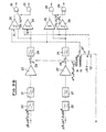
- Figs. 9A to 9C the electronic detection equipment associated with two pairs of probes 1 a -1 b and 1 c- 1 d .
- the mechanical connections are shown in dashed lines, the analog connections in dotted lines and the logical connections in solid lines.
- the entire electronic circuit can be connected by four switches 13 either to the four probes 1a to 1 d , or to four other similar probes 1 ' to 1' d arranged in the same way but in a location outside the straightener. These four other probes are used to calibrate the circuit by scanning a section of bar driven in rotation but fixed in translation and having a well-defined defect.
- An oscillator 14 feeds via power amplifiers 15 one or the other of the two groups of four probes.
- the frequency of oscillator 14 has been adjusted to 100 kHz, which leads to practically purely angular variations of the vector V.
- the voltages V collected at the terminals of each probe, after having been preamplified by a preamplification module incorporated into each probe, are sent to the processing cabinet containing the electronic circuit.
- the signals are then amplified by an amplifier 22 and reach a switch 23.
- the circuit 18 compares the modules r with values corresponding to two predetermined distances minimum d m and maximum d m and outputs four logical pieces of information d a to d d . If the distance of product 2 to the probe concerned is greater than d M , it is considered that this product is absent; if it is less than d m , this corresponds to excessive wear of the protective part 12.
- the passages of one of the pieces of information from to d d from 0 to 1 corresponds to a distance between the product and the probe between d m and d M , that is to say the presence of a bar in front of the probe and a good protection of the latter, and closes the switch 23, which avoids further processing the erratic signals appearing in the no bar. It will be assumed below that the switch 23 is closed.
- the signal After filtering in a high-pass filter 24, the signal approaches the logic part of the electronic circuit arriving at two comparators 25, 26 where it is compared with two thresholds respectively.
- the comparator 25 receives a threshold Y1 and the comparator 26 a threshold of + 15 Volts much higher than the signals that can be received, so that only the first comparator provides output signals.
- the two comparators receive thresholds Y1 and Y2 corresponding to two degrees of severity of the control. The above four thresholds are obtained. by means of a double switch 27 coupled to switches 13.
- each comparator 25, 26, applied to an input of two AND gates 28, 29 respectively, thus provides logic signals representative of disturbing phenomena of amplitude at least equal to a predetermined value.
- the rest of the circuit is used to detect whether or not these are product faults. Indeed. an output signal from the comparators 25, 26 can be generated not only by a metallurgical defect of the type sought, but also by the influence of the ends of the product to be checked on the probes or by a disturbing phenomenon of electrical or mechanical origin.
- the speed of the cylindrical roller 8 is measured with a tachometric dynamo 30 associated with an adjustment potentiometer 30 '.
- V G the linear speed of the product 2.
- the signals leaving registers 36 and 37 are combined, through an OR gate 38, 39 respectively, with the corresponding signals relating to the other two probes 1 c and 1 °, and reach a device 40 for counting, memorizing and commanding marking .
- Various decisions can then be taken as to the fate of the bars checked, depending on the number of faults above the two thresholds, thanks to counters 41, a sorting command 42 and a command to mark the bars 43 connected to the device 40.
- the device 40 also makes it possible to evaluate the dimensions of the defects detected.
- the correlation circuit 33 is intended to eliminate parasitic signals of electrical or mechanical origin. For this, this circuit memorizes each signal received, then on the appearance of a second signal, it checks that it corresponds to the same place on the bar, or to another place located on the same generator. If so, and only in this case, the signal is validated and treated as corresponding to a fault.
- the circuit 33 which is common to the two pairs of probes 1a - 1b and 1c -1 d , comprises a shift register controlled by a natural frequency proportional to the speed of rotation of the bar.
- the factor K 2 incorporates l 'inclination of the rollers, which determines the pitch of the helix advance propeller.
- the passage time of the above-mentioned shift register is equal to the rotation time of the bar 2.
- a device 45 for monitoring the probes which checks the almost simultaneous passage of 0 to 1 and from 1 to 0 of the signals d a to d d .
- This device is linked to appropriate security and alarm devices 46.
- the electrical device of Figs. 9A to 9C includes a certain number of suitable test points making it possible to measure the signals at these points. These test points have not been shown for the sake of clarity.
- each probe may differ from one H.
- the probe may include an additional branch perpendicular to the product 2, the middle branch carrying the two windings 6 and 7.
- the invention applies to the control of metallic products other than round bars such as bars having another shape in section or strips.
- the controlled product can be fixed and the probe (s) mobile so as to scan the entire surface of the product.
- the probe can be mounted on a rotary support to control a round bar moving in translation along the axis of rotation of this support.
- the straightener comprises an upper cylindrical roller 8 and a lower hyperbolic roller 9 rotating in the same direction and whose respective axes XX and YY are horizontal and oblique, oriented in opposite directions, and intersect the vertical plane of symmetry P of the machine in the same transverse vertical plane Q, which is the plane of FIG. 11.
- the machine further comprises two fixed horizontal guide strips 10 and 11.
- the strip 10 which faces the direction of rotation of the hyperbolic roller 9 is only attacked by the ends of the product 2 to be checked, which is a bar round animated by a horizontal scrolling movement following the arrows shown in Figs. 10 and 11, while the current part thereof only comes into contact with the opposite strip 11.
- the probe 1 is embedded in the strip 10 and is protected by an interchangeable part 12. The probe 1 is connected by electrical wires 100 to the electronic circuit described above.
- the tests have shown that the plane Q was not at all the most favorable location for the detection of faults according to the method described with reference to FIGS. 1 to 9C, because when the probe is in this plane or in its vicinity, a strong background noise is obtained, which can reach a level sufficient to prevent discrimination of the signals generated by the metallurgical defects sought.
- the optimal arrangement consists in installing the first probe, or upstream probe, opposite point C.
- the stresses generated by this bending between points B and C are maximum at point A and are added to the compression stresses generated by the tightening of the rollers and to the internal mechanical tensions generated by machining (stretching, peeling and straightening).
- the resulting stresses vary due to the displacement of the bar and generate signals which are added to those generated by the structure, the mechanical vibrations. and any faults.
- the background noise is increased irregularly but all the more important as the stresses are higher.
- point C is the point devoid of bending and compression constraints where the vibration of product 2 is minimal.
Landscapes
- Chemical & Material Sciences (AREA)
- Chemical Kinetics & Catalysis (AREA)
- Electrochemistry (AREA)
- Physics & Mathematics (AREA)
- Health & Medical Sciences (AREA)
- Life Sciences & Earth Sciences (AREA)
- Analytical Chemistry (AREA)
- Biochemistry (AREA)
- General Health & Medical Sciences (AREA)
- General Physics & Mathematics (AREA)
- Immunology (AREA)
- Pathology (AREA)
- Investigating Or Analyzing Materials By The Use Of Magnetic Means (AREA)
Claims (9)
Applications Claiming Priority (4)
| Application Number | Priority Date | Filing Date | Title |
|---|---|---|---|
| FR8024016A FR2493991A1 (fr) | 1980-11-12 | 1980-11-12 | Procede et dispositif de detection par courants de foucault de defauts dans un produit metallique |
| FR8024016 | 1980-11-12 | ||
| FR8103726 | 1981-02-25 | ||
| FR8103726A FR2500632B2 (fr) | 1980-11-12 | 1981-02-25 | Dispositif de detection par courants de foucault de defauts dans un produit metallique |
Publications (2)
| Publication Number | Publication Date |
|---|---|
| EP0052058A1 EP0052058A1 (de) | 1982-05-19 |
| EP0052058B1 true EP0052058B1 (de) | 1986-10-01 |
Family
ID=26222070
Family Applications (1)
| Application Number | Title | Priority Date | Filing Date |
|---|---|---|---|
| EP19810401780 Expired EP0052058B1 (de) | 1980-11-12 | 1981-11-10 | Vorrichtung zum Auffinden von Fehlern in einem metallenen Produkt mittels Wirbelströme |
Country Status (3)
| Country | Link |
|---|---|
| EP (1) | EP0052058B1 (de) |
| DE (1) | DE3175426D1 (de) |
| FR (1) | FR2500632B2 (de) |
Families Citing this family (4)
| Publication number | Priority date | Publication date | Assignee | Title |
|---|---|---|---|---|
| FR2572175A1 (fr) * | 1984-10-24 | 1986-04-25 | Stein Heurtey | Procede et dispositif pour mesurer l'epaisseur de couches metalliques minces deposees sur un support conducteur |
| SE456864B (sv) * | 1986-08-27 | 1988-11-07 | Toernbloms Kvalitetskontroll | Anordning foer att vid virvelstroemsprovning av omagnetiska provobjekt detektera och undertrycka inverkan av stoerande magnetiska omraaden |
| DE102011004167B4 (de) * | 2011-02-15 | 2015-05-13 | Institut Dr. Foerster Gmbh & Co. Kg | Verfahren und Vorrichtung zum automatisierten Richten von langgestrecktem Material |
| CN116429879A (zh) * | 2023-03-15 | 2023-07-14 | 重庆神骥新材料科技有限公司 | 一种微通道平行流管的涡流检测装置及其检测方法 |
Family Cites Families (8)
| Publication number | Priority date | Publication date | Assignee | Title |
|---|---|---|---|---|
| FR1308785A (fr) * | 1961-10-13 | 1962-11-09 | Gkn Group Services Ltd | Perfectionnements apportés aux procédés et appareils pour déceler la présence de défauts dans des solides cohérents électriquement conducteurs |
| GB1200146A (en) * | 1967-08-17 | 1970-07-29 | Friedrich M O Foerster | Measuring magnetic fields |
| US3535625A (en) * | 1968-04-22 | 1970-10-20 | Garrett Corp | Strain and flaw detector |
| US3568485A (en) * | 1968-08-09 | 1971-03-09 | Republic Steel Corp | Method and apparatus for straightening and testing workpieces |
| DE2308446C3 (de) * | 1973-02-21 | 1975-09-25 | Institut Dr. Friedrich Foerster, Pruefgeraetebau, 7410 Reutlingen | Richtmaschine für langgestrecktes, metallisches Richtgut |
| US3916301A (en) * | 1974-05-20 | 1975-10-28 | Republic Steel Corp | Magnetic flaw detection apparatus |
| US4191922A (en) * | 1978-03-14 | 1980-03-04 | Republic Steel Corporation | Electromagnetic flaw detection system and method incorporating improved automatic coil error signal compensation |
| US4287474A (en) * | 1979-02-12 | 1981-09-01 | Fastritsky Viktor S | Method and apparatus for non-destructive quality testing of spot welds |
-
1981
- 1981-02-25 FR FR8103726A patent/FR2500632B2/fr not_active Expired
- 1981-11-10 EP EP19810401780 patent/EP0052058B1/de not_active Expired
- 1981-11-10 DE DE8181401780T patent/DE3175426D1/de not_active Expired
Also Published As
| Publication number | Publication date |
|---|---|
| FR2500632B2 (fr) | 1987-12-24 |
| DE3175426D1 (en) | 1986-11-06 |
| EP0052058A1 (de) | 1982-05-19 |
| FR2500632A2 (fr) | 1982-08-27 |
Similar Documents
| Publication | Publication Date | Title |
|---|---|---|
| EP0195794B1 (de) | Wirbelstromverfahren zur feststellung von oberflächenfehlern und vorrichtung zum durchführen dieses verfahrens | |
| EP2035822B1 (de) | Zerstörungsfreies testen von giessereiprodukten mittels ultraschall | |
| EP0021893B1 (de) | Verfahren und Vorrichtung zur Wirbelstromprüfung metallischer Produkte und Anwendung der Vorrichtung und des Verfahrens | |
| FR2513413A1 (fr) | Appareil de selection de pieces de monnaie | |
| FR2570500A1 (fr) | Procede et dispositif de detection de defauts typiques sur un produit en defilement, notamment pour la detection de criques sur une brame | |
| FR2541772A1 (fr) | Procede et dispositif pour l'examen non destructif de jonctions rivetees ou analogues au moyen d'une sonde a courants de foucault | |
| EP0290513B1 (de) | Verfahren zum feststellen der variationen der wandstärke eines elektrisch leitenden körpers | |
| FR2689273A1 (fr) | Appareil de traitement de signaux pour évaluation de données de contrôle. | |
| EP0052058B1 (de) | Vorrichtung zum Auffinden von Fehlern in einem metallenen Produkt mittels Wirbelströme | |
| FR2623614A1 (fr) | Procede et dispositif pour la detection de variations de sections dans un objet de grande longueur, en particulier un cable | |
| EP0236841B1 (de) | Ausdehnungsmessverfahren für ein langes Element mit kleiner transversaler Dimension aus magnetisierbarem Metall und Vorrichtung zur Anwendung dieses Verfahrens | |
| FR2493991A1 (fr) | Procede et dispositif de detection par courants de foucault de defauts dans un produit metallique | |
| FR2743917A1 (fr) | Dispositif selecteur d'objets, notamment pieces de monnaie | |
| FR2684441A1 (fr) | Rouleau mesureur de planeite d'une bande fabriquee en continu. | |
| EP0468905A1 (de) | Vorrichtung und Verfahren zur Qualitätskontrolle von Metallrohren während des Heisswalzens durch Wirbelstrom | |
| EP0061956B1 (de) | Verfahren zur wirbelstromzerstörungsfreien Prüfung unabhängig von dem Abstand der Sonden relativ zu dem Probenstück und Vorrichtung zur Ausübung des Verfahrens | |
| EP1167917A1 (de) | Verfahren zur Dickenmessung von Hohlflügelwand | |
| FR2466772A1 (fr) | Procede et dispositif pour la verification non destructive de tubes et de barres au moyen d'ultrasons | |
| EP0505421B1 (de) | Verfahren zur detektion und dimensionierung von fehlern in netzförmigen metallischen strukturen | |
| Goebbels et al. | Automation of surface defect detection and evaluation | |
| FR2817352A1 (fr) | Dispositif de controle de conformite de reseaux de pistes conductrices pour ecrans plats | |
| CA1183210A (fr) | Procede de detection de defauts d'un produit metallique par courants de foucault | |
| JPH09178668A (ja) | 表面検査装置 | |
| FR2678384A1 (fr) | Dispositif electromagnetique pour la detection de defauts dans un cable. | |
| FR2762157A1 (fr) | Procede et dispositif pour examiner l'etat d'isolation des toles d'un empilement dans une machine electrique |
Legal Events
| Date | Code | Title | Description |
|---|---|---|---|
| PUAI | Public reference made under article 153(3) epc to a published international application that has entered the european phase |
Free format text: ORIGINAL CODE: 0009012 |
|
| AK | Designated contracting states |
Designated state(s): DE GB IT SE |
|
| 17P | Request for examination filed |
Effective date: 19821116 |
|
| RAP1 | Party data changed (applicant data changed or rights of an application transferred) |
Owner name: INTERCONTROLE SOCIETE DITE: |
|
| GRAA | (expected) grant |
Free format text: ORIGINAL CODE: 0009210 |
|
| ITF | It: translation for a ep patent filed | ||
| AK | Designated contracting states |
Kind code of ref document: B1 Designated state(s): DE GB IT SE |
|
| REF | Corresponds to: |
Ref document number: 3175426 Country of ref document: DE Date of ref document: 19861106 |
|
| PLBE | No opposition filed within time limit |
Free format text: ORIGINAL CODE: 0009261 |
|
| STAA | Information on the status of an ep patent application or granted ep patent |
Free format text: STATUS: NO OPPOSITION FILED WITHIN TIME LIMIT |
|
| 26N | No opposition filed | ||
| PG25 | Lapsed in a contracting state [announced via postgrant information from national office to epo] |
Ref country code: SE Effective date: 19871111 |
|
| GBPC | Gb: european patent ceased through non-payment of renewal fee | ||
| PG25 | Lapsed in a contracting state [announced via postgrant information from national office to epo] |
Ref country code: DE Effective date: 19880802 |
|
| PG25 | Lapsed in a contracting state [announced via postgrant information from national office to epo] |
Ref country code: GB Effective date: 19881118 |
|
| EUG | Se: european patent has lapsed |
Ref document number: 81401780.2 Effective date: 19880913 |