EP0052081A1 - Système de construction par blocs d'une installation de chauffage - Google Patents
Système de construction par blocs d'une installation de chauffage Download PDFInfo
- Publication number
- EP0052081A1 EP0052081A1 EP81810451A EP81810451A EP0052081A1 EP 0052081 A1 EP0052081 A1 EP 0052081A1 EP 81810451 A EP81810451 A EP 81810451A EP 81810451 A EP81810451 A EP 81810451A EP 0052081 A1 EP0052081 A1 EP 0052081A1
- Authority
- EP
- European Patent Office
- Prior art keywords
- groups
- modular system
- connection
- group
- prefabricated
- Prior art date
- Legal status (The legal status is an assumption and is not a legal conclusion. Google has not performed a legal analysis and makes no representation as to the accuracy of the status listed.)
- Withdrawn
Links
- 238000010438 heat treatment Methods 0.000 title claims abstract description 25
- 238000010276 construction Methods 0.000 title abstract description 4
- 230000002093 peripheral effect Effects 0.000 claims abstract description 10
- 239000000463 material Substances 0.000 abstract description 6
- 230000006978 adaptation Effects 0.000 abstract description 4
- 238000010586 diagram Methods 0.000 description 2
- 238000005553 drilling Methods 0.000 description 1
- 230000002349 favourable effect Effects 0.000 description 1
- 238000009434 installation Methods 0.000 description 1
- 238000009413 insulation Methods 0.000 description 1
- 239000012774 insulation material Substances 0.000 description 1
- JEIPFZHSYJVQDO-UHFFFAOYSA-N iron(III) oxide Inorganic materials O=[Fe]O[Fe]=O JEIPFZHSYJVQDO-UHFFFAOYSA-N 0.000 description 1
- 239000005022 packaging material Substances 0.000 description 1
- 238000009417 prefabrication Methods 0.000 description 1
- 239000003566 sealing material Substances 0.000 description 1
- 230000007704 transition Effects 0.000 description 1
- XLYOFNOQVPJJNP-UHFFFAOYSA-N water Substances O XLYOFNOQVPJJNP-UHFFFAOYSA-N 0.000 description 1
Images

Classifications
-
- F—MECHANICAL ENGINEERING; LIGHTING; HEATING; WEAPONS; BLASTING
- F24—HEATING; RANGES; VENTILATING
- F24D—DOMESTIC- OR SPACE-HEATING SYSTEMS, e.g. CENTRAL HEATING SYSTEMS; DOMESTIC HOT-WATER SUPPLY SYSTEMS; ELEMENTS OR COMPONENTS THEREFOR
- F24D3/00—Hot-water central heating systems
-
- F—MECHANICAL ENGINEERING; LIGHTING; HEATING; WEAPONS; BLASTING
- F24—HEATING; RANGES; VENTILATING
- F24D—DOMESTIC- OR SPACE-HEATING SYSTEMS, e.g. CENTRAL HEATING SYSTEMS; DOMESTIC HOT-WATER SUPPLY SYSTEMS; ELEMENTS OR COMPONENTS THEREFOR
- F24D3/00—Hot-water central heating systems
- F24D3/10—Feed-line arrangements, e.g. providing for heat-accumulator tanks, expansion tanks ; Hydraulic components of a central heating system
Definitions
- the present invention relates to a modular system for creating a heating system from basic elements.
- the present invention takes up the idea of standardizing and prefabricating units for the creation of a heating system, but it has the task of combining the entire heating system into different standardized groups and thus the input to facilitate the described work in the design office and on the construction site.
- the elements are prefabricated into groups, all of which have a predetermined grid of fixed connection distances between the supply and return pipes and can be connected directly to one another without adaptation.
- connection from the connection groups to the peripheral heating elements and / or groups can take place by means of flexible hoses or plastic pipes.
- FIG. 1 If you want to use the modular system according to the invention to create a heating system, it is sufficient to outline a block diagram of the heating system, as shown in FIG. 1.
- the heating specialist determines the capacity of the heating system resulting from the building object and orders the corresponding boiler 1, possibly with direct hot water preparation2. He can compile all other parts of the heating system using a catalog. However, this is made considerably easier for him, since he no longer has to search out all of the individual parts as before, but can simply order the required groups 3 - 8, which can be connected to one another without adjustment.
- the individually prefabricated groups 3 - 8 all have a predetermined grid of defined connection distances between the associated, parallel running supply and return pipes. In the Figure 1, the individual groups are symbolized by blocks.
- the distance of the connections that go horizontally is always A here, while the distance of the vertically outgoing connections is always B.
- the individual groups can thus be linked together as required.
- Peripheral groups 8 and heating elements 9 are also attached without adaptation, in that the rigid groups are connected to them by flexible connections in the form of tubes 10.
- the peripheral groups do not necessarily have to have the same grid of connection distances as the other groups.
- block 3 is intended to symbolize a connection group, block 4 a switchover group, block 5 "a special group, block 6 a distribution group and block 7 a safety group.
- Hoses 10 lead from the distribution group 6 to the peripheral groups 8 and / or heating elements 9
- Such a peripheral group can be, for example, a floor distribution unit, and the security group 7 can also be configured or arranged peripherally with a hose connection.
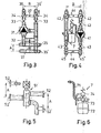
- FIGS. 2-6 Exemplary embodiments of groups 3-8 are shown in FIGS. 2-6 and described below. There are no limits to the selection of the basic elements for prefabricating the groups.
- connection group 3 is recorded in FIG. 3.
- This is a connection group with automatic outside temperature control.
- the main element of this group is a mixer 31 with automatic outside temperature control and manual control with a combined circulation pump, which are brought onto the market by the Saurer company, for example, under the name PM 16-2.
- Other elements of the group are a short circuit 32 with a ball valve, two sleeve slides 33, two thermometers 34 and two drain cocks.
- the two lower, parallel flow and return pipe parts 35, 35 ' have the predetermined distance A and can be used for both left and right connection.
- the pipes 36, 36 ' which also run in parallel, have a different predetermined distance B.
- the predetermined distances A, B which reappear in all central groups, enable the adjustment-free Connect with any other group.
- the groups which are designed with connections with an internal thread, treated with rust protection and packed in cardboard boxes, also contain all the assembly material. Because the groups are already supplied with fixed wall fastenings 37, the heating technician can work quickly without losing time. This is also guaranteed by the above-mentioned assembly material, which includes dowels and screws, safety sleeves with plugs and seals, insulation and sealing material, a drilling jig, etc. Of course, each group contains an assortment of assembly material that is especially suitable for this.
- Special groups are units that are required to connect special energy generation systems. They comprise at least one of their own circulation pumps and can be coupled to a security group 7, as shown in FIG. 4.
- transition or assembly groups (not shown) that allow the connection of vertical to horizontal pipes.
- Such a group includes elbows and connection material.
- switch groups For switching from an energy carrier system to another is used by switch groups as shown in FIG. 5.
- the drawn unit is used to switch from; a heat pump on the boiler.
- the connections 52, 52 'again have the predetermined distance A.
- the safety group is hardly bound in its placement, since today's heating systems are always closed systems. As a result, the security group is placed in the most favorable place according to the structural conditions. This location can be central or peripheral. Depending on the situation, the connection is made via a rigid pipe or - as shown in FIG. 6 - via a flexible hose 71.
- the other elements of the safety group are an expansion vessel 72, a manometer 73 and a safety valve 74.
- the kit is supplemented by distribution groups 6.
- a floor distribution unit for floor heating with two circuits is shown. Since this is a peripheral group the connection distance between the forward 81 and the return 82 does not necessarily have to be the same as that of the previously described central groups, since the connection to the central groups is always achieved here by means of flexible hoses 10. This group is also provided with fixed wall mounting elements 83 for assembly.
Landscapes
- Engineering & Computer Science (AREA)
- Physics & Mathematics (AREA)
- Thermal Sciences (AREA)
- Chemical & Material Sciences (AREA)
- Combustion & Propulsion (AREA)
- Mechanical Engineering (AREA)
- General Engineering & Computer Science (AREA)
- Steam Or Hot-Water Central Heating Systems (AREA)
Applications Claiming Priority (2)
| Application Number | Priority Date | Filing Date | Title |
|---|---|---|---|
| CH838680 | 1980-11-12 | ||
| CH8386/80 | 1980-11-12 |
Publications (1)
| Publication Number | Publication Date |
|---|---|
| EP0052081A1 true EP0052081A1 (fr) | 1982-05-19 |
Family
ID=4339523
Family Applications (1)
| Application Number | Title | Priority Date | Filing Date |
|---|---|---|---|
| EP81810451A Withdrawn EP0052081A1 (fr) | 1980-11-12 | 1981-11-12 | Système de construction par blocs d'une installation de chauffage |
Country Status (2)
| Country | Link |
|---|---|
| EP (1) | EP0052081A1 (fr) |
| DE (2) | DE8132052U1 (fr) |
Cited By (5)
| Publication number | Priority date | Publication date | Assignee | Title |
|---|---|---|---|---|
| FR2500592A1 (fr) * | 1981-02-25 | 1982-08-27 | Lhote Jean | Dispositif sous forme de chassis premonte, permettant de relier tres rapidement un appareil de production de chaleur a un reseau d'utilisation sans outillage specifique |
| EP0222040A3 (fr) * | 1985-11-11 | 1988-03-30 | IWK Regler und Kompensatoren GmbH | Installation de la technique du chauffage |
| EP1031795A3 (fr) * | 1999-02-24 | 2002-11-20 | Fontecal S.p.A. | Ensemble modulaire hydraulique |
| EP2320148A3 (fr) * | 2009-11-07 | 2014-12-24 | PAW GmbH & Co. KG | Installation thermique solaire dotée d'au moins un collecteur pour la chaleur solaire |
| NL2014236B1 (nl) * | 2015-02-05 | 2016-10-12 | J H Chardet Loodgietersbedrijf | Geïntegreerd tussenstuk voor een vloerverwarmingsinstallatie. |
Families Citing this family (2)
| Publication number | Priority date | Publication date | Assignee | Title |
|---|---|---|---|---|
| CH659719A5 (de) * | 1983-01-06 | 1987-02-13 | Stramax Ag | Regelarmatur fuer eine flaechenklimatisiervorrichtung. |
| DE19637575B4 (de) * | 1996-09-14 | 2005-02-17 | Helmut Bälz GmbH | Verteilerstation für ein Heizungssystem |
Citations (4)
| Publication number | Priority date | Publication date | Assignee | Title |
|---|---|---|---|---|
| DE2038991A1 (de) * | 1970-08-05 | 1972-02-10 | Pruefling Gerhard Dipl Ing | Rohrleitungsanordnung fuer Warmwasserzentralheizungsanlagen |
| DE2411998A1 (de) * | 1973-03-14 | 1974-09-19 | Alois Schwarz | Bausatz von verbindungsarmaturen |
| CH573569A5 (fr) * | 1974-01-16 | 1976-03-15 | Tredi Holding Ag | |
| DE2803458A1 (de) * | 1978-01-27 | 1979-08-02 | Uwe Hansen | Vorrichtung zur solaren erwaermung eines waermetraegermediums |
-
1981
- 1981-11-03 DE DE19818132052 patent/DE8132052U1/de not_active Expired
- 1981-11-03 DE DE19813143497 patent/DE3143497A1/de not_active Withdrawn
- 1981-11-12 EP EP81810451A patent/EP0052081A1/fr not_active Withdrawn
Patent Citations (4)
| Publication number | Priority date | Publication date | Assignee | Title |
|---|---|---|---|---|
| DE2038991A1 (de) * | 1970-08-05 | 1972-02-10 | Pruefling Gerhard Dipl Ing | Rohrleitungsanordnung fuer Warmwasserzentralheizungsanlagen |
| DE2411998A1 (de) * | 1973-03-14 | 1974-09-19 | Alois Schwarz | Bausatz von verbindungsarmaturen |
| CH573569A5 (fr) * | 1974-01-16 | 1976-03-15 | Tredi Holding Ag | |
| DE2803458A1 (de) * | 1978-01-27 | 1979-08-02 | Uwe Hansen | Vorrichtung zur solaren erwaermung eines waermetraegermediums |
Cited By (5)
| Publication number | Priority date | Publication date | Assignee | Title |
|---|---|---|---|---|
| FR2500592A1 (fr) * | 1981-02-25 | 1982-08-27 | Lhote Jean | Dispositif sous forme de chassis premonte, permettant de relier tres rapidement un appareil de production de chaleur a un reseau d'utilisation sans outillage specifique |
| EP0222040A3 (fr) * | 1985-11-11 | 1988-03-30 | IWK Regler und Kompensatoren GmbH | Installation de la technique du chauffage |
| EP1031795A3 (fr) * | 1999-02-24 | 2002-11-20 | Fontecal S.p.A. | Ensemble modulaire hydraulique |
| EP2320148A3 (fr) * | 2009-11-07 | 2014-12-24 | PAW GmbH & Co. KG | Installation thermique solaire dotée d'au moins un collecteur pour la chaleur solaire |
| NL2014236B1 (nl) * | 2015-02-05 | 2016-10-12 | J H Chardet Loodgietersbedrijf | Geïntegreerd tussenstuk voor een vloerverwarmingsinstallatie. |
Also Published As
| Publication number | Publication date |
|---|---|
| DE8132052U1 (de) | 1983-04-07 |
| DE3143497A1 (de) | 1982-09-02 |
Similar Documents
| Publication | Publication Date | Title |
|---|---|---|
| DE60007116T2 (de) | Baueinheit für eine sammelleitung eines versorgungsnetzes und befestigungssystem für solche baueinheiten | |
| DE1604205A1 (de) | Klimaanlage | |
| DE2747813B2 (de) | Anlage zur Raumheizung und Brauchwasserbereitung | |
| EP0092032B1 (fr) | Dispositif pour transférer la chaleur d'un conduit de distribution à un consommateur | |
| EP0052081A1 (fr) | Système de construction par blocs d'une installation de chauffage | |
| DE3416574A1 (de) | Modulare steuer- und pumpeneinheit fuer heizzentralen und dergleichen | |
| EP0318536B1 (fr) | Dispositif de transfert de chaleur a distance | |
| DE1526995B1 (de) | Atomkraftanlage | |
| DE102011106022A1 (de) | Warmwassererzeugungs-, Speicher- und Abgabevorrichtung | |
| DE4015139C2 (de) | Verfahren zur Steuerung einer Wasserheizungsanlage | |
| DE2826177A1 (de) | Verfahren und waermeuebertrager zur erwaermung von heizungs- und brauchwasser | |
| EP0222040A2 (fr) | Installation de la technique du chauffage | |
| DE2704601C2 (de) | Warmwasserheizungsanlage mit thermostatisch geregeltem Wannwasservorlauf | |
| DE2625405C2 (fr) | ||
| DE4408407C2 (de) | Wärmetauscher-Element zur kalorischen Anbindung eines Niedertemperatur-Heizkreislaufes an einen Wasser-Radiatorkreislauf | |
| DE2625449C3 (fr) | ||
| DE2542547A1 (de) | Steuerungsverfahren fuer fussbodenheizungen sowie stelleinrichtung zur durchfuehrung des verfahrens | |
| DE1955505C3 (de) | Schwimmbeckenwasser-Reinigungsanlage mit kesseiförmigem Ausgleichbehälter | |
| DE8206002U1 (de) | Vorrichtung zum erwaermen von brauchwasser unter ausnutzng der waerme eines fluids | |
| DE968502C (de) | Heizverfahren und zugehoerige Heisswasser-Pumpenheizungsanlage | |
| DE29722530U1 (de) | Heizungssteuerungsanlage | |
| DE2803600A1 (de) | Sammler fuer eine zentralheizungsanlage | |
| DE2038991A1 (de) | Rohrleitungsanordnung fuer Warmwasserzentralheizungsanlagen | |
| EP0058132A2 (fr) | Installation de chauffage | |
| DE1779911A1 (de) | Sammelheizungsanlage |
Legal Events
| Date | Code | Title | Description |
|---|---|---|---|
| PUAI | Public reference made under article 153(3) epc to a published international application that has entered the european phase |
Free format text: ORIGINAL CODE: 0009012 |
|
| AK | Designated contracting states |
Designated state(s): AT BE DE FR GB IT LU NL SE |
|
| 17P | Request for examination filed |
Effective date: 19821007 |
|
| STAA | Information on the status of an ep patent application or granted ep patent |
Free format text: STATUS: THE APPLICATION IS DEEMED TO BE WITHDRAWN |
|
| 18D | Application deemed to be withdrawn |
Effective date: 19840307 |
|
| RIN1 | Information on inventor provided before grant (corrected) |
Inventor name: FRICK, ALVARO, ING. DIPL. |