EP0052090B1 - Verfahren zum Bilden einer abgedichteten Kabeldurchführung - Google Patents
Verfahren zum Bilden einer abgedichteten Kabeldurchführung Download PDFInfo
- Publication number
- EP0052090B1 EP0052090B1 EP19810850215 EP81850215A EP0052090B1 EP 0052090 B1 EP0052090 B1 EP 0052090B1 EP 19810850215 EP19810850215 EP 19810850215 EP 81850215 A EP81850215 A EP 81850215A EP 0052090 B1 EP0052090 B1 EP 0052090B1
- Authority
- EP
- European Patent Office
- Prior art keywords
- cable
- cables
- opening
- flange
- lead
- Prior art date
- Legal status (The legal status is an assumption and is not a legal conclusion. Google has not performed a legal analysis and makes no representation as to the accuracy of the status listed.)
- Expired
Links
- 238000000034 method Methods 0.000 title claims description 13
- 238000012856 packing Methods 0.000 claims description 10
- 150000001875 compounds Chemical class 0.000 claims description 3
- 238000003780 insertion Methods 0.000 claims description 3
- 230000037431 insertion Effects 0.000 claims description 3
- 230000004927 fusion Effects 0.000 claims description 2
- 238000004804 winding Methods 0.000 claims description 2
- 230000000694 effects Effects 0.000 description 3
- 210000004907 gland Anatomy 0.000 description 3
- 238000007789 sealing Methods 0.000 description 2
- ONBQEOIKXPHGMB-VBSBHUPXSA-N 1-[2-[(2s,3r,4s,5r)-3,4-dihydroxy-5-(hydroxymethyl)oxolan-2-yl]oxy-4,6-dihydroxyphenyl]-3-(4-hydroxyphenyl)propan-1-one Chemical compound O[C@@H]1[C@H](O)[C@@H](CO)O[C@H]1OC1=CC(O)=CC(O)=C1C(=O)CCC1=CC=C(O)C=C1 ONBQEOIKXPHGMB-VBSBHUPXSA-N 0.000 description 1
- 230000000712 assembly Effects 0.000 description 1
- 238000000429 assembly Methods 0.000 description 1
- 229940126142 compound 16 Drugs 0.000 description 1
- 239000000428 dust Substances 0.000 description 1
- 239000000945 filler Substances 0.000 description 1
- 239000006260 foam Substances 0.000 description 1
- 229910052500 inorganic mineral Inorganic materials 0.000 description 1
- 239000000463 material Substances 0.000 description 1
- 239000011707 mineral Substances 0.000 description 1
- 238000012986 modification Methods 0.000 description 1
- 230000004048 modification Effects 0.000 description 1
- 239000000843 powder Substances 0.000 description 1
- 230000000284 resting effect Effects 0.000 description 1
- 230000000717 retained effect Effects 0.000 description 1
Images

Classifications
-
- H—ELECTRICITY
- H02—GENERATION; CONVERSION OR DISTRIBUTION OF ELECTRIC POWER
- H02G—INSTALLATION OF ELECTRIC CABLES OR LINES, OR OF COMBINED OPTICAL AND ELECTRIC CABLES OR LINES
- H02G3/00—Installations of electric cables or lines or protective tubing therefor in or on buildings, equivalent structures or vehicles
- H02G3/02—Details
- H02G3/06—Joints for connecting lengths of protective tubing or channels, to each other or to casings, e.g. to distribution boxes; Ensuring electrical continuity in the joint
- H02G3/0616—Joints for connecting tubing to casing
-
- H—ELECTRICITY
- H02—GENERATION; CONVERSION OR DISTRIBUTION OF ELECTRIC POWER
- H02G—INSTALLATION OF ELECTRIC CABLES OR LINES, OR OF COMBINED OPTICAL AND ELECTRIC CABLES OR LINES
- H02G3/00—Installations of electric cables or lines or protective tubing therefor in or on buildings, equivalent structures or vehicles
- H02G3/22—Installations of cables or lines through walls, floors or ceilings, e.g. into buildings
Definitions
- the subject invention concerns a method for use in connecting electric cables in e.g. cable terminal boxes and the like so as to arrange the cables in a tight-fitting manner through the opening in the box.
- the cable lead-through opening into the terminal box must be tight to prevent moisture and dust from entering the box. It is further desirable that the cables are protected against wear and friction at the edges of the lead-through opening and that the cables are retained securely at the lead-through opening to prevent any tensional stress that is exerted on the cables from being transferred to the cable-junction means inside the box.
- rubber possesses a number of desirable properties, such as elasticity and insulating capacity, in addition to which it is comparatively durable.
- desirable properties such as elasticity and insulating capacity
- the rubber material is difficult to work and shape under field conditions. It is both complicated and time-consuming to adapt the blocks of rubber to fit bundles of cables of different make-up. For this reason, problems of leaking inlets easily arise.
- the purpose of the subject invention is to provide an assembly method by means of which cables may be connected in cable terminal boxes in a more simple and rapid manner than has hitherto been possible while at the same time giving an improved end result.
- the invention concerns a method for use in connecting electric cables in cable terminal boxes, of providing a sealed cable lead-through into the box, according to which an attachment frame is initially applied against the terminal box around a cable lead-through opening therein, the attachment frame being provided with a bearing flange which projects transversely relative to the frame, and with two lateral flanges positioned above the bearing flange at an angle thereto, whereafter the electric cables are inserted through the opening, and positioning gauge blocks of rubber, if needed after having been size-fitted through cutting, adjacent and on top of one another on either side of the bundle of cables thus formed between the cable bundle and the adjacent side flange, and at least one packing piece of rubber being applied on top of the bundle of cables so as to extend from one lateral flange to the opposite lateral flange, in abutment against the rubber gauge blocks, and finally a top piece being applied above the packing piece so as to exert a pressure thereon, and being secured to the attachment frame.
- the method according to the invention is characterised in that prior to insertion of a cable through the cable lead-through opening in the terminal box to connect said cable thereto, layers of vulcanizing tape are wound onto that portion of each cable that in assembled position will be positioned immediately outside said opening, said vulcanizing tape consisting of a deformable rubber compound of a kind effecting fusion of the discrete tape winding layers without supply of heat, and in that the cables are thereafter inserted through the lead-through opening with the vulcanizing tapes positioned in contacting relationship with one another and with said bearing flange, whereafter the gauge blocks and the packing piece or pieces are applied so as to fill up the spaces between the lateral flanges and the vulcanizing tapes, whereafter said top piece is applied in position.
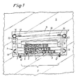
- Fig. 1 illustrates an attachment frame 1 having an inlet or lead-through opening 2 for insertion of flat cables 3 and round cables 4 of different dimensions into a terminal box 5 (suggested only).
- the attachment frame 1 is provided with a bearing flange 6 forming the support face on which the cables 3, 4 are positioned and having apertures 7 therein to accommodate lashing wires, and with lateral flanges 8, one on either side of the cable lead-through opening 2.
- a top piece 9 is provided with a clamping flange 10 and a support flange 11.
- the top piece 9 is designed to be secured to the attachment frame 1 by means of two bolts 12 with the aid of tensioning nuts 12', which are screwed tight against the lower face of the bearing flange 6.
- Oval-shaped apertures 13 allow the top piece to be secured relative to the attachment frame 1 by means of bolts 14, the latter serving to secure the attachment frame 1 to the terminal box 5 with the aid of two apertures 15 in the frame so as to cover the lead-through opening therein.
- the attachment frame 1 is applied over the lead-through aperture of the box 5 and secured by means of two bolts 14 that pass through the two lower apertures 15 in the attachment frame.
- the attachment frame 1 is applied over the lead-through aperture of the box 5 and secured by means of two bolts 14 that pass through the two lower apertures 15 in the attachment frame.
- the widest ones of the flat cables 3 are chosen for the position at the bottom of the attachment frame 1.
- Onto each cable 3 is wound a vulcanizing tape 16 of known type and possessing the characteristic of fusing into a homogeneous mass after a number of hours without heat having to be supplied.
- the cables with the tape thus wound on are placed with the vulcanizing compound abutting against the bearing flange 6 in the centre of the lead-through opening 2.
- the equipment also comprises a number of gauge blocks 17 and packing pieces 18 of rubber in which notches are formed allowing passage-through of the bolts 12.
- the gauge blocks 17 have approximately the same width dimensions as the flange portions 6, 8 and 10 and a height dimension that divides the lead-through opening into several levels or storeys.
- the packing pieces 18 have a length that corresponds to the distance between the two lateral flanges 8 whereas each gauge block 17 is somewhat shorter than half the distance between the two lateral flanges 8.
- Two of the gauge blocks 17 are shortened with the aid of a cutting tool to a length fitting and filling out completely the lateral gap on either side of the cables 3 and the adjacent lateral flange 8.
- Vulcanizing tape is then wound onto the next layer of cables which are positioned on top of the first cable layer.
- Another two gauge blocks 17 are cut to the desired length and positioned on top of the first ones, which are resting on the bearing flange 6, and one continues in this manner until all cables are mounted in the inlet or lead-through opening.
- One or several packing pieces 18 are then positioned on top of the uppermost layer of cables and gauge blocks 17, depending on the total height of the latter, for the purpose of covering the entire lead-through opening 2 with some margin.
- Further vulcanizing tape 16 can be used for the same purpose to achieve the desired height.
- the top piece 9 is applied so as to ensure that the bolts 12 pass through the clamping flange 10, the packing pieces 18, the gauge blocks 17 and the bearing flange 6.
- the through-bolts 12 are tightened, sufficient clamping effect is achieved between the four flange portions 6, 9, 10 and the support flange 11 to ensure that a safe and close-fitting gland is obtained, as illustrated in Fig. 1.
- Further vulcanizing tapes may be used between the gauge blocks when the latter are assembled.
- round cables 4 it is possible to use the vulcanizing tape in the manner shown in Fig. 2 to give the cable a rectangular cross-sectional shape or to give several round cables a flat-section configuration.
- the method in accordance with the invention makes it possible to form a safe and efficient seal rapidly and with simple means. It may be adapted to flat-shaped as well as round cables and combinations thereof. The fitter need not bring along large number of gauge blocks of varying configurations and dimensions.
- the assembly method is applicable in vertical and as well as horizontal assemblies. Owing to the arrangement of the top piece 9, which is designed to exert a pressure transversely against the seal in the lead-through opening, the clamping effect is improved over the axial pressure found in the prior-art devices described above.
- the invention is not limited to the embodiment described in the aforegoing but several modifications are possible within the scope of the appended claims.
- the method is applicable to other types of attachment means having differently shaped flange portions and wherein the securement or locking of the top piece 9 relative to the attachment frame 1 is effected by means different from those used in the attachment frame of the described embodiment.
Landscapes
- Engineering & Computer Science (AREA)
- Architecture (AREA)
- Civil Engineering (AREA)
- Structural Engineering (AREA)
- Cable Accessories (AREA)
- Processing Of Terminals (AREA)
Claims (2)
Applications Claiming Priority (2)
| Application Number | Priority Date | Filing Date | Title |
|---|---|---|---|
| SE8007935 | 1980-11-12 | ||
| SE8007935A SE8007935L (sv) | 1980-11-12 | 1980-11-12 | Sett att astadkomma en tetslutande kabelgenomforing |
Publications (3)
| Publication Number | Publication Date |
|---|---|
| EP0052090A2 EP0052090A2 (de) | 1982-05-19 |
| EP0052090A3 EP0052090A3 (en) | 1983-01-26 |
| EP0052090B1 true EP0052090B1 (de) | 1986-03-05 |
Family
ID=20342219
Family Applications (1)
| Application Number | Title | Priority Date | Filing Date |
|---|---|---|---|
| EP19810850215 Expired EP0052090B1 (de) | 1980-11-12 | 1981-11-12 | Verfahren zum Bilden einer abgedichteten Kabeldurchführung |
Country Status (3)
| Country | Link |
|---|---|
| EP (1) | EP0052090B1 (de) |
| DE (1) | DE3174005D1 (de) |
| SE (1) | SE8007935L (de) |
Families Citing this family (4)
| Publication number | Priority date | Publication date | Assignee | Title |
|---|---|---|---|---|
| DE69502670T2 (de) * | 1994-07-21 | 1998-11-26 | Chemical Research Technology, Sussex, Wis. | Verfahren zur kontinuierlichen Herstellung eines Lackes |
| SE520363C2 (sv) | 2001-12-14 | 2003-07-01 | Roxtec Int Ab | Genomföringsanordning för genomföring av långsträckt ledning genom en öppning i en vägg |
| SE526574C2 (sv) * | 2003-06-17 | 2005-10-11 | Roxtec Ab | Modul och ram för kabelgenomföringar eller liknande |
| CN105042198B (zh) * | 2015-07-10 | 2017-06-16 | 中车南京浦镇车辆有限公司 | 一种地铁车辆引上线孔的密封结构及密封方法 |
Family Cites Families (3)
| Publication number | Priority date | Publication date | Assignee | Title |
|---|---|---|---|---|
| CH179221A (de) * | 1934-11-14 | 1935-08-31 | Helbock Karl | Einrichtung zur Einführung von Kabeln in Häuser. |
| DE2524113C3 (de) * | 1975-05-30 | 1980-05-29 | Gerhard 6954 Hassmersheim Staudt | Verfahren zum Verschotten von elektrischen Leitungen oder Kabeln in Wand- oder Deckendurchführungen von Gebäuden |
| US4207429A (en) * | 1978-09-20 | 1980-06-10 | Plymouth Rubber Company, Inc. | Cable splicing technique |
-
1980
- 1980-11-12 SE SE8007935A patent/SE8007935L/ unknown
-
1981
- 1981-11-12 DE DE8181850215T patent/DE3174005D1/de not_active Expired
- 1981-11-12 EP EP19810850215 patent/EP0052090B1/de not_active Expired
Also Published As
| Publication number | Publication date |
|---|---|
| SE8007935L (sv) | 1982-05-13 |
| EP0052090A3 (en) | 1983-01-26 |
| EP0052090A2 (de) | 1982-05-19 |
| DE3174005D1 (en) | 1986-04-10 |
Similar Documents
| Publication | Publication Date | Title |
|---|---|---|
| US4963700A (en) | Closure arrangements for electrical splices | |
| US4451696A (en) | Toolless splice sealant device | |
| US5382756A (en) | Encapsulation closure for cables | |
| US3692926A (en) | Alignable end seals for a splice case | |
| US5401906A (en) | Water resistant supplementary joint cover for an electrical busway | |
| US4721830A (en) | Cable enclosure | |
| US5434945A (en) | Protective shell for cable connection module | |
| US4358634A (en) | Protective cover for use in sealed cable splices | |
| US4262167A (en) | Cable splice case | |
| US4935582A (en) | Splice enclosure for electrical wires | |
| US4692564A (en) | Cable support system | |
| US4341922A (en) | Strain-relief brace for cable splice case | |
| JPH05276619A (ja) | ケーブルスプライス装置 | |
| US3796823A (en) | Splice case with gas tight seal | |
| US3728467A (en) | Buried-type splice case | |
| US3775204A (en) | Method of gasketing the mating surface of housing parts and entryways for electrical conductors | |
| US3576937A (en) | Underground rigid connector housing seal | |
| KR100616731B1 (ko) | 클로우져를 위한 실 및 실을 포함하는 클로우져 | |
| US5313018A (en) | Cable sleeve composed of a longitudinally-divided housing | |
| US4554401A (en) | Buried cable splice closure | |
| EP0052090A2 (de) | Verfahren zum Bilden einer abgedichteten Kabeldurchführung | |
| US4409430A (en) | Multiple joint box | |
| US5266743A (en) | Seal for an electric cable having an insulating sheath wrapped by exposed electrical conductors and method for sealing the electric cable to a surrounding enclosure | |
| CA2222256C (en) | Cable connection protecting device | |
| RU205017U1 (ru) | Устройство для герметизации кабельного ввода |
Legal Events
| Date | Code | Title | Description |
|---|---|---|---|
| PUAI | Public reference made under article 153(3) epc to a published international application that has entered the european phase |
Free format text: ORIGINAL CODE: 0009012 |
|
| AK | Designated contracting states |
Designated state(s): BE DE FR GB IT LU NL |
|
| PUAL | Search report despatched |
Free format text: ORIGINAL CODE: 0009013 |
|
| AK | Designated contracting states |
Designated state(s): BE DE FR GB IT LU NL |
|
| 17P | Request for examination filed |
Effective date: 19830728 |
|
| D17P | Request for examination filed (deleted) | ||
| R17P | Request for examination filed (corrected) |
Effective date: 19830725 |
|
| GRAA | (expected) grant |
Free format text: ORIGINAL CODE: 0009210 |
|
| AK | Designated contracting states |
Kind code of ref document: B1 Designated state(s): BE DE FR GB IT LU NL |
|
| PG25 | Lapsed in a contracting state [announced via postgrant information from national office to epo] |
Ref country code: IT Free format text: LAPSE BECAUSE OF FAILURE TO SUBMIT A TRANSLATION OF THE DESCRIPTION OR TO PAY THE FEE WITHIN THE PRESCRIBED TIME-LIMIT;WARNING: LAPSES OF ITALIAN PATENTS WITH EFFECTIVE DATE BEFORE 2007 MAY HAVE OCCURRED AT ANY TIME BEFORE 2007. THE CORRECT EFFECTIVE DATE MAY BE DIFFERENT FROM THE ONE RECORDED. Effective date: 19860305 |
|
| REF | Corresponds to: |
Ref document number: 3174005 Country of ref document: DE Date of ref document: 19860410 |
|
| ET | Fr: translation filed | ||
| PG25 | Lapsed in a contracting state [announced via postgrant information from national office to epo] |
Ref country code: LU Free format text: LAPSE BECAUSE OF NON-PAYMENT OF DUE FEES Effective date: 19861130 |
|
| PGFP | Annual fee paid to national office [announced via postgrant information from national office to epo] |
Ref country code: NL Payment date: 19861130 Year of fee payment: 6 |
|
| PLBE | No opposition filed within time limit |
Free format text: ORIGINAL CODE: 0009261 |
|
| STAA | Information on the status of an ep patent application or granted ep patent |
Free format text: STATUS: NO OPPOSITION FILED WITHIN TIME LIMIT |
|
| 26N | No opposition filed | ||
| PG25 | Lapsed in a contracting state [announced via postgrant information from national office to epo] |
Ref country code: BE Effective date: 19871130 |
|
| BERE | Be: lapsed |
Owner name: KRAN EL A.B. Effective date: 19871130 |
|
| PG25 | Lapsed in a contracting state [announced via postgrant information from national office to epo] |
Ref country code: NL Effective date: 19880601 |
|
| NLV4 | Nl: lapsed or anulled due to non-payment of the annual fee | ||
| GBPC | Gb: european patent ceased through non-payment of renewal fee | ||
| PG25 | Lapsed in a contracting state [announced via postgrant information from national office to epo] |
Ref country code: FR Free format text: LAPSE BECAUSE OF NON-PAYMENT OF DUE FEES Effective date: 19880729 |
|
| PG25 | Lapsed in a contracting state [announced via postgrant information from national office to epo] |
Ref country code: DE Effective date: 19880802 |
|
| REG | Reference to a national code |
Ref country code: FR Ref legal event code: ST |
|
| PG25 | Lapsed in a contracting state [announced via postgrant information from national office to epo] |
Ref country code: GB Effective date: 19881118 |