EP0052260A1 - Bouchon de sécurité - Google Patents
Bouchon de sécurité Download PDFInfo
- Publication number
- EP0052260A1 EP0052260A1 EP81108868A EP81108868A EP0052260A1 EP 0052260 A1 EP0052260 A1 EP 0052260A1 EP 81108868 A EP81108868 A EP 81108868A EP 81108868 A EP81108868 A EP 81108868A EP 0052260 A1 EP0052260 A1 EP 0052260A1
- Authority
- EP
- European Patent Office
- Prior art keywords
- inner cap
- container
- closure
- ring flange
- locking teeth
- Prior art date
- Legal status (The legal status is an assumption and is not a legal conclusion. Google has not performed a legal analysis and makes no representation as to the accuracy of the status listed.)
- Granted
Links
Images

Classifications
-
- B—PERFORMING OPERATIONS; TRANSPORTING
- B65—CONVEYING; PACKING; STORING; HANDLING THIN OR FILAMENTARY MATERIAL
- B65D—CONTAINERS FOR STORAGE OR TRANSPORT OF ARTICLES OR MATERIALS, e.g. BAGS, BARRELS, BOTTLES, BOXES, CANS, CARTONS, CRATES, DRUMS, JARS, TANKS, HOPPERS, FORWARDING CONTAINERS; ACCESSORIES, CLOSURES, OR FITTINGS THEREFOR; PACKAGING ELEMENTS; PACKAGES
- B65D50/00—Closures with means for discouraging unauthorised opening or removal thereof, with or without indicating means, e.g. child-proof closures
- B65D50/02—Closures with means for discouraging unauthorised opening or removal thereof, with or without indicating means, e.g. child-proof closures openable or removable by the combination of plural actions
- B65D50/04—Closures with means for discouraging unauthorised opening or removal thereof, with or without indicating means, e.g. child-proof closures openable or removable by the combination of plural actions requiring the combination of simultaneous actions, e.g. depressing and turning, lifting and turning, maintaining a part and turning another one
- B65D50/041—Closures with means for discouraging unauthorised opening or removal thereof, with or without indicating means, e.g. child-proof closures openable or removable by the combination of plural actions requiring the combination of simultaneous actions, e.g. depressing and turning, lifting and turning, maintaining a part and turning another one the closure comprising nested inner and outer caps or an inner cap and an outer coaxial annular member, which can be brought into engagement to enable removal by rotation
Definitions
- the invention relates to a child-resistant closure for containers, in particular pharmaceutical and / or chemical bottles with an inner cap which can be fastened to the mouth of the container by turning and can be released by turning in the opposite direction and has a substantially cylindrical peripheral surface on which a cross-over, rotatable relative to it and is arranged at right angles to the direction of rotation by a predetermined amount axially displaceable outer closure part with a substantially complementary cylindrical inner circumferential surface, wherein on the inner cap and the outer closure part complementary engaging coupling projections are provided, which by axial displacement of the outer closure part on the inner cap in the direction of the interior of the container in coupling engagement with one another, but can be disengaged by means of opposite axial displacement.
- the outer cap part consists of an outer cap completely overlapping the inner cap, with between the outer end face of the inner cap and the inner end face the outer cap resilient elements in the form of several molded onto one of the caps elastic tongue or lugs are provided, which keep the caps axially apart by the predetermined amount and thereby ensure that engagement of the coupling projections when unscrewing the closure only by exercising an additional, the tongues resilient compressive axial pressure is possible when turning.
- the closure formed in this way has a reliable securing function. Due to the lack of spring elements, however, the outer cap is loosely arranged on the inner cap by the predetermined amount of axial displacement, which surprises unprepared users and leads to the assumption that the closure is not properly closed.
- the pharmaceutical manufacturers in particular therefore prefer child-resistant closures in which there is no such lots and the closure, when the outer cap part is turned, also acoustically indicates by a ratchet sound that the closure has a special securing function.
- the invention is therefore based on the object to provide a child-resistant closure, in which the outer closure part is arranged without axial slack on the inner cap, without complicated tools with slides being required for this purpose in the production of the closure parts from plastic, which allow the mold parts to be removed from the mold enable with molded resilient tongues.
- the outer closure part is designed as an essentially cylindrical ring element surrounding the peripheral surface of the inner cap part, at the end facing away from the container an radially inward and obliquely backwards directed towards the container is attached an elastically deformable ring flange, the free inner boundary edge of which is on a radial surface of the Inner cap is supported.
- a cylindrical ring element is therefore used according to the invention as the outer closure part.
- the end wall of the outer caps used in the known closures is therefore omitted or is transformed into a thin elastic ring flange, which takes over the function of the resilient tongues of the known closures, but without requiring complicated injection molds, if the ring element is injection-molded in one piece with the elastic ring flange made of plastic becomes.
- the inner cap at its upper end remote from the container has a radially inwardly directed annular end face following its circumferential surface, the inside diameter of which is slightly smaller than or at most approximately equal to the diameter of the free boundary edge of the resilient ring flange of the outer ring element is, and the free passage of the elastic ring flange is penetrated by an approach to the annular end face of the inner cap with a cylindrical outer peripheral surface and a closed end wall. It is then recommended to measure the height of the cylindrical peripheral surface of the approach so that the the outer end face of its substantially flat end wall is aligned approximately flush with the upper boundary edge of the ring element when the ring flange is not deformed.
- the cylindrical extension therefore does not protrude beyond the upper boundary edge of the ring element and therefore cannot be gripped by a child in order to avoid the securing function of the ring element.
- the end face should not be lower than the upper boundary edge of the ring element either, in order to avoid pre-deformation of the elastic ring flange, for example in packaging stacks.
- the fit between the inner cap and the mouth of the associated container is preferably dimensioned tighter than the fit of the ring element on the inner cap. This ensures that the securing function is retained even with the inner cap loosely rotated somewhat on the container mouth, ie the axial pressing in of the ring element for unscrewing the container closure must not only be applied during the breakaway of the firmly tightened closure, but must be maintained during the entire unscrewing process. Compared to closures, in which the axial force is only required during the breakaway, the security against unwanted opening by children is increased, since the securing function is provided even if the closure has not been closed with great force.
- the coupling projections can, in the radially outer region of the annular end face of the inner cap, have locking teeth formed at regular intervals between locking recesses provided on the one hand and locking teeth arranged on the end of the inner circumferential surface of the ring element that is further away from the container, each with a locking tooth that extends essentially in the axial direction and a ramp-like slope be inclined to the axial direction engaging surface, the arrangement being made such that the axially extending engaging surfaces of the locking teeth of the inner cap and the ring element in the closure-twisting direction and the inclined engaging surfaces in the closure-unscrewing direction for closing or opening the container on the Apply lock applied torque.
- Low projections can then be provided on the upper side of the area of the inner cap end face located radially inside the locking teeth, which cooperate with at least one knob projection on the underside of the elastically deformable ring flange and when the ring element rotates relative to the inner cap, i.e. if the ring element is out of clutch engagement with the inner cap, make a ratchet sound and so acoustically draw attention to the fact that it is a safety lock,. which requires special manipulation to open.
- the coupling projections are in the radially inner region of the annular End face of the inner cap between locking teeth provided at regular intervals and locking teeth arranged on the underside of the elastically deformable ring flange facing the inner cap, each with an engagement surface that runs approximately in the axial direction and an engagement surface that slopes obliquely to the axial direction, the arrangement also being made again. that the approximately axially extending engagement surfaces of the locking teeth of the inner cap and on the ring flange in the closure-turning direction and the ramp-like inclined engagement surfaces in the closure-opening direction transmit the torque exerted on the closure for closing or opening the container.
- the mutually facing front ends of the locking teeth of the inner cap and on the ring flange can be designed and arranged so that they already overlap somewhat in the undeformed starting position of the ring flange in the axial direction, in the direction of rotation the ring element then takes the inner cap in any case even without exercise an axial pressure, while when rotating in the direction of rotation the ramp-like sloping engagement surfaces then slide onto one another and the locking teeth jump over when no axial pressure is exerted. This also creates the desired ratchet sound. Separate projections on the inner cap and knob projections on the ring element are therefore not necessary in this embodiment.
- the engagement surfaces of the locking teeth of the inner cap and on the ring flange, which interact in the direction of rotation, are in this case slightly inclined to the exact axial direction in the same sense as the engagement surfaces assigned to the opening direction, so as to produce a force component which keeps the engagement surfaces in clutch engagement when the locking mechanism is closed.
- the inner cap and the ring element are preferably injection-molded in one piece with their locking teeth made of plastic, and the ring element has at its mouth open on the container side a radially inwardly projecting molded-on ring projection which engages under the container-side end edge of the peripheral wall of the inner cap.
- a circumferential or interrupted projection could be provided on the circumferential surface of the inner cap, which engages in an associated annular groove in the inner circumferential wall of the ring element.
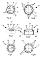
- FIG. 1 to 6 The designated in its entirety with 10, shown in Figures 1 to 6 from exemplary embodiment of a child-resistant closure designed in the manner according to the invention is shown in Figures 1, 3 and 4 shown screwed on the screw thread 12 neck 14 of a medication bottle 16.
- the closure 10 is thus a screw closure in the case shown, but this is not essential to the invention, since it or the like as a bayonet closure. could be trained. It is only essential that it is a fastener which can be fastened to the container by turning and can be removed and removed again by turning in opposite directions.
- the closure 10 consists of two parts, namely an inner cap 18 which can be screwed onto the screw thread 12 and has a cylindrical outer circumferential surface 20 and an essentially likewise cylindrical outer closure part in the form of a ring element 22 which surrounds the circumferential surface 20 of the inner cap 18 and which increases the grip speed is provided on its outer cylindrical circumferential surface in a conventional manner with longitudinal low ribs 24.
- the inner cap 18 has at its upper end in connection with the peripheral surface 20 a radially inwardly directed annular end face 26, in the outer area directly adjoining the peripheral surface 20, at regular intervals, locking recesses 28 are provided, the locking teeth in the material remaining between them 30 form.
- the ring element 22 has an elastically deformable ring flange 32, which is attached in one piece and is directed radially inwards and obliquely backwards to the bottle, the free inner boundary edge of which is supported radially within the locking teeth 30 on the annular end face 26.
- the free passage of the ring element 22 formed within the ring flange 32 is penetrated by a cylindrical extension 34 adjoining the annular end surface 26 of the inner cap 18 with a substantially flat closed end wall 36, the extension 34 having such a height that the outer surface of its end wall 36 is aligned approximately flush with the upper boundary edge of the ring element 22.
- the locking teeth 30 and 38 have - as in the closure according to the above-mentioned older proposal - each have an essentially axially extending and a ramp-like obliquely inclined to the axial engagement surface, the arrangement being such that the axially extending engagement surfaces of the locking teeth Inner cap of the ring element in the direction of closure and the inclined engagement surfaces in the direction of closure of the transmission transmit the torque exerted on the closure for closing or opening the container.
- the relatively small axial force required to deform the annular flange 32 is sufficient to couple and hold the axially extending engagement surfaces.
- the inclined engagement surfaces of the locking teeth 30, 38 interact.
- the fit between the inner cap and the neck 14 of the medication vial 16 is chosen to be sufficiently tight, the desired securing function is achieved not only at the moment the closure is released, but during the entire unscrewing process.
- Additional low projections 40 are provided on the top of the area of the inner cap end face 26 located radially within the locking teeth 30, which cooperate with knob projections 42 on the underside of the elastically deformable ring flange 32 and then also produce a ratchet noise when the ring element rotates relative to the inner cap. if no axial pressure is exerted on the ring element.
- the locking teeth 130 of the inner cap 118 in the annular end face 126 are arranged offset radially inward, specifically in the area in which the elastically deformable ring flange 132 is supported on the end face 126.
- the locking teeth 138 assigned to the ring element 122 are accordingly provided on the underside of the ring flange 132 and project in the axial direction so far from its lower boundary edge that the facing front ends of the locking teeth 130, 138 already overlap somewhat in the undeformed normal position of the ring flange 122.
- the latching teeth 130, 132 have mutually associated engagement surfaces, of which the engagement surfaces which come into contact with one another in the direction of rotation when the ring element rotates are inclined in a ramp-like manner.
- these engagement surfaces slide onto one another and, because the ring flange 132 allows an axial displacement due to its elasticity, pass over one another, the desired ratchet noise also being generated at the same time, and without additional protrusions and knob protrusions as in the case of previously described embodiment.
- the engagement surfaces of the locking teeth 130, 138 can in turn be designed to be inclined in the axial direction or also slightly in the same sense as the engagement surfaces assigned to the opening direction, in order to ensure that these engagement surfaces are held in engagement with one another when the ring element 122 is rotated in the direction of rotation without additional axial pressure being exerted.
Landscapes
- Engineering & Computer Science (AREA)
- Mechanical Engineering (AREA)
- Closures For Containers (AREA)
Applications Claiming Priority (2)
| Application Number | Priority Date | Filing Date | Title |
|---|---|---|---|
| DE3042954 | 1980-11-14 | ||
| DE19803042954 DE3042954C2 (de) | 1980-11-14 | 1980-11-14 | Kindersicherer Behälter-Verschluß |
Publications (2)
| Publication Number | Publication Date |
|---|---|
| EP0052260A1 true EP0052260A1 (fr) | 1982-05-26 |
| EP0052260B1 EP0052260B1 (fr) | 1985-01-23 |
Family
ID=6116759
Family Applications (1)
| Application Number | Title | Priority Date | Filing Date |
|---|---|---|---|
| EP19810108868 Expired EP0052260B1 (fr) | 1980-11-14 | 1981-10-24 | Bouchon de sécurité |
Country Status (2)
| Country | Link |
|---|---|
| EP (1) | EP0052260B1 (fr) |
| DE (1) | DE3042954C2 (fr) |
Cited By (3)
| Publication number | Priority date | Publication date | Assignee | Title |
|---|---|---|---|---|
| WO1993004941A1 (fr) * | 1991-09-06 | 1993-03-18 | H. Lundbeck A/S | Fermeture de securite pour recipient |
| EP0620163A1 (fr) * | 1993-04-01 | 1994-10-19 | Globol GmbH | Fermeture pour un dispositif d'évaporation |
| EP1863724A4 (fr) * | 2005-03-15 | 2013-03-27 | Hee Kwon Rho | Bouchon de securite pour enfant |
Families Citing this family (1)
| Publication number | Priority date | Publication date | Assignee | Title |
|---|---|---|---|---|
| DE3331485C2 (de) * | 1983-09-01 | 1986-08-14 | Owens-Illinois, Inc., Toledo, Ohio | Kindersicherer Verschluß |
Citations (7)
| Publication number | Priority date | Publication date | Assignee | Title |
|---|---|---|---|---|
| US3260393A (en) * | 1965-05-10 | 1966-07-12 | Roberts Simon | Safety cap for containers |
| US3394829A (en) * | 1967-04-10 | 1968-07-30 | Harris M. Peterson | Safety cap |
| DE2115741B1 (de) * | 1971-03-31 | 1972-06-29 | Grau, Hermann, 7071 Lindach | Sicherheitsverschluß |
| DE2303020A1 (de) * | 1972-02-04 | 1973-08-09 | Kerr Glass Mfg Corp | Behaelter-verschluss |
| US3853236A (en) * | 1973-12-06 | 1974-12-10 | Federal Tool & Plastics | Safety closure unit |
| GB1402006A (en) * | 1972-10-04 | 1975-08-06 | Metal Box Co Ltd | Closures for bottles and like containers |
| DE2927339A1 (de) * | 1979-07-06 | 1981-01-29 | Sanner Kg Friedr | Kindersicherer behaelter-verschluss |
Family Cites Families (3)
| Publication number | Priority date | Publication date | Assignee | Title |
|---|---|---|---|---|
| US27156A (en) * | 1860-02-14 | Island | ||
| CH519423A (de) * | 1970-02-13 | 1972-02-29 | Ciba Geigy Ag | Behälterverschluss |
| US3782604A (en) * | 1972-01-20 | 1974-01-01 | M Kessler | Screw cap with safety cover |
-
1980
- 1980-11-14 DE DE19803042954 patent/DE3042954C2/de not_active Expired
-
1981
- 1981-10-24 EP EP19810108868 patent/EP0052260B1/fr not_active Expired
Patent Citations (7)
| Publication number | Priority date | Publication date | Assignee | Title |
|---|---|---|---|---|
| US3260393A (en) * | 1965-05-10 | 1966-07-12 | Roberts Simon | Safety cap for containers |
| US3394829A (en) * | 1967-04-10 | 1968-07-30 | Harris M. Peterson | Safety cap |
| DE2115741B1 (de) * | 1971-03-31 | 1972-06-29 | Grau, Hermann, 7071 Lindach | Sicherheitsverschluß |
| DE2303020A1 (de) * | 1972-02-04 | 1973-08-09 | Kerr Glass Mfg Corp | Behaelter-verschluss |
| GB1402006A (en) * | 1972-10-04 | 1975-08-06 | Metal Box Co Ltd | Closures for bottles and like containers |
| US3853236A (en) * | 1973-12-06 | 1974-12-10 | Federal Tool & Plastics | Safety closure unit |
| DE2927339A1 (de) * | 1979-07-06 | 1981-01-29 | Sanner Kg Friedr | Kindersicherer behaelter-verschluss |
Cited By (3)
| Publication number | Priority date | Publication date | Assignee | Title |
|---|---|---|---|---|
| WO1993004941A1 (fr) * | 1991-09-06 | 1993-03-18 | H. Lundbeck A/S | Fermeture de securite pour recipient |
| EP0620163A1 (fr) * | 1993-04-01 | 1994-10-19 | Globol GmbH | Fermeture pour un dispositif d'évaporation |
| EP1863724A4 (fr) * | 2005-03-15 | 2013-03-27 | Hee Kwon Rho | Bouchon de securite pour enfant |
Also Published As
| Publication number | Publication date |
|---|---|
| DE3042954A1 (de) | 1982-07-22 |
| EP0052260B1 (fr) | 1985-01-23 |
| DE3042954C2 (de) | 1986-09-04 |
Similar Documents
| Publication | Publication Date | Title |
|---|---|---|
| DE69833621T2 (de) | Kindersicherer Schraubverschluss | |
| DE69714801T2 (de) | Behälter- und Verschlusseinheit mit Kindersicherung | |
| DE4314923C2 (de) | Verschlußkappe zum Verschließen einer Flasche | |
| DE3784618T2 (de) | Behaelterverschluss. | |
| DE2828100C2 (de) | Kindersicherer Verschluß | |
| DE2532193C2 (de) | Sicherheits-Schraubverschluß für Behälter | |
| DE3336908A1 (de) | Originalitaetsverschluss aus kunststoff | |
| EP0257481B1 (fr) | Fermeture filetée résistante aux enfants | |
| DE2321758A1 (de) | Sicherheitsverschluss fuer einen behaelter mit einer verschlusskappe | |
| DE2828063A1 (de) | Kindersicherer sicherheitsverschluss | |
| DE2208482A1 (de) | Kindersicherer verschluss mit einem sperrgetriebe | |
| EP0123810A1 (fr) | Fermeture de sécurité | |
| DE2249009A1 (de) | Sicherheitsverschluss | |
| EP0052260B1 (fr) | Bouchon de sécurité | |
| DE2307205A1 (de) | Sicherheits-flaschenverschluss | |
| EP0297160A1 (fr) | Capuchon à vis de sécurité | |
| DE2533230C2 (de) | Schraubkappenverschluß mit Kinderschutzsicherung für Flaschen und ähnliche Behälter | |
| DE7534301U (de) | Kindersicherer Verschluss fuer Behaelter insbesondere fuer rieselfaehige Gueter enthaltende Behaelter | |
| DE3207049C2 (fr) | ||
| DE2927339A1 (de) | Kindersicherer behaelter-verschluss | |
| EP0060983B1 (fr) | Récipient avec fermeture de sécurité | |
| DE4002967A1 (de) | Schraubverschluss fuer originalitaetssicherung fuer insbesondere weithalsbehaelter | |
| DE2121739A1 (de) | Sicherheits-Kappenverschluß für Gefäße mit Hals | |
| WO1989010313A1 (fr) | Procede de montage de couvercles en plastique | |
| CH570312A5 (en) | Medicine bottle safety cap - has inner and outer portions with conical friction faces thrust together axially |
Legal Events
| Date | Code | Title | Description |
|---|---|---|---|
| PUAI | Public reference made under article 153(3) epc to a published international application that has entered the european phase |
Free format text: ORIGINAL CODE: 0009012 |
|
| AK | Designated contracting states |
Designated state(s): BE CH GB LU NL |
|
| 17P | Request for examination filed |
Effective date: 19820819 |
|
| GRAA | (expected) grant |
Free format text: ORIGINAL CODE: 0009210 |
|
| AK | Designated contracting states |
Designated state(s): BE CH GB LI LU NL |
|
| PG25 | Lapsed in a contracting state [announced via postgrant information from national office to epo] |
Ref country code: LU Free format text: LAPSE BECAUSE OF NON-PAYMENT OF DUE FEES Effective date: 19851031 |
|
| PLBE | No opposition filed within time limit |
Free format text: ORIGINAL CODE: 0009261 |
|
| STAA | Information on the status of an ep patent application or granted ep patent |
Free format text: STATUS: NO OPPOSITION FILED WITHIN TIME LIMIT |
|
| 26N | No opposition filed | ||
| PGFP | Annual fee paid to national office [announced via postgrant information from national office to epo] |
Ref country code: NL Payment date: 19871031 Year of fee payment: 7 |
|
| PG25 | Lapsed in a contracting state [announced via postgrant information from national office to epo] |
Ref country code: GB Effective date: 19891024 |
|
| PG25 | Lapsed in a contracting state [announced via postgrant information from national office to epo] |
Ref country code: LI Effective date: 19891031 Ref country code: CH Effective date: 19891031 Ref country code: BE Effective date: 19891031 |
|
| BERE | Be: lapsed |
Owner name: FRIEDRICH SANNER G.M.B.H: & CO. K.G. SPRITZGUSSWE Effective date: 19891031 |
|
| PG25 | Lapsed in a contracting state [announced via postgrant information from national office to epo] |
Ref country code: NL Effective date: 19900501 |
|
| NLV4 | Nl: lapsed or anulled due to non-payment of the annual fee | ||
| GBPC | Gb: european patent ceased through non-payment of renewal fee | ||
| REG | Reference to a national code |
Ref country code: CH Ref legal event code: PL |