EP0052318B1 - Kraftaufnehmer - Google Patents
Kraftaufnehmer Download PDFInfo
- Publication number
- EP0052318B1 EP0052318B1 EP81109557A EP81109557A EP0052318B1 EP 0052318 B1 EP0052318 B1 EP 0052318B1 EP 81109557 A EP81109557 A EP 81109557A EP 81109557 A EP81109557 A EP 81109557A EP 0052318 B1 EP0052318 B1 EP 0052318B1
- Authority
- EP
- European Patent Office
- Prior art keywords
- tines
- force
- resonator
- transmitting member
- support means
- Prior art date
- Legal status (The legal status is an assumption and is not a legal conclusion. Google has not performed a legal analysis and makes no representation as to the accuracy of the status listed.)
- Expired
Links
- 230000008878 coupling Effects 0.000 claims description 6
- 238000010168 coupling process Methods 0.000 claims description 6
- 238000005859 coupling reaction Methods 0.000 claims description 6
- 230000000694 effects Effects 0.000 description 4
- 239000012530 fluid Substances 0.000 description 2
- 238000009434 installation Methods 0.000 description 2
- 239000010453 quartz Substances 0.000 description 2
- 230000035945 sensitivity Effects 0.000 description 2
- VYPSYNLAJGMNEJ-UHFFFAOYSA-N silicon dioxide Inorganic materials O=[Si]=O VYPSYNLAJGMNEJ-UHFFFAOYSA-N 0.000 description 2
- 239000000725 suspension Substances 0.000 description 2
- 239000013078 crystal Substances 0.000 description 1
- 230000007613 environmental effect Effects 0.000 description 1
- 238000012886 linear function Methods 0.000 description 1
- 238000004519 manufacturing process Methods 0.000 description 1
- 238000000034 method Methods 0.000 description 1
- 239000000203 mixture Substances 0.000 description 1
- 230000010355 oscillation Effects 0.000 description 1
- 230000021715 photosynthesis, light harvesting Effects 0.000 description 1
- 238000000926 separation method Methods 0.000 description 1
- 230000002459 sustained effect Effects 0.000 description 1
Images
Classifications
-
- G—PHYSICS
- G01—MEASURING; TESTING
- G01L—MEASURING FORCE, STRESS, TORQUE, WORK, MECHANICAL POWER, MECHANICAL EFFICIENCY, OR FLUID PRESSURE
- G01L1/00—Measuring force or stress, in general
- G01L1/16—Measuring force or stress, in general using properties of piezoelectric devices
- G01L1/162—Measuring force or stress, in general using properties of piezoelectric devices using piezoelectric resonators
-
- Y—GENERAL TAGGING OF NEW TECHNOLOGICAL DEVELOPMENTS; GENERAL TAGGING OF CROSS-SECTIONAL TECHNOLOGIES SPANNING OVER SEVERAL SECTIONS OF THE IPC; TECHNICAL SUBJECTS COVERED BY FORMER USPC CROSS-REFERENCE ART COLLECTIONS [XRACs] AND DIGESTS
- Y10—TECHNICAL SUBJECTS COVERED BY FORMER USPC
- Y10S—TECHNICAL SUBJECTS COVERED BY FORMER USPC CROSS-REFERENCE ART COLLECTIONS [XRACs] AND DIGESTS
- Y10S73/00—Measuring and testing
- Y10S73/01—Vibration
Definitions
- the present invention relates to a force transducer, comprising a double-ended tuning fork resonator having a pair of elongated parallel tines extending between spaced-apart nodes.
- a force transducer is known from FR-A-2 013 631.
- the force transmitting column is not supported about a pivot axis and the tines of the tuning fork resonator occupy the same plane as the force transmitting column. Therefore, it is doubtful that the known installation is capable of applying loads from the pan equally to each of the tines of the resonator.
- the parallel beams would pivot downwardly. This downward pivotal movement of the beams would cause the force transmitting column to also move to the left. Friction between the lower end of the column and the resonator would, undoubtedly, exert a leftward movement at the upper end of the tuning fork resonator. This leftward movement or force would cause the left side tine to receive a greater compressional load than the right side tine.
- a tuning fork cut from a quartz plate in which the tuning fork resonator, the mounting pads and the coupling member are integrally formed from the quartz crystal.
- the tuning fork is used within a fluid pressure measuring means. Because of the special kind of mounting and the balance inherent to the use of forces provided by fluid pressure, there is no apparent risk of the tines of the tuning fork being unequally loaded. However, applying forces by mechanical means would, inevitably, disturb the balance of the system.
- a force transmitting member is provided mounted on a base through support means which are relatively compliant about a pivot axis while relatively rigid in the transverse directions, said resonator having one of its nodes connected to said force transmitting member with the plane of the tines of said resonator parallel to said pivot axis such that pivotal movement of said force transmitting member loads substantially equally said tines while the rigidity of said support means in the transverse directions restricts non-symmetrical loading of said resonator.
- this special kind of mounting of the fork resonator prohibits any imbalance in the loading of the tines of the resonator.
- the resonant frequency in Hertz, f o of an unstressed, fixed-ended, flexurally vibrating beam of length L, thickness t, width b, modulus of elasticity E, and density d is given by the formula:
- the resonant frequency is generally a non-linear function of the applied load F
- the first-order load sensitivity S may be calculated as: The quantitative relationships between resonant frequency, applied load, and resonator dimensions and compositions can be determined from the above formulas.
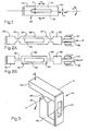
- Fig. 1 is a plan view showing a conventional closed-end tuning fork 20 as described in the aforementioned patent to Erdley.
- This device 20 achieves low energy loss characteristic of high "Q" operation by driving a pair of closely matched tines 22 180 degrees out of phase, thus cancelling the reactive moments and forces which might be transmitted to mounting nodes 24 from which the tines 22 project. Even if the tines 22 of a force sensor are precisely matched dimensionally in the unstressed state, they will not have the same resonant frequency if no provisions have been made for equal loading. Unequal tine stress can result from dimensional differences, eccentric loads, and applied moments.
- Discontinuities in the force-versus-frequency output can occur if the electronic oscillator circuitry can lock in on more than one well-defined resonant peak. Furthermore, poor cancellation of end effects occurs with mismatched tines, resulting in energy dissipation through the mounting nodes 24, thereby lowering the resonator "Q". Energy losses may be so great as to reduce the oscillator circuitry gain to less than one, resulting in a failure to maintain oscillations of the tines 22. Thus it is most important to substantially equalize the loads applied to the tines 22 so that a single, well-defined, high "Q" resonant peak occurs over the full loading range.
- Figs. 2A and 2B illustrate one embodiment of the inventive load-equalizing structure, which includes centering flexures 30 (Fig. 2A) and compliant bars 32 (Fig. 2B) extending between nodes 34 and respective mounting pad 36 which allow equal loading of tines 38.
- the flexures 30 are compliant about an axis perpendicular to the plane of tine vibration; however, the flexures 30 are relatively stiff in the cross-axis and longitudinal axis directions.
- the flexures 30 serve to reduce the effects of moments applied about an axis perpendicular to the plane of tine vibration by rotation of the mounting pads 36, caused either by initially mounting the pads 36 out of alignment or by rotational moments imparted by a force-transmitting member, such as a bar 39 fastened to one mounting pad 36 and slidably received by a fixed support frame 40.
- the force-transmitting member must be constrained to move in substantially a single direction since the flexure 30 is incapable of resisting moments applied to the mounting pads 36 without also applying those moments to the tines 38.
- the force-transmitting member applies a force to the mounting pads 36 at the center of the pads 36 and in a longitudinal direction parallel to the tines 38.
- the force-transmitting member may apply a force to the mounting pads 36 which is either off-center or not parallel to the tines 38. Either of these conditions causes the mounting pads to rotate and, if the flexure is not compliant, will non-symmetrically load the tines 38.
- the flexures being highly compliant, reduce non-symmetrical tine loading, as expressed in Equation 3.
- the flexures 30 can be centered equally between the tines 38 to reduce the eccentric loading effects of Equation 3. This centering is readily accomplished by manufacturing the closed-end tuning fork configuration using conventional photolithographic techniques.
- the compliant bars 32 of Fig. 2B absorb rotational movements of the mounting pads 36 in the same manner as the flexures 30. However, they are also capable of absorbing transverse movement of the mounting pads without applying significant non-symmetrical loads to the tines 38.
- One force-transmitting member constrained to move in a single direction is the bar 39 slidably mounted in the frame 40 of Fig. 2.
- Another force-transmitting structure which can be used with either a conventional double tuning fork or the flexure or compliant bar tuning fork of Fig. 2 is illustrated in Fig. 3.
- the structure of Fig. 3 allows equal forces to be applied to both tines 42 of a closed-end tuning fork resonator 44.
- a flexure hinge 46 connected between a base member 48 and a force-transmitting bar 50 operates as a compliant pivot about axis A-A while remaining quite stiff in the cross-axis direction.
- the hinge axis A-A is perpendicular to the longitudinal axis of the closed-end tuning fork resonator 44 such that the plane of vibration of the tines 42 is parallel to the compliant axis A-A.
- forces F and moments M which produce a torque about axis A-A are applied to the closed-end tuning fork resonator 44; and since both tines 42 and equidistant from axis A-A, they are substantially equally loaded.
- Substantially equal loading of the tines 42 occurs when the coupling between tines 42 is sufficient to maintain a single, well-defined, high "Q" resonant peak over the full loading range.
- the critera for substantially equal loading would require a sufficiently large ratio of distance between pivot 46 and resonator 44 to separation between tines 42.
- Cross-axis forces and moments are sustained by the suspension system and not transmitted to the tines 42.
- the suspension system need not be a flexure hinge pivot but any device which is compliant about only one axis. To the extent that any cross-axis forces and moments are transmitted to the resonator 44, they can be isolated from the tines 42 by using the resonators of Figs. 2A and 2B in place of the conventional resonator 44 as shown.
Landscapes
- Physics & Mathematics (AREA)
- General Physics & Mathematics (AREA)
- Piezo-Electric Or Mechanical Vibrators, Or Delay Or Filter Circuits (AREA)
Claims (5)
Applications Claiming Priority (2)
| Application Number | Priority Date | Filing Date | Title |
|---|---|---|---|
| US207694 | 1980-11-17 | ||
| US06/207,694 US4384495A (en) | 1980-11-17 | 1980-11-17 | Mounting system for applying forces to load-sensitive resonators |
Publications (2)
| Publication Number | Publication Date |
|---|---|
| EP0052318A1 EP0052318A1 (de) | 1982-05-26 |
| EP0052318B1 true EP0052318B1 (de) | 1986-05-14 |
Family
ID=22771615
Family Applications (1)
| Application Number | Title | Priority Date | Filing Date |
|---|---|---|---|
| EP81109557A Expired EP0052318B1 (de) | 1980-11-17 | 1981-11-06 | Kraftaufnehmer |
Country Status (6)
| Country | Link |
|---|---|
| US (1) | US4384495A (de) |
| EP (1) | EP0052318B1 (de) |
| JP (1) | JPS57113335A (de) |
| CA (1) | CA1165584A (de) |
| DE (1) | DE3174643D1 (de) |
| MX (1) | MX154128A (de) |
Families Citing this family (33)
| Publication number | Priority date | Publication date | Assignee | Title |
|---|---|---|---|---|
| US4526247A (en) * | 1983-01-18 | 1985-07-02 | Ohaus Scale Corporation | Weighing scale transducer |
| EP0144311B1 (de) * | 1983-04-01 | 1992-07-15 | Quartex, Inc. | Doppelstabresonator-kraftwandler mit beschränkter longitudinal-pumpwirkung |
| JPS6010122A (ja) * | 1983-06-30 | 1985-01-19 | Shinko Denshi Kk | 荷重変換機構 |
| GB8418914D0 (en) * | 1984-07-25 | 1984-08-30 | Standard Telephones Cables Ltd | Transducer |
| DE3505165C2 (de) * | 1985-02-15 | 1986-12-04 | Danfoss A/S, Nordborg | Verfahren und Vorrichtung zum Messen einer Kraft |
| US4706259A (en) * | 1985-12-30 | 1987-11-10 | Sundstrand Data Control, Inc. | Mounting and isolation system for tuning fork temperature sensor |
| DE3776911D1 (de) * | 1986-07-01 | 1992-04-02 | Sensor Int | Vibrationskraftsensor. |
| US4970903A (en) * | 1987-10-22 | 1990-11-20 | Hanson Richard A | Force sensing device |
| WO1993010428A1 (en) * | 1991-11-12 | 1993-05-27 | Masstech Scientific Pty. Ltd. | Force or load sensors |
| FR2685960B1 (fr) * | 1992-01-08 | 1994-03-25 | Stanislas Konieczka | Element de capteur de force en double diapason. |
| US5391844A (en) * | 1992-04-03 | 1995-02-21 | Weigh-Tronix Inc | Load cell |
| US5313023A (en) * | 1992-04-03 | 1994-05-17 | Weigh-Tronix, Inc. | Load cell |
| US5442146A (en) * | 1992-04-03 | 1995-08-15 | Weigh-Tronix, Inc. | Counting scale and load cell assembly therefor |
| US5336854A (en) * | 1992-04-03 | 1994-08-09 | Weigh-Tronix, Inc. | Electronic force sensing load cell |
| US5604336A (en) * | 1995-03-08 | 1997-02-18 | Weigh-Tronix, Inc. | Load cell with composite end beams having portions with different elastic modulus |
| US5604472A (en) * | 1995-12-01 | 1997-02-18 | Illinois Superconductor Corporation | Resonator mounting mechanism |
| US5739431A (en) * | 1996-06-13 | 1998-04-14 | Alliedsignal, Inc. | Miniature magnetometer-accelerometer |
| US5889448A (en) * | 1997-06-05 | 1999-03-30 | Illinois Superconductor Corporation | Resonator mounting mechanism |
| US6497152B2 (en) | 2001-02-23 | 2002-12-24 | Paroscientific, Inc. | Method for eliminating output discontinuities in digital pressure transducers and digital pressure transducer employing same |
| US6633008B2 (en) | 2001-02-27 | 2003-10-14 | Weigh-Tronix, Inc. | Electronic force sensing shock resistant load cell |
| JP2002365123A (ja) * | 2001-06-11 | 2002-12-18 | Yamato Scale Co Ltd | 水晶振動子を用いた荷重センサ |
| JP4848973B2 (ja) * | 2007-02-15 | 2011-12-28 | セイコーエプソン株式会社 | 加速度検知ユニット及び加速度センサ |
| CN100453830C (zh) * | 2007-03-30 | 2009-01-21 | 北京航空航天大学 | 双曲杆型空心柔性铰链 |
| JP2010019826A (ja) * | 2008-03-25 | 2010-01-28 | Epson Toyocom Corp | 圧力センサ |
| JP2009258085A (ja) * | 2008-03-25 | 2009-11-05 | Epson Toyocom Corp | 圧力センサおよびその製造方法 |
| JP2010019827A (ja) * | 2008-06-11 | 2010-01-28 | Epson Toyocom Corp | 圧力センサー |
| JP2010019828A (ja) * | 2008-06-11 | 2010-01-28 | Epson Toyocom Corp | 圧力センサー用ダイアフラムおよび圧力センサー |
| JP2010019829A (ja) * | 2008-06-11 | 2010-01-28 | Epson Toyocom Corp | 圧力センサー |
| JP5187529B2 (ja) * | 2008-07-22 | 2013-04-24 | セイコーエプソン株式会社 | 圧力センサー |
| EP2356743A1 (de) | 2008-11-07 | 2011-08-17 | Greenray Industries, Inc. | Kristalloszillator mit verringerter beschleunigungsempfindlichkeit |
| JP4756394B2 (ja) * | 2009-03-04 | 2011-08-24 | セイコーエプソン株式会社 | 圧力センサー |
| JP2012073163A (ja) | 2010-09-29 | 2012-04-12 | Seiko Epson Corp | 圧力センサー |
| RU2541375C1 (ru) * | 2013-08-27 | 2015-02-10 | Российская Федерация, от имени которой выступает Государственная корпорация по атомной энергии "Росатом" | Резонатор силочувствительный |
Family Cites Families (9)
| Publication number | Priority date | Publication date | Assignee | Title |
|---|---|---|---|---|
| US3479536A (en) * | 1967-03-14 | 1969-11-18 | Singer General Precision | Piezoelectric force transducer |
| US3470400A (en) * | 1967-12-21 | 1969-09-30 | Singer General Precision | Single beam force transducer with integral mounting isolation |
| CH497691A (de) * | 1968-07-24 | 1970-10-15 | Sauter Kg August | Elektromechanischer Kraft-Frequenzwandler für Waagen |
| US3672220A (en) * | 1970-02-12 | 1972-06-27 | Solartron Electronic Group | Force-transducers |
| DE2203204C3 (de) * | 1972-01-24 | 1980-03-06 | August Sauter Gmbh, 7470 Albstadt | Kraftmesser mit Drehschwinger |
| JPS5856425B2 (ja) * | 1978-10-11 | 1983-12-14 | 横河電機株式会社 | 力変換機構 |
| US4215570A (en) * | 1979-04-20 | 1980-08-05 | The United States Of America As Represented By The United States Department Of Energy | Miniature quartz resonator force transducer |
| JPS596369B2 (ja) * | 1979-05-11 | 1984-02-10 | 横河電機株式会社 | 力変換機構 |
| GB2049188B (en) * | 1979-05-14 | 1984-02-01 | Rosemount Inc | Vibrating beam pressure sensor |
-
1980
- 1980-11-17 US US06/207,694 patent/US4384495A/en not_active Expired - Lifetime
-
1981
- 1981-11-06 EP EP81109557A patent/EP0052318B1/de not_active Expired
- 1981-11-06 DE DE8181109557T patent/DE3174643D1/de not_active Expired
- 1981-11-12 CA CA000389900A patent/CA1165584A/en not_active Expired
- 1981-11-13 MX MX190095A patent/MX154128A/es unknown
- 1981-11-17 JP JP56184350A patent/JPS57113335A/ja active Pending
Also Published As
| Publication number | Publication date |
|---|---|
| EP0052318A1 (de) | 1982-05-26 |
| MX154128A (es) | 1987-05-22 |
| US4384495A (en) | 1983-05-24 |
| JPS57113335A (en) | 1982-07-14 |
| CA1165584A (en) | 1984-04-17 |
| DE3174643D1 (en) | 1986-06-19 |
Similar Documents
| Publication | Publication Date | Title |
|---|---|---|
| EP0052318B1 (de) | Kraftaufnehmer | |
| US4881408A (en) | Low profile accelerometer | |
| US4656383A (en) | Vibrating beam force transducer with single isolator spring | |
| EP0441910B1 (de) | Monolithischer beschleunigungsmesser mit biegsam montiertem kraftwandler | |
| EP0270664B1 (de) | Temperaturkompensation bei einem beschleunigungsmesser | |
| US5313023A (en) | Load cell | |
| US4766768A (en) | Accelerometer with isolator for common mode inputs | |
| US5165279A (en) | Monolithic accelerometer with flexurally mounted force transducer | |
| US4517841A (en) | Accelerometer with beam resonator force transducer | |
| US5005413A (en) | Accelerometer with coplanar push-pull force transducers | |
| US4299122A (en) | Force transducer | |
| US4838369A (en) | Load cell having digital output | |
| CA1206170A (en) | Weighing scale transducer | |
| US4804875A (en) | Monolythic resonator vibrating beam accelerometer | |
| EP0411117A1 (de) | Einheitlicher zieh-druck-kraftumwandler | |
| US5186053A (en) | Temperature compensated proofmass assembly for accelerometers | |
| EP0271574A4 (en) | Accelerometer with floating beam temperature compensation | |
| US5036715A (en) | Cantilevered force sensing assembly utilizing one or two resonating force sensing devices | |
| US5289719A (en) | Accelerometer with temperature compensation and matched force transducers | |
| US4706259A (en) | Mounting and isolation system for tuning fork temperature sensor | |
| GB2123953A (en) | Elastic surface wave accelerometers | |
| CA2064923A1 (en) | Oscillator supporting structure for an oscillating type accelerometer |
Legal Events
| Date | Code | Title | Description |
|---|---|---|---|
| PUAI | Public reference made under article 153(3) epc to a published international application that has entered the european phase |
Free format text: ORIGINAL CODE: 0009012 |
|
| AK | Designated contracting states |
Designated state(s): BE CH DE FR GB IT NL |
|
| 17P | Request for examination filed |
Effective date: 19821029 |
|
| GRAA | (expected) grant |
Free format text: ORIGINAL CODE: 0009210 |
|
| AK | Designated contracting states |
Kind code of ref document: B1 Designated state(s): BE CH DE FR GB IT LI NL |
|
| PG25 | Lapsed in a contracting state [announced via postgrant information from national office to epo] |
Ref country code: NL Effective date: 19860514 Ref country code: IT Free format text: LAPSE BECAUSE OF FAILURE TO SUBMIT A TRANSLATION OF THE DESCRIPTION OR TO PAY THE FEE WITHIN THE PRESCRIBED TIME-LIMIT;WARNING: LAPSES OF ITALIAN PATENTS WITH EFFECTIVE DATE BEFORE 2007 MAY HAVE OCCURRED AT ANY TIME BEFORE 2007. THE CORRECT EFFECTIVE DATE MAY BE DIFFERENT FROM THE ONE RECORDED. Effective date: 19860514 Ref country code: BE Effective date: 19860514 |
|
| REF | Corresponds to: |
Ref document number: 3174643 Country of ref document: DE Date of ref document: 19860619 |
|
| ET | Fr: translation filed | ||
| NLV1 | Nl: lapsed or annulled due to failure to fulfill the requirements of art. 29p and 29m of the patents act | ||
| PLBE | No opposition filed within time limit |
Free format text: ORIGINAL CODE: 0009261 |
|
| STAA | Information on the status of an ep patent application or granted ep patent |
Free format text: STATUS: NO OPPOSITION FILED WITHIN TIME LIMIT |
|
| 26N | No opposition filed | ||
| PGFP | Annual fee paid to national office [announced via postgrant information from national office to epo] |
Ref country code: FR Payment date: 19971112 Year of fee payment: 17 |
|
| PGFP | Annual fee paid to national office [announced via postgrant information from national office to epo] |
Ref country code: DE Payment date: 19971114 Year of fee payment: 17 |
|
| PGFP | Annual fee paid to national office [announced via postgrant information from national office to epo] |
Ref country code: CH Payment date: 19971126 Year of fee payment: 17 |
|
| PG25 | Lapsed in a contracting state [announced via postgrant information from national office to epo] |
Ref country code: LI Free format text: LAPSE BECAUSE OF NON-PAYMENT OF DUE FEES Effective date: 19981130 Ref country code: CH Free format text: LAPSE BECAUSE OF NON-PAYMENT OF DUE FEES Effective date: 19981130 |
|
| REG | Reference to a national code |
Ref country code: CH Ref legal event code: PL |
|
| PG25 | Lapsed in a contracting state [announced via postgrant information from national office to epo] |
Ref country code: FR Free format text: LAPSE BECAUSE OF NON-PAYMENT OF DUE FEES Effective date: 19990730 |
|
| REG | Reference to a national code |
Ref country code: FR Ref legal event code: ST |
|
| PG25 | Lapsed in a contracting state [announced via postgrant information from national office to epo] |
Ref country code: DE Free format text: LAPSE BECAUSE OF NON-PAYMENT OF DUE FEES Effective date: 19990901 |
|
| PGFP | Annual fee paid to national office [announced via postgrant information from national office to epo] |
Ref country code: GB Payment date: 20001121 Year of fee payment: 20 |
|
| PG25 | Lapsed in a contracting state [announced via postgrant information from national office to epo] |
Ref country code: GB Free format text: LAPSE BECAUSE OF EXPIRATION OF PROTECTION Effective date: 20011105 |
|
| REG | Reference to a national code |
Ref country code: GB Ref legal event code: PE20 Effective date: 20011105 |