EP0052320B1 - Volet à rouleau - Google Patents
Volet à rouleau Download PDFInfo
- Publication number
- EP0052320B1 EP0052320B1 EP81109569A EP81109569A EP0052320B1 EP 0052320 B1 EP0052320 B1 EP 0052320B1 EP 81109569 A EP81109569 A EP 81109569A EP 81109569 A EP81109569 A EP 81109569A EP 0052320 B1 EP0052320 B1 EP 0052320B1
- Authority
- EP
- European Patent Office
- Prior art keywords
- slats
- guide flange
- roller shutter
- guide
- journals
- Prior art date
- Legal status (The legal status is an assumption and is not a legal conclusion. Google has not performed a legal analysis and makes no representation as to the accuracy of the status listed.)
- Expired
Links
- 230000008878 coupling Effects 0.000 claims description 58
- 238000010168 coupling process Methods 0.000 claims description 58
- 238000005859 coupling reaction Methods 0.000 claims description 58
- 241000446313 Lamella Species 0.000 description 8
- 230000000694 effects Effects 0.000 description 2
- 238000000034 method Methods 0.000 description 2
- 238000011161 development Methods 0.000 description 1
- 230000018109 developmental process Effects 0.000 description 1
- 239000002184 metal Substances 0.000 description 1
- 239000004753 textile Substances 0.000 description 1
Images


Classifications
-
- E—FIXED CONSTRUCTIONS
- E06—DOORS, WINDOWS, SHUTTERS, OR ROLLER BLINDS IN GENERAL; LADDERS
- E06B—FIXED OR MOVABLE CLOSURES FOR OPENINGS IN BUILDINGS, VEHICLES, FENCES OR LIKE ENCLOSURES IN GENERAL, e.g. DOORS, WINDOWS, BLINDS, GATES
- E06B9/00—Screening or protective devices for wall or similar openings, with or without operating or securing mechanisms; Closures of similar construction
- E06B9/56—Operating, guiding or securing devices or arrangements for roll-type closures; Spring drums; Tape drums; Counterweighting arrangements therefor
- E06B9/58—Guiding devices
-
- E—FIXED CONSTRUCTIONS
- E06—DOORS, WINDOWS, SHUTTERS, OR ROLLER BLINDS IN GENERAL; LADDERS
- E06B—FIXED OR MOVABLE CLOSURES FOR OPENINGS IN BUILDINGS, VEHICLES, FENCES OR LIKE ENCLOSURES IN GENERAL, e.g. DOORS, WINDOWS, BLINDS, GATES
- E06B9/00—Screening or protective devices for wall or similar openings, with or without operating or securing mechanisms; Closures of similar construction
- E06B9/24—Screens or other constructions affording protection against light, especially against sunshine; Similar screens for privacy or appearance; Slat blinds
- E06B9/26—Lamellar or like blinds, e.g. venetian blinds
- E06B9/28—Lamellar or like blinds, e.g. venetian blinds with horizontal lamellae, e.g. non-liftable
- E06B9/30—Lamellar or like blinds, e.g. venetian blinds with horizontal lamellae, e.g. non-liftable liftable
- E06B9/32—Operating, guiding, or securing devices therefor
-
- E—FIXED CONSTRUCTIONS
- E06—DOORS, WINDOWS, SHUTTERS, OR ROLLER BLINDS IN GENERAL; LADDERS
- E06B—FIXED OR MOVABLE CLOSURES FOR OPENINGS IN BUILDINGS, VEHICLES, FENCES OR LIKE ENCLOSURES IN GENERAL, e.g. DOORS, WINDOWS, BLINDS, GATES
- E06B9/00—Screening or protective devices for wall or similar openings, with or without operating or securing mechanisms; Closures of similar construction
- E06B9/24—Screens or other constructions affording protection against light, especially against sunshine; Similar screens for privacy or appearance; Slat blinds
- E06B9/26—Lamellar or like blinds, e.g. venetian blinds
- E06B9/28—Lamellar or like blinds, e.g. venetian blinds with horizontal lamellae, e.g. non-liftable
- E06B9/34—Lamellar or like blinds, e.g. venetian blinds with horizontal lamellae, e.g. non-liftable roller-type; Roller shutters with adjustable lamellae
-
- E—FIXED CONSTRUCTIONS
- E06—DOORS, WINDOWS, SHUTTERS, OR ROLLER BLINDS IN GENERAL; LADDERS
- E06B—FIXED OR MOVABLE CLOSURES FOR OPENINGS IN BUILDINGS, VEHICLES, FENCES OR LIKE ENCLOSURES IN GENERAL, e.g. DOORS, WINDOWS, BLINDS, GATES
- E06B9/00—Screening or protective devices for wall or similar openings, with or without operating or securing mechanisms; Closures of similar construction
- E06B9/56—Operating, guiding or securing devices or arrangements for roll-type closures; Spring drums; Tape drums; Counterweighting arrangements therefor
- E06B9/80—Safety measures against dropping or unauthorised opening; Braking or immobilising devices; Devices for limiting unrolling
- E06B9/82—Safety measures against dropping or unauthorised opening; Braking or immobilising devices; Devices for limiting unrolling automatic
- E06B9/86—Safety measures against dropping or unauthorised opening; Braking or immobilising devices; Devices for limiting unrolling automatic against unauthorised opening
-
- E—FIXED CONSTRUCTIONS
- E06—DOORS, WINDOWS, SHUTTERS, OR ROLLER BLINDS IN GENERAL; LADDERS
- E06B—FIXED OR MOVABLE CLOSURES FOR OPENINGS IN BUILDINGS, VEHICLES, FENCES OR LIKE ENCLOSURES IN GENERAL, e.g. DOORS, WINDOWS, BLINDS, GATES
- E06B9/00—Screening or protective devices for wall or similar openings, with or without operating or securing mechanisms; Closures of similar construction
- E06B9/02—Shutters, movable grilles, or other safety closing devices, e.g. against burglary
- E06B9/08—Roll-type closures
- E06B9/11—Roller shutters
- E06B9/15—Roller shutters with closing members formed of slats or the like
- E06B2009/1577—Slat end pieces used for guiding shutter
- E06B2009/1583—Slat end pieces used for guiding shutter inserted in slat cavity
-
- E—FIXED CONSTRUCTIONS
- E06—DOORS, WINDOWS, SHUTTERS, OR ROLLER BLINDS IN GENERAL; LADDERS
- E06B—FIXED OR MOVABLE CLOSURES FOR OPENINGS IN BUILDINGS, VEHICLES, FENCES OR LIKE ENCLOSURES IN GENERAL, e.g. DOORS, WINDOWS, BLINDS, GATES
- E06B9/00—Screening or protective devices for wall or similar openings, with or without operating or securing mechanisms; Closures of similar construction
- E06B9/02—Shutters, movable grilles, or other safety closing devices, e.g. against burglary
- E06B9/08—Roll-type closures
- E06B9/11—Roller shutters
- E06B9/15—Roller shutters with closing members formed of slats or the like
- E06B2009/1577—Slat end pieces used for guiding shutter
- E06B2009/1588—Slat end pieces used for guiding shutter inserted in engaging section of adjacent slats
-
- E—FIXED CONSTRUCTIONS
- E06—DOORS, WINDOWS, SHUTTERS, OR ROLLER BLINDS IN GENERAL; LADDERS
- E06B—FIXED OR MOVABLE CLOSURES FOR OPENINGS IN BUILDINGS, VEHICLES, FENCES OR LIKE ENCLOSURES IN GENERAL, e.g. DOORS, WINDOWS, BLINDS, GATES
- E06B9/00—Screening or protective devices for wall or similar openings, with or without operating or securing mechanisms; Closures of similar construction
- E06B9/56—Operating, guiding or securing devices or arrangements for roll-type closures; Spring drums; Tape drums; Counterweighting arrangements therefor
- E06B9/80—Safety measures against dropping or unauthorised opening; Braking or immobilising devices; Devices for limiting unrolling
- E06B2009/801—Locking arrangements
- E06B2009/805—Locking arrangements located on or in the guides
Definitions
- the invention relates to a roller shutter according to the preamble of claim 1.
- roller shutters are known from DE-C-1 266 475 in which the slats can be pivoted out of their vertical roller shutter position into an inclined or flared blind position.
- the curtain is moved perpendicular to the curtain plane when the wind is strong, the pins striking the guide webs and causing undesirable wind noise.
- the curtain particularly in the blind position, represents a particularly large area of attack for wind loads and therefore leads to particularly strong wind noise and movements.
- the swiveling slats can be swiveled from the roller shutter position into any inclined positions solely by wind influences and thereby open and clatter the roller shutter curtain, which is closed per se.
- a classic roller shutter with a curtain made of horizontal slats is known, all of which are pivotable in one plane and are guided in lateral guide rails between two guide webs.
- a locking device is provided in which one of the two guide webs is spring-loaded against the other guide web and presses the curtain against the other guide web.
- the object of the invention is to develop a roller shutter of the type mentioned in such a way that both the curtain and the individual pivotable slats are guided and held with little movement and noise in strong wind forces in a simple and space-saving manner.
- the advantages of the invention are, in particular, that the movable guide webs act against the pins of the slats with a predetermined force when the curtain is deflected out of its normal position.
- a swiveling movement of the swiveling slats is also only possible if the movable guide webs are displaced against their application of force by the swiveling movement of the elongated slat pins.
- the force loading of the guide webs on the pins therefore prevents, when the force is suitably selected, that wind forces can pivot individual slats out of their vertical roller shutter position.
- the movable guide bar lies against a stop at a small distance from the pin of the lamellae, the pins have little play in their guide gaps; in the case of particularly violent wind movements, the guide bar can briefly give in to the pin movements and dampen them. The impact of the pins on the guide web is therefore reduced, whereby the wind noise is reduced.
- the front pins of the slats have an oval or approximately rectangular cross section.
- the long axis of the pin cross-section runs vertically with slats hanging in the curtain plane and merges into an approximately horizontal position when the slats are completely swung out.
- the movable guide bar is moved away from the fixed guide bar against the specified contact pressure by the oval pins. During their pivoting movement and in particular in the pivoted-out position, the pins are loaded with the predetermined contact pressure, which prevents an uneven movement of the slats caused by wind.
- the movable guide bar can either be loaded with the necessary force by means of springs.
- the movable guide web can rest against the pins of the slats under a weight along a path directed obliquely downwards against the other guide web.
- the movable guide web is preferably guided so as to be displaceable in a double wall section of the guide rails and is aligned perpendicularly with respect to the other guide web.
- the movable guide web preferably has recesses directed obliquely downwards against the fixed guide web, through which a pin protrudes, which is fastened in the double wall section, so that the movable guide web can move obliquely downwards or upwards along a positive guidance defined by recesses and pins .
- a predetermined upper lamella which comes to rest when the curtain is lowered in the upper end of the guide rails, has a coupling pin below each of the front pins.
- a coupling plate is provided on the face side, which has a coupling gap that is convexly curved outwards for receiving the coupling pin and an eye arranged underneath for receiving the pin of the next lower lamella.
- a recess is provided in the fixed guide web at the level of the end position of the coupling plate. If the curtain is not completely closed or is moved, the coupling pin is located at the upper end of the coupling gap approximately vertically above the eye of the coupling plate, which is the pin underneath records.
- the coupling pin runs downwards in the convexly curved coupling gap and presses the upper part of the coupling plate - because of the convex curvature of the coupling gap - backwards into the recess of the fixed guide web.
- the upper parts of the coupling plates are then pressed behind the upper edge of the recess, and it is not possible to raise the curtain further. Only when tension is exerted on the lamellae above the coupling plates via the traction elements, do the coupling pins run upwards in the coupling gaps and thus move the coupling plates out of the recesses in the guide webs.
- the curtain can be moved upwards without hindrance using the pulling elements.
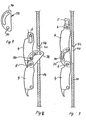
- 1-4 show an embodiment of the inventive guiding of the roller shutter curtain in side view or in section.
- Several horizontal slats 4 are attached to tension elements 5 and form the roller shutter curtain.
- the lamellae have horizontal pins 6 on their end faces, which are rotatably mounted on the traction elements about their horizontal axis, e.g. made of ribbons, textiles or metal.
- the pins 6 are guided in vertical guide rails 10 between two guide webs 12, 14 each.
- the guide webs 12, 14 form a guide gap 13 for the pins 6.
- the guide rails 10 have approximately a square or rectangular cross section.
- the fixed guide web 14 represents a wall of the guide rail 10, which runs parallel behind the curtain 4 and is usually connected to the window frame or the masonry.
- a second wall 15 of the guide rail 10 adjoins the first guide web 14 perpendicularly thereto, which merges into a third wall 17 which runs parallel to the first guide web 14.
- a double wall section 18 adjoins the third wall 17 of the guide rail perpendicularly and is directed towards the first guide web 14 and ends a predetermined distance in front of the guide web 14.
- a guide web 12 is slidably arranged, which extends the double wall section 18 in the direction of the fixed guide web 14. Between the guide webs 12, 14 there is the guide gap 13.
- the movable guide web 12 has recesses 19 directed obliquely downwards against the fixed guide web 14, through which a pin 16 protrudes, which is fastened in the double wall section 18.
- Recesses 19 and pins 16 form a positive guide for the movable web 12, which, under its own weight - guided by the pin 16 and the recess 19 - runs obliquely downward against the fixed guide web 14 until the free edge of the guide web 12 on the pin 6 of the slats 4 abuts and exerts a predetermined contact pressure on the pin 6.
- the horizontal slats 4 can all be pivoted about horizontal axes from a predetermined upper slat e.g. articulated by means of the pins 6 on the traction elements 5 and connected by means of additional turning elements (not shown) to form a lamella swivel joint.
- the slat swivel assembly can be swiveled from a roller shutter position, in which the slats hang in the curtain level, into a blind position in which the individual slats are pivoted out of the plane of the pulling elements 5 parallel to one another, cf. 3 and 4.
- the front pins 6 of the slats 4 have an oval cross section, the long axis of which is approximately vertical with hanging slats.
- the pins 6 push the movable guide web 12 obliquely upwards against its own weight.
- the movable web 12 presses constantly against the pin 6 and thereby forms a means which prevents unwanted wind movements and wind noise from the slats or the pin.
- FIG. 5 and 6 show a coupling arrangement between the curtain of the roller shutter and the displaceable guide web 12.
- This coupling arrangement causes the curtain from the slats 4 to positively grip the displaceable guide web 12 when the lower end position is reached and with its weight against the pins 6 of the slats 4 presses into a lower rest position, so that the weight of the curtain supports the hold-down effect of the displaceable guide web 12 with its own weight.
- the displaceable guide web 12 has at its lower end a pin-shaped extension 12a which is fastened perpendicularly to the guide web 12 and runs parallel to the pin 6.
- the lower end lamella 4a has an extension 4b at the outer end of the pin 6, which has a downwardly open and widening recess 4c and is guided in the guide rail 10.
- the pin 12a of the guide web 12 is caught in the recess 4c and pressed by the weight of the curtain into a lower rest position, in which the guide web 12 presses against the pins 6 of the slats 4 and the slats - due to the rectangular pin - holds under the effect of the weight of the guide bar and the weight of the curtain in the closed position.
- the recess 4c has an obliquely outwardly directed contact surface 4d, which then abuts against the pin 12a of the guide web 12 when the guide web 12 has tilted in an upper position or is otherwise fixed.
- the pin 12a then runs along the inclined contact surface 4d into the lower rest position.
- a predetermined upper lamella 4 which comes to rest in the upper end of the guide rails 10 when the curtain is completely closed, has an additional coupling pin 30 under each of its front pins 6.
- a coupling plate 32 is provided on the front side, which has a convex shape has outwardly curved coupling gap 34 for receiving the coupling pin.
- an eye 36 in the coupling plate for receiving the pin of the underlying lamella 4.
- a recess 40 is provided in the fixed guide web 14 at the lower end position of the coupling plate 32, the upper edge 42 of which is above the coupling plate 32 lies.
- the coupling pin 30 is located approximately vertically above the eye 36 at the upper end of the coupling gap 34.
- the rear edge of the coupling plate 32 then extends approximately vertically.
- the upper part 38 of the coupling plate snaps behind the upper edge 32 of the recess 40 and thereby prevents the curtain from moving further upward.
- the curtain can only be moved up again by pulling on the lamellae lying above the coupling plates, because when a corresponding tensile force is applied, the coupling pin 30 runs to the upper end of the coupling gap 34 and thereby swings the coupling plate 32 out of the recess 40.
- FIG. 9 shows a detailed view of the coupling plate 32 from FIGS. 7 and 8.
- the coupling shaft 34 which is convexly curved outwards, for receiving a coupling pin 30 is clearly recognizable.
- An eye 36 lies below the upper end of the coupling gap 34, approximately in extension of the center line of the coupling gap 34 which serves to receive the pin of the lower slat 4 to be coupled.
Landscapes
- Engineering & Computer Science (AREA)
- Structural Engineering (AREA)
- Architecture (AREA)
- Civil Engineering (AREA)
- Operating, Guiding And Securing Of Roll- Type Closing Members (AREA)
- Liquid Crystal (AREA)
- Window Of Vehicle (AREA)
- Pinball Game Machines (AREA)
- Specific Sealing Or Ventilating Devices For Doors And Windows (AREA)
Claims (11)
Priority Applications (1)
| Application Number | Priority Date | Filing Date | Title |
|---|---|---|---|
| AT81109569T ATE8808T1 (de) | 1980-11-18 | 1981-11-07 | Rolladen. |
Applications Claiming Priority (2)
| Application Number | Priority Date | Filing Date | Title |
|---|---|---|---|
| DE19803043480 DE3043480A1 (de) | 1980-11-18 | 1980-11-18 | Rolladen |
| DE3043480 | 1980-11-18 |
Publications (2)
| Publication Number | Publication Date |
|---|---|
| EP0052320A1 EP0052320A1 (fr) | 1982-05-26 |
| EP0052320B1 true EP0052320B1 (fr) | 1984-08-01 |
Family
ID=6117055
Family Applications (1)
| Application Number | Title | Priority Date | Filing Date |
|---|---|---|---|
| EP81109569A Expired EP0052320B1 (fr) | 1980-11-18 | 1981-11-07 | Volet à rouleau |
Country Status (3)
| Country | Link |
|---|---|
| EP (1) | EP0052320B1 (fr) |
| AT (1) | ATE8808T1 (fr) |
| DE (2) | DE3043480A1 (fr) |
Cited By (1)
| Publication number | Priority date | Publication date | Assignee | Title |
|---|---|---|---|---|
| AT394030B (de) * | 1990-07-27 | 1992-01-27 | Naintsch Mineralwerke | Reinigung von oel- und fettbeladenem abwasser |
Families Citing this family (10)
| Publication number | Priority date | Publication date | Assignee | Title |
|---|---|---|---|---|
| ATA206486A (de) * | 1986-07-31 | 1991-06-15 | Franz Gertl | Rolladen |
| AT393869B (de) * | 1986-07-31 | 1991-12-27 | Franz Gertl | Rolladen |
| IT1265956B1 (it) * | 1993-11-08 | 1996-12-16 | Quinto Giovanetti | Inferriata mobile per le finestre abbinabile alle persiane avvolgibili |
| EP0667441A1 (fr) * | 1994-02-15 | 1995-08-16 | Sui Kuo Cheng | Volet enroulable en acier |
| CH693575A5 (de) * | 1999-06-04 | 2003-10-15 | Schenker Storen Ag | Blockiervorrichtung an einer Endschiene einer Raff-Lamellenstore. |
| NL1018406C1 (nl) | 2001-06-28 | 2003-01-16 | Aldon B V | Zonwering. |
| US20040188037A1 (en) | 2003-03-31 | 2004-09-30 | Creative Extruded Products, Inc. | Retention system for pivotally connected shutter slats |
| DE102004048252B3 (de) * | 2004-10-04 | 2006-05-24 | Peter Bichler | Jalousierbarer Rollladen und Glied dafür |
| ZA200803216B (en) * | 2006-04-25 | 2010-02-24 | Primic Louis Andre | Roller shutter |
| AU2015238412B2 (en) * | 2014-03-25 | 2019-01-17 | Assa Abloy Entrance Systems Ab | Roller shutter for opening and closing a doorway |
Family Cites Families (7)
| Publication number | Priority date | Publication date | Assignee | Title |
|---|---|---|---|---|
| DE7507323U (de) * | 1975-06-26 | Muhs H | Vorrichtung zum Festklemmen von Rolläden | |
| DE8275C (de) * | J. BONNET in Berlin | Feststellvorrichtung für Brettchen- und andere Fenster-Vorhänge | ||
| DE1260113B (de) * | 1958-02-15 | 1968-02-01 | Jaime Colom Grau | Einrichtung zum jalousieartigen Verstellen von Rolladenstaeben |
| DE1509864A1 (de) * | 1964-02-15 | 1969-07-10 | Schneider Ohg Geb | Rolladen mit Schwenkstaeben |
| DE1910198A1 (de) * | 1969-02-28 | 1970-09-17 | Vladislav Novak | Jalousie fuer Fenster,Tueren od.dgl. |
| DE2220433C3 (de) * | 1972-04-26 | 1975-06-26 | Rudolf 5765 Langscheid Kempa | Arretiervorrichtung für Roll- oder Faltläden zwecks Vermeidens von Geräuschentwicklung bei Wind, Erschütterungen od.dgl |
| DE7818537U1 (de) * | 1978-06-21 | 1978-09-28 | Gust. Alberts Gmbh & Co Kg, 5974 Herscheid | Befestigungslasche fuer eine rolladensicherungsvorrichtung |
-
1980
- 1980-11-18 DE DE19803043480 patent/DE3043480A1/de not_active Withdrawn
-
1981
- 1981-11-07 DE DE8181109569T patent/DE3165273D1/de not_active Expired
- 1981-11-07 AT AT81109569T patent/ATE8808T1/de not_active IP Right Cessation
- 1981-11-07 EP EP81109569A patent/EP0052320B1/fr not_active Expired
Cited By (1)
| Publication number | Priority date | Publication date | Assignee | Title |
|---|---|---|---|---|
| AT394030B (de) * | 1990-07-27 | 1992-01-27 | Naintsch Mineralwerke | Reinigung von oel- und fettbeladenem abwasser |
Also Published As
| Publication number | Publication date |
|---|---|
| EP0052320A1 (fr) | 1982-05-26 |
| DE3043480A1 (de) | 1982-07-08 |
| ATE8808T1 (de) | 1984-08-15 |
| DE3165273D1 (en) | 1984-09-06 |
Similar Documents
| Publication | Publication Date | Title |
|---|---|---|
| DE69518742T2 (de) | Overhead door and track therefor | |
| EP0052320B1 (fr) | Volet à rouleau | |
| CH659284A5 (de) | Faltwand. | |
| DE69328827T2 (de) | Schiebefenster, bestehend aus mindestens einem rahmen mit einem darin vertikal verschiebbaren flügel | |
| DE69515999T2 (de) | Aufhängevorrichtung für eine türkonstruktion | |
| DE69506325T2 (de) | Verschlusseinrichtung | |
| DE2856171A1 (de) | Faltbare tuer oder wand | |
| DE4204267A1 (de) | Horizontal-rolltor | |
| EP0093695B1 (fr) | Store vénitien à rouleau et dispositif pour l'arrêter pendant le mouvement descendant | |
| DE4014106C2 (de) | Bodendichtungsleiste für eine Drehflügeltür | |
| EP2677100A2 (fr) | Installation de porte coulissante | |
| DE841634C (de) | Schiebetor, insbesondere fuer grosse OEffnungen | |
| DE19618912A1 (de) | Lamelle für ein Blatt eines vorzugsweise auf und ab bewegbaren Rollverschlusses für ein Tor, eine Tür, ein Fenster o. dgl. Öffnung | |
| DE4226702C2 (de) | Dichtungsvorrichtung für den unteren Spalt einer Tür | |
| AT411088B (de) | Stab für verschiebbare, öffnungen zugeordnete vorrichtungen, wie rollläden | |
| DE19713901A1 (de) | Schieberolltor zum Verschließen einer Durchgangsöffnung | |
| DE2920124C2 (de) | Lamellenjalousie für Gebäudeöffnungen, insbesondere Fensteröffnungen | |
| CH392838A (de) | Fenster- oder Türladen, insbesondere Schiebeladen | |
| DE3911187A1 (de) | Hebekippfenster | |
| DE1459209A1 (de) | Beschlag fuer wahlweise um eine lotrechte seitliche Achse schwenkbare oder um eine waagerechte untere Achse kippbare Fluegel von Fenstern,Tueren od. dgl. | |
| EP1437469A1 (fr) | Fenêtre | |
| DE10100834C2 (de) | Beschlag für Sektionaltor | |
| DE146723C (fr) | ||
| DE3106537C2 (fr) | ||
| DE659849C (de) | Faltschiebetor aus mehreren paarweise durch Gelenke miteinander verbundenen Tortafeln |
Legal Events
| Date | Code | Title | Description |
|---|---|---|---|
| PUAI | Public reference made under article 153(3) epc to a published international application that has entered the european phase |
Free format text: ORIGINAL CODE: 0009012 |
|
| AK | Designated contracting states |
Designated state(s): AT BE CH DE FR GB IT LI LU NL SE |
|
| 17P | Request for examination filed |
Effective date: 19820612 |
|
| RAP1 | Party data changed (applicant data changed or rights of an application transferred) |
Owner name: HUEPPE GMBH |
|
| ITF | It: translation for a ep patent filed | ||
| GRAA | (expected) grant |
Free format text: ORIGINAL CODE: 0009210 |
|
| AK | Designated contracting states |
Designated state(s): AT BE CH DE FR GB IT LI LU NL SE |
|
| PG25 | Lapsed in a contracting state [announced via postgrant information from national office to epo] |
Ref country code: SE Effective date: 19840801 |
|
| REF | Corresponds to: |
Ref document number: 8808 Country of ref document: AT Date of ref document: 19840815 Kind code of ref document: T |
|
| REF | Corresponds to: |
Ref document number: 3165273 Country of ref document: DE Date of ref document: 19840906 |
|
| ET | Fr: translation filed | ||
| PGFP | Annual fee paid to national office [announced via postgrant information from national office to epo] |
Ref country code: FR Payment date: 19841114 Year of fee payment: 4 |
|
| PG25 | Lapsed in a contracting state [announced via postgrant information from national office to epo] |
Ref country code: LU Free format text: LAPSE BECAUSE OF NON-PAYMENT OF DUE FEES Effective date: 19841130 |
|
| PGFP | Annual fee paid to national office [announced via postgrant information from national office to epo] |
Ref country code: BE Payment date: 19841231 Year of fee payment: 4 |
|
| PLBE | No opposition filed within time limit |
Free format text: ORIGINAL CODE: 0009261 |
|
| STAA | Information on the status of an ep patent application or granted ep patent |
Free format text: STATUS: NO OPPOSITION FILED WITHIN TIME LIMIT |
|
| 26N | No opposition filed | ||
| PGFP | Annual fee paid to national office [announced via postgrant information from national office to epo] |
Ref country code: AT Payment date: 19861127 Year of fee payment: 6 |
|
| PGFP | Annual fee paid to national office [announced via postgrant information from national office to epo] |
Ref country code: NL Payment date: 19871130 Year of fee payment: 7 |
|
| PG25 | Lapsed in a contracting state [announced via postgrant information from national office to epo] |
Ref country code: GB Effective date: 19881107 Ref country code: AT Effective date: 19881107 |
|
| PG25 | Lapsed in a contracting state [announced via postgrant information from national office to epo] |
Ref country code: BE Effective date: 19881130 |
|
| BERE | Be: lapsed |
Owner name: HUPPE G.M.B.H. Effective date: 19881130 |
|
| PG25 | Lapsed in a contracting state [announced via postgrant information from national office to epo] |
Ref country code: NL Effective date: 19890601 |
|
| NLV4 | Nl: lapsed or anulled due to non-payment of the annual fee | ||
| GBPC | Gb: european patent ceased through non-payment of renewal fee | ||
| PG25 | Lapsed in a contracting state [announced via postgrant information from national office to epo] |
Ref country code: FR Free format text: LAPSE BECAUSE OF NON-PAYMENT OF DUE FEES Effective date: 19890731 |
|
| REG | Reference to a national code |
Ref country code: FR Ref legal event code: ST |
|
| PGFP | Annual fee paid to national office [announced via postgrant information from national office to epo] |
Ref country code: CH Payment date: 19961126 Year of fee payment: 16 |
|
| PG25 | Lapsed in a contracting state [announced via postgrant information from national office to epo] |
Ref country code: LI Free format text: LAPSE BECAUSE OF NON-PAYMENT OF DUE FEES Effective date: 19971130 Ref country code: CH Free format text: LAPSE BECAUSE OF NON-PAYMENT OF DUE FEES Effective date: 19971130 |
|
| REG | Reference to a national code |
Ref country code: CH Ref legal event code: PL |
|
| PGFP | Annual fee paid to national office [announced via postgrant information from national office to epo] |
Ref country code: DE Payment date: 19991201 Year of fee payment: 19 |
|
| PG25 | Lapsed in a contracting state [announced via postgrant information from national office to epo] |
Ref country code: DE Free format text: LAPSE BECAUSE OF NON-PAYMENT OF DUE FEES Effective date: 20010801 |