EP0052324A2 - Mélangeur magnétique - Google Patents
Mélangeur magnétique Download PDFInfo
- Publication number
- EP0052324A2 EP0052324A2 EP81109578A EP81109578A EP0052324A2 EP 0052324 A2 EP0052324 A2 EP 0052324A2 EP 81109578 A EP81109578 A EP 81109578A EP 81109578 A EP81109578 A EP 81109578A EP 0052324 A2 EP0052324 A2 EP 0052324A2
- Authority
- EP
- European Patent Office
- Prior art keywords
- pole
- base
- magnetic
- pole shoes
- shoes
- Prior art date
- Legal status (The legal status is an assumption and is not a legal conclusion. Google has not performed a legal analysis and makes no representation as to the accuracy of the status listed.)
- Granted
Links
Images

Classifications
-
- H—ELECTRICITY
- H02—GENERATION; CONVERSION OR DISTRIBUTION OF ELECTRIC POWER
- H02K—DYNAMO-ELECTRIC MACHINES
- H02K7/00—Arrangements for handling mechanical energy structurally associated with dynamo-electric machines, e.g. structural association with mechanical driving motors or auxiliary dynamo-electric machines
- H02K7/08—Structural association with bearings
- H02K7/09—Structural association with bearings with magnetic bearings
-
- B—PERFORMING OPERATIONS; TRANSPORTING
- B01—PHYSICAL OR CHEMICAL PROCESSES OR APPARATUS IN GENERAL
- B01F—MIXING, e.g. DISSOLVING, EMULSIFYING OR DISPERSING
- B01F33/00—Other mixers; Mixing plants; Combinations of mixers
- B01F33/45—Magnetic mixers; Mixers with magnetically driven stirrers
- B01F33/452—Magnetic mixers; Mixers with magnetically driven stirrers using independent floating stirring elements
-
- H—ELECTRICITY
- H05—ELECTRIC TECHNIQUES NOT OTHERWISE PROVIDED FOR
- H05B—ELECTRIC HEATING; ELECTRIC LIGHT SOURCES NOT OTHERWISE PROVIDED FOR; CIRCUIT ARRANGEMENTS FOR ELECTRIC LIGHT SOURCES, IN GENERAL
- H05B6/00—Heating by electric, magnetic or electromagnetic fields
- H05B6/02—Induction heating
- H05B6/34—Arrangements for circulation of melts
-
- H—ELECTRICITY
- H05—ELECTRIC TECHNIQUES NOT OTHERWISE PROVIDED FOR
- H05B—ELECTRIC HEATING; ELECTRIC LIGHT SOURCES NOT OTHERWISE PROVIDED FOR; CIRCUIT ARRANGEMENTS FOR ELECTRIC LIGHT SOURCES, IN GENERAL
- H05B2213/00—Aspects relating both to resistive heating and to induction heating, covered by H05B3/00 and H05B6/00
- H05B2213/02—Stirring of melted material in melting furnaces
Definitions
- the invention relates to a magnetic stirring device with a base which serves to support a vessel containing the liquid to be stirred and a magnetic stirring rod and which contains an electromagnet arrangement, the poles of which lie opposite one another in a plurality of pairs on the top or front side of the base are located and the excitation windings for generating a magnetic field of variable size prevailing at the individual poles can be supplied with current.
- Such a device is known from German Offenlegungsschrift 27 09 365 and contains, as an electromagnet arrangement, mutually opposed coils whose magnetic fields generated by alternating current supply of the coils, in cooperation, set the stirring rod in rotation.
- the known device has the disadvantage that a stable, contactless mounting of the stirring rod within the vessel containing the liquid to be stirred is not always possible during operation, that the centering of the stirring rod, in particular when starting up the device, causes difficulties and that, in particular, the range of usable stirring rod lengths is very limited, which limits the possible application speed of the known stirring device.
- the object of the invention is to enable stable operation with stirrers of different lengths and to generate large force effects.
- This object is achieved according to the invention in a stirring device of the type described in the introduction in that the poles of a pair of poles have radially elongated pole shoes in supervision with respect to a common center.
- poles of all pole pairs are expediently provided with pole shoes, with either only one pole shoe pair having the aforementioned elongated shape or all pole shoe pairs being elongated in the radial direction.
- the pole pieces elongated in the radial direction with respect to the common center can have an approximately triangular or approximately elongated teardrop-shaped supervisory shape.
- the shaping of the pole shoes leads to an increase in the achievable force on the stirring rod.
- This force effect can be further increased if, according to an expedient development, mutually opposing pairs of pole pieces are connected to one another via a common core located in the base and approximately U-shaped in cross section, on which excitation windings respectively associated with the pole pieces sit.
- the pole shoes can either be flush with their top lie in a support surface of the base or lie directly under an encapsulation of the base made of non-magnetic material, in particular plastic or stainless steel. This simplifies keeping the base of the device clean and enables the vessel containing the liquid to be stirred to be put on without interference.
- the P can ol mortis respectively on of magnetically active material-made connectors to be secured, which extend approximately in the vertical direction towards the base and are part of the solenoid assembly or each of which is bent out to the vertical to be supported base. With their ends remote from the pole pieces, these connecting pieces are anchored in the base.
- connecting pieces protrude vertically from the base, it is possible to place a device with the liquid to be stirred between the connecting pieces underneath the vessel supported by the pole pieces, for example a nozzle providing cooling air or a Bunsen burner used to heat the liquid.
- a device with the liquid to be stirred between the connecting pieces underneath the vessel supported by the pole pieces for example a nozzle providing cooling air or a Bunsen burner used to heat the liquid.
- the base from a section containing the excitation windings and parts of a core arrangement coupled thereto and a section detachably connected to it and holding the pole shoes or their connecting pieces.
- This training facilitates the manufacture of the device and its assembly.
- various sections, which hold the pole shoes or their connecting pieces with a single unit, which contains the excitation windings and parts of the core arrangement, according to the modular principle.
- the excitation windings of the magnet arrangement are each controlled with square wave supply voltages in the device proposed here in such a way that the excitation windings of diametrically opposite poles experience phase excitation, while the excitation windings of a pole pair spatially offset by 90 ° with a square wave that is electrically phase-shifted by 90 ° for this purpose be charged.
- This control of the excitation windings has proven to be very advantageous for achieving stable operation and for immediate centering of the magnetic stir bar during commissioning.
- the invention also includes the multiplication of the proposed magnetic stirring device into stirring plate-like arrangements, which, when the magnetic arrangements of the individual devices are controlled synchronously, has further areas in which a stirring rod located in a vessel with liquid causes rotation becomes.
- the known magnetic stirring devices sometimes have the disadvantage that the magnetic fields which are to interact with the magnetic stirring rod are not sufficiently strong and do not enable stable stirring operation, so that it can occur that in the When the excitation of the magnetic coils is switched on, the liquid magnetic stirring bar does not start rotating or only starts with a considerable delay, tends to hit or runs repeatedly from the center.
- the aforementioned goal is achieved in that the pole pieces of the magnetic coils located in the plane of the base top cover this base top to such an extent that comparatively narrow gap spaces are provided between the pole pieces. It is seen that also in this case, the basic idea is satisfied, the P ol shoes a large extent in the radial direction towards a center to give out.
- At least the pole pieces can be embedded in plastic in such a way that the pole piece surfaces and the plastic filling of the gap spaces in the base surface are aligned.
- the entire base is preferably cast in plastic.
- the outer coil diameter can be slightly smaller than the diagonal of the pole shoes, which are square when viewed from above. It can be seen that in the case of a square shape of the pole pieces, the interspaces between the gaps determine a square grid, the crossover points of which are those points on the base top side on which the vessels can be placed with a magnetic stirring rod for the purpose of stirring their contents. In a rectangular arrangement with magnetic coils in a square grid arrangement, there are a large number of stirring points without having to provide four times the number of stirring points as the number of magnetic coils.
- the base can contain a yoke arrangement which carries iron cores of the magnetic coils and which can have the shape of a soft iron plate.
- the Jochanordnunq can, however, also be a soft iron grid connecting the base points of iron cores of the magnet coil.
- pole pieces and associated magnet coils provide that the pole pieces essentially each have the shape of regular trapezoids as parts of equilateral triangles and that the gap spaces between the pole pieces determine a regular hexagon pattern and the base points of the iron cores of the magnet coils at the crossing points of a smaller scale compared to the offset hexagon grid.
- each pole piece and each associated solenoid coil belongs simultaneously to two stirring points.
- a certain number of stirring points, each containing six pole pieces can thus be achieved by providing a smaller number of pole pieces than six times the number of stirring points.
- a further improvement in the centering behavior and the stability of the stirring rod position in operation is achieved even with widely differing rod lengths in that the ra with reference to a common center dial elongated pole pieces are cranked upward from their respective connection point to the magnet coil poles in such a way that radially inner pole piece sections are located essentially in one plane with the storage surface for the vessels or immediately below, while the pole piece sections connected to the magnet coil poles are at a greater distance from the Level of the footprint are located below this.
- the stray fields emanating from the magnetic coil poles have a comparatively high intensity to a lesser extent on the stirring rod ends.
- care is taken to ensure that the magnetic coil poles are set back relative to the storage surface of the base, while the radially inner pole shoe sections generate a central rotating field of high intensity, which interacts with the stirring rod and centers the stirring rod.
- the invention also encompasses the use of the proposed magnetic stirring device for household purposes.
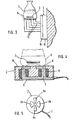
- an approximately circular disk-shaped base of the stirring device is designated by 1.
- the stirring rod 2 which has a magnetic moment and can be formed, for example, by a plastic-coated magnetic rod, is located in a vessel 3, indicated by dash-dotted lines in FIG. 1, which is placed on the top of the base 1.
- the vertical limbs 5 merge at their upper ends into pole pieces 8 which, when viewed from above, have an elongated egg-shaped, elongated teardrop-shaped or pointed triangular shape.
- the narrow or s p it- zen ends of the pole shoes have a common Z ene towards spectrum.
- the upper sides of the pole shoes 8 lie flush in the upward-facing surface 9 of a flat disk-shaped part or section 10 of the base 1, the section 10 adjoining a lower section 12 of the base via a parting line 11.
- the parting line 11 extends through the entire arrangement, including the vertical legs 5 of the electromagnet arrangement, such that the base sections 10 and 12 can be releasably clamped together.
- the P ol shoes 8 part of the section 10 of the base 1 form the pole shoes 8 in the embodiment of figure 2 at the upper ends of of magnetically active material manufactured connectors 13 are fixed, which lower their Ends are anchored in the section 10 of the base and abut the upper ends of the vertical legs 5 of the core 4 of the magnet arrangement.
- the connecting pieces 13 thus represent extensions of the magnetic closing circuits in such a way that a vessel 3 containing a liquid and the stirring rod 2 can be supported at a certain height above the upper side 9 of the base 1.
- the vessel is supported by the pole shoes 8 alone or in cooperation with additional holding and supporting means.
- Bunsen burner 14 can be placed between the connecting pieces 13 on the base 1, by means of which the contents of the vessel 3 can be heated by means of the stirring rod 2 during stirring.
- the connecting pieces 13 can also each be angled and with a horizontal section in the vertically standing base 1 or the A b-section 10 of the latter must be anchored.
- the different lengths of the connecting pieces 13 in this case are of no importance magnetically because of the incomparably higher magnetic resistance of the gap space between the pole shoes 8 and the stirring rod 2.
- the embodiment according to FIG. 4 is similar to that according to FIG. 1, but the upper sides of the pole shoes 8 are not exposed on the upper side 9 of the base 1, but are located directly below an encapsulation 15 of the base 1, this encapsulation being made of plastic, for example tetrafluoroethylene, or can be made of non-magnetic, stainless steel.
- the enclosure 15 is chosen with regard to thickness and in material so that the formation of the R 2 mmstab influencing the magnetic field is not substantially impeded.
- the arrangement can otherwise be such that the electromagnet assembly and the pole pieces 8 are cast in plastic after preparatory assembly within the base 1.
- the magnetic stirring device shown in top view in FIG. 5 has, in the rest of the similar design as the devices according to FIGS. 1 and 4, different pairs of opposing pole shoes.
- the shape of the pole shoe pair 8a corresponds to the shape of the pole shoes 8 of the previously described embodiments.
- the pair of pole pieces 8b spatially offset by 90 ° has the shape of comparatively wide circular sector structures when viewed from above.
- the excitation windings assigned to the pole shoe pairs 8a and 8b are controlled by square wave supply voltages at a frequency corresponding to the desired speed of the stirring rod with a mutual phase shift corresponding to the spatial offset of the pole shoe pairs, in the present example with a phase shift of 90 °.
- a similar feeding of the excitation windings is also provided in the previously described embodiments.
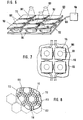
- the magnetic stirring device according to FIG. 6 contains a flat plate-shaped base 101 which is built on a yoke arrangement 102 in the form of a soft iron plate. As indicated in the left part of the illustration in FIG. 6, iron cores 103, which are surrounded by flat, disk-shaped magnetic coils 104, protrude from the soft iron plate 102 at points determined by a square grid.
- the magnetic coils are connected to a current source 106 via connecting lines 105; which allows the magnetic coils to be supplied with currents which are phase-shifted relative to one another, so that above the magnetic coils, in a layer parallel to the base 101, magnetic rotating fields are created which interact with a magnetic stirring rod 101, which is located in a vessel 108 which holds the Contains liquid to be stirred and out on the base top represents is.
- the manner in which the current is applied to generate suitable rotating magnetic fields is not the subject of the invention and is known to the person skilled in the art.
- the magnetic stirring device can have a base 101, each with more than two rows and more than two columns of coils, as can be seen from FIG. The meaning of this arrangement is described in more detail below.
- the base 101 according to FIG Pole shoes 109 are filled with plastic.
- the entire base 101 can, however, also be completely encapsulated with plastic, so that the pole shoes 109 are embedded in the plastic on the upper side of the base.
- the pole shoes 109 are dimensioned such that they have a diagonal which is somewhat larger than the diameter of the coils 104. In this way, it is avoided that excessive magnetic stray fluxes to the yoke arrangement 102 occur due to excessive overlap of the pole shoes via the coils.
- a larger number of stirring points based on a magnetic stirring device can be realized not only by a row and gap arrangement of rectangular and in particular square pole shoes 109, but also by a plurality of equilateral triangular or trapezoidal pole shoes, as shown in FIG. 8.
- the magnet arrangement formed from four magnet coils 104 and four associated pole pieces 109 for generating a magnetic rotating field in the layer space above the base top side thus contains two pole pairs in the embodiments according to FIGS. 6 and 7 in the form of diagonally opposite one another via a crossing point of the gap spaces 110 Pole shoes, while in the embodiment according to FIG. 8 three pairs of poles are provided, each of which generates such a magnetic rotating field on account of phase-shifted excitation of the magnetic coils.
- the individual pole pieces are designated 111 and have the shape of regular trapezoids, the long sides of which are aligned along a hexagon pattern, as indicated in Figure 8 at 112 by dash-dotted lines. Magnetic coils are located below the pole pieces 111, but are not shown in FIG. 8 to simplify the illustration.
- the stirring points which are again at the crossing points of the gap spaces 110, are 113 in FIG. 8 designated. They lie at the branching points of the hexagon pattern 112 and are formed by the crossover points of the gap spaces 110.
- the hexagon pattern 112 has a regular shape, while when the trapezoidal pole pieces 111 are parts of isosceles triangles, which have different vertex angles that are to be determined according to simple geometric considerations have the hexagon pattern 112 stretchable in one direction or another, which may be desirable in certain cases. Also applies to the magnetic stirrer according to FIG. 8 that a larger number of stirring points can be created due to the fact that each pole piece belongs to two stirring points 113 than is obtained by dividing the number of pole pieces used by six.
- the embodiment according to FIG. 9 initially differs from that according to FIG. 6 in that, instead of the yoke arrangement 102 in the form of a soft iron plate, a grid arrangement 114 is used in the embodiment according to FIG. 9, the grid bars of which are arranged in the manner of a square grid or rectangular grid between the base points of the iron cores 103 of the solenoids extend.
- the square-shaped pole pieces 109 are provided with radial indentations or cutouts in the middle of their square sides, such that such cutouts designated by 115 in FIG. 9 face each other across the gap spaces 110 between the pole pieces 109.
- the clear space determined by a pair of cutouts 115 is of such a length that its vertical projection onto one leg of the grating 114 falls, whereby the formation of stray fluxes between the pole shoes 109 and the grid 114 and thus a weakening of the magnetic field above the storage surface of the base is avoided.
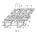
- the magnetic stirring device shown in FIG. 10 contains a base 201 which is accommodated in a housing (not shown) and which, which is also not shown, can be cast, for example, in casting resin.
- the base has a yoke plate 202 on which solenoids 203, 204, 205 and 206 are mounted.
- the cores of the magnetic coils 203 to 206 are fixed on the one hand to the yoke plate 202 and on the other hand are connected to pole shoes 207 or 208 or 209 or 210, which are elongated radially with respect to a common center or the center 211 of the relevant storage surface.
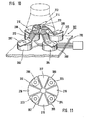
- the pole shoes 207 to 210 are cranked upward from their respective connection point to the solenoid coils, as is made clear at 212 in FIG. 10.
- the radially inner pole piece sections accordingly lie essentially in one plane with the storage surface for placing a vessel 213 indicated by a dot-dash line with a stirring rod 214 therein, while the pole shoe sections connected to the magnet coil poles, that is to say the radially outer pole piece parts, are located at a greater vertical distance below the storage surface.
- the pole shoes have a wedge-shaped shape in the region of their radially inner ends, so that only comparatively narrow spaces are provided between the pole shoes.
- the pole shoe arrangement shown in top view in FIG. 11 contains two pairs of opposing pole shoes 207 to 210.
- the pole shoes have an essentially circular sector shape.
- fillers 215, 216, 217 and 218 which are made of magnetically active material and which fill this gap apart from narrow gap spaces are provided in the gap between the pole shoes.
- the filler pieces have the same shape as the pole pieces and, in the embodiment according to FIG. 11, lie in one plane with these pole pieces. In certain cases, however, it is advantageous to place the fillers 215 to 218 somewhat lower than the plane of the pole shoes 207 to 210. Do the pole shoes 07 to 210 of the embodiment according to FIG. 11 have an upward offset, as they together. 10 has been described, it may be useful, for example, to arrange the fillers 215 to 218 in the plane of those pole piece sections which are connected to the magnet coil poles.
- the fillers 215 to 218 increase the stability of the operation at low speeds and enable a higher stirring force.
- FIGS. 10 and 11 are of course only shown in a highly schematic manner.
- the excitement of the magnet Coils 203 to 206 by a current source indicated as a block symbol in FIG. 10 is carried out in such a way that a rotating magnetic field with a vector rotating in the plane of this parking area is generated in the parking area of the base 201 in a manner known per se.
- a corresponding enlargement of the base results in several stirring points for the simultaneous operation of several stirring rods in a corresponding number of vessels.
- the yoke plate 202 and the radially outer ends of the pole shoes are shown broken off or cut off in FIG.
Landscapes
- Engineering & Computer Science (AREA)
- Power Engineering (AREA)
- Chemical & Material Sciences (AREA)
- Chemical Kinetics & Catalysis (AREA)
- Physics & Mathematics (AREA)
- Electromagnetism (AREA)
- Mixers With Rotating Receptacles And Mixers With Vibration Mechanisms (AREA)
Applications Claiming Priority (6)
| Application Number | Priority Date | Filing Date | Title |
|---|---|---|---|
| DE19803043335 DE3043335A1 (de) | 1980-11-17 | 1980-11-17 | Magnet-ruehreinrichtung |
| DE3043335 | 1980-11-17 | ||
| DE19818106555 DE8106555U1 (de) | 1981-03-07 | 1981-03-07 | Magnet-ruehreinrichtung |
| DE8106555U | 1981-03-07 | ||
| DE19813135961 DE3135961A1 (de) | 1981-09-10 | 1981-09-10 | Magnet-ruehreinrichtung |
| DE3135961 | 1981-09-10 |
Publications (3)
| Publication Number | Publication Date |
|---|---|
| EP0052324A2 true EP0052324A2 (fr) | 1982-05-26 |
| EP0052324A3 EP0052324A3 (en) | 1983-05-18 |
| EP0052324B1 EP0052324B1 (fr) | 1986-03-05 |
Family
ID=27188960
Family Applications (1)
| Application Number | Title | Priority Date | Filing Date |
|---|---|---|---|
| EP81109578A Expired EP0052324B1 (fr) | 1980-11-17 | 1981-11-09 | Mélangeur magnétique |
Country Status (2)
| Country | Link |
|---|---|
| US (1) | US4568195A (fr) |
| EP (1) | EP0052324B1 (fr) |
Cited By (3)
| Publication number | Priority date | Publication date | Assignee | Title |
|---|---|---|---|---|
| GB2158059A (en) * | 1984-04-25 | 1985-11-06 | Emil Albert Schaerer | Device for reducing the surface tension of water |
| EP0154112A3 (en) * | 1984-01-11 | 1986-05-07 | Helmut Dipl.-Ing. Herz | Magnetic stirring device |
| EP0345569A3 (fr) * | 1988-06-04 | 1991-01-09 | Sartorius Ag | Balance électronique à plateaux supérieurs |
Families Citing this family (56)
| Publication number | Priority date | Publication date | Assignee | Title |
|---|---|---|---|---|
| US5025927A (en) * | 1985-10-03 | 1991-06-25 | Garg Raj P | Respirometer |
| US4783172A (en) * | 1985-10-03 | 1988-11-08 | Garg Raj P | Respirometer |
| US5125262A (en) * | 1985-10-03 | 1992-06-30 | Garg Raj P | Method of determining oxygen demand of a liquid |
| KR0138254B1 (ko) * | 1989-03-10 | 1998-04-27 | 니시오카 시게루 | 교반장치 |
| US4911556A (en) * | 1989-03-17 | 1990-03-27 | Lim Technology Laboratories, Inc. | Turbulent stirring unit |
| BR9100477A (pt) * | 1991-01-30 | 1992-09-22 | Brasil Compressores Sa | Dispositivo de partida para motor a inducao monofasico |
| FR2679660B1 (fr) * | 1991-07-22 | 1993-11-12 | Pasteur Diagnostics | Procede et dispositif magnetique d'analyse immunologique sur phase solide. |
| US5261742A (en) * | 1993-02-23 | 1993-11-16 | Eastman Kodak Company | Air-powered apparatus and method for mixing a liquefied sample and weighing the sample |
| KR0121130B1 (ko) * | 1994-10-27 | 1997-11-10 | 구자홍 | 교반 유체의 중량감지방법 및 장치 |
| US5529391A (en) * | 1994-09-22 | 1996-06-25 | Duke University | Magnetic stirring and heating/cooling apparatus |
| US6163095A (en) * | 1997-12-09 | 2000-12-19 | Imi Cornelius Inc. | Drive system for a frozen food product dispenser |
| US6528026B2 (en) * | 1998-08-13 | 2003-03-04 | Symyx Technologies, Inc. | Multi-temperature modular reactor and method of using same |
| US6455316B1 (en) | 1998-08-13 | 2002-09-24 | Symyx Technologies, Inc. | Parallel reactor with internal sensing and method of using same |
| US6548026B1 (en) | 1998-08-13 | 2003-04-15 | Symyx Technologies, Inc. | Parallel reactor with internal sensing and method of using same |
| US6306658B1 (en) | 1998-08-13 | 2001-10-23 | Symyx Technologies | Parallel reactor with internal sensing |
| US6890492B1 (en) * | 1998-08-13 | 2005-05-10 | Symyx Technologies, Inc. | Parallel reactor with internal sensing and method of using same |
| FR2784522B1 (fr) | 1998-10-07 | 2001-01-05 | Cogema | Dispositif d'agitation de liquide a accouplement magnetique |
| US6176609B1 (en) * | 1998-10-13 | 2001-01-23 | V & P Scientific, Inc. | Magnetic tumble stirring method, devices and machines for mixing in vessels |
| US6416215B1 (en) | 1999-12-14 | 2002-07-09 | University Of Kentucky Research Foundation | Pumping or mixing system using a levitating magnetic element |
| US6793167B2 (en) | 1999-01-12 | 2004-09-21 | Island Oasis Cocktail Company, Inc. | Food processing apparatus including magnetic drive |
| ATE228797T1 (de) | 1999-01-12 | 2002-12-15 | Island Oasis Frozen Cocktail C | Küchengerät mit magnetischem antrieb |
| US6095677A (en) * | 1999-01-12 | 2000-08-01 | Island Oasis Frozen Cocktail Co., Inc. | Magnetic drive blender |
| US6076957A (en) * | 1999-02-22 | 2000-06-20 | Bel-Art Products, Inc. | Magnetic stirrer adapted for use with microwave ovens |
| US6758593B1 (en) | 2000-10-09 | 2004-07-06 | Levtech, Inc. | Pumping or mixing system using a levitating magnetic element, related system components, and related methods |
| US6994827B2 (en) * | 2000-06-03 | 2006-02-07 | Symyx Technologies, Inc. | Parallel semicontinuous or continuous reactors |
| US7762716B2 (en) * | 2000-10-09 | 2010-07-27 | Levtech, Inc. | Mixing vessel with a fluid-agitating element supported by a roller bearing |
| US6837613B2 (en) * | 2001-04-10 | 2005-01-04 | Levtech, Inc. | Sterile fluid pumping or mixing system and related method |
| US7086778B2 (en) * | 2000-10-09 | 2006-08-08 | Levtech, Inc. | System using a levitating, rotating pumping or mixing element and related methods |
| US20020118594A1 (en) * | 2001-02-28 | 2002-08-29 | Vellinger John C. | Apparatus and method for mixing small volumes of liquid |
| WO2002096761A2 (fr) * | 2001-05-22 | 2002-12-05 | Shurflo Pump Manufacturing Company, Inc. | Appareil et bloc moteur d'appareil |
| CA2462309C (fr) * | 2001-10-03 | 2010-12-14 | Levtech, Inc. | Recipient ou sac de melange possedant un receptacle pour un element agitateur de fluide |
| WO2004000446A2 (fr) * | 2002-06-20 | 2003-12-31 | Arizona Board Of Regents | Procede et dispositif permettant de faire tourner des particules a induction magnetique |
| US6988825B2 (en) * | 2002-07-03 | 2006-01-24 | Bio/Data Corporation | Method and apparatus for using vertical magnetic stirring to produce turbulent and chaotic mixing in various states, without compromising components |
| US6962433B2 (en) * | 2003-01-30 | 2005-11-08 | Scientific Industries, Inc. | Magnetic stirring apparatus having low rotational speeds |
| USD561345S1 (en) * | 2003-02-18 | 2008-02-05 | Omega Patents, L.L.C. | Magnetic treatment device for fluids |
| DE20316560U1 (de) * | 2003-10-27 | 2004-01-15 | Ika - Werke Gmbh & Co. Kg | Magnetrührer mit einem Rührantrieb in Form von Magnetspulen |
| US8292490B2 (en) * | 2005-03-08 | 2012-10-23 | Hamilton Beach Brands, Inc. | Blender control apparatus and method |
| USD558888S1 (en) | 2005-08-30 | 2008-01-01 | Chemglass, Inc. | Reaction block for chemical synthesis for use upon a hot plate stirrer |
| US7494267B2 (en) * | 2005-08-30 | 2009-02-24 | Chemglass, Inc. | Reaction block for supporting flasks of different sizes for chemical synthesis on a hot plate stirrer |
| US20080059909A1 (en) * | 2006-09-01 | 2008-03-06 | Rita Parada | Enhanced list based user interface in mobile context |
| WO2008103857A1 (fr) * | 2007-02-21 | 2008-08-28 | Levtech, Inc. | Roulement à rouleaux pour élément agitateur de fluide et récipient associé |
| US8312871B1 (en) * | 2008-01-11 | 2012-11-20 | Donald Lee Kulp | Induction drive mechanism for a paintball loader |
| US7791441B1 (en) * | 2008-04-15 | 2010-09-07 | Jefferson George F | Magnetically powered spinning magnet |
| US7963733B2 (en) * | 2008-10-01 | 2011-06-21 | Perfect Systems, Llc | Apparatus for and a method of binding of a perfect bound book |
| US8459245B1 (en) * | 2009-01-09 | 2013-06-11 | Budster Enterprises, LLC | Induction drive mechanism for a paintball loader |
| US8398297B2 (en) * | 2009-08-13 | 2013-03-19 | General Electric Company | Electromagnetic stirring apparatus |
| USD737992S1 (en) * | 2014-06-04 | 2015-09-01 | SEIRATHERM GmbH | Medical equipment for mixing medical liquids |
| US10701765B2 (en) | 2015-08-26 | 2020-06-30 | Bernard Robert McKellar | Flexible convertible hotplate adapter for rounded vessels and objects |
| GB2576058B (en) * | 2018-09-18 | 2020-10-07 | R B Radley & Co Ltd | Reaction station for magnetic stirring and methods and devices relating to magnetic stirring |
| CN111804184B (zh) * | 2020-07-20 | 2022-11-18 | 天津德天药业有限公司 | 一种方便混药的药桶 |
| USD930721S1 (en) * | 2020-11-23 | 2021-09-14 | Elliot Kremerman | Circular spinner |
| USD930722S1 (en) * | 2020-11-23 | 2021-09-14 | Elliot Kremerman | Spinner with magnets |
| USD935497S1 (en) | 2021-08-02 | 2021-11-09 | Elliot Kremerman | Spinner |
| USD934316S1 (en) | 2021-08-02 | 2021-10-26 | Elliot Kremerman | Spinner |
| USD934930S1 (en) | 2021-08-02 | 2021-11-02 | Elliot Kremerman | Spinner |
| USD935496S1 (en) | 2021-08-02 | 2021-11-09 | Elliot Kremerman | Spinner |
Family Cites Families (10)
| Publication number | Priority date | Publication date | Assignee | Title |
|---|---|---|---|---|
| US3304449A (en) * | 1963-08-22 | 1967-02-14 | Pohlman Reimar | Apparatus for producing sonic and ultrasonic oscillations |
| GB1112297A (en) * | 1964-05-15 | 1968-05-01 | Ferunion Muszaki Kulkereskedel | Magnetic fixing device |
| GB1156206A (en) * | 1965-07-27 | 1969-06-25 | Baird & Tatlock Ltd | Improvements relating to an Electro-Magnetic Motor |
| US3515919A (en) * | 1968-07-26 | 1970-06-02 | Gen Electric | Stator assembly for single phase induction motor |
| US3680843A (en) * | 1970-06-18 | 1972-08-01 | Beckman Instruments Inc | Magnetic mixer for discrete sample systems |
| US3693941A (en) * | 1971-08-23 | 1972-09-26 | Jan S Suchy | Electromagnetically propelled stirrer and shaker |
| SE397637B (sv) * | 1976-03-09 | 1977-11-14 | Wik G | Magnetomrorare |
| US4199265A (en) * | 1978-10-30 | 1980-04-22 | American Hospital Supply Corporation | Motorless magnetically coupled stirrer |
| GB2063592B (en) * | 1979-11-07 | 1983-11-09 | Scient Glass Lab Ltd | Magnetic stirrer and drive circuit |
| SE8001912L (sv) * | 1980-03-11 | 1981-09-12 | Clinicon Ab | Anordning for vibrering av provror |
-
1981
- 1981-11-09 EP EP81109578A patent/EP0052324B1/fr not_active Expired
-
1983
- 1983-05-09 US US06/492,856 patent/US4568195A/en not_active Expired - Lifetime
Cited By (3)
| Publication number | Priority date | Publication date | Assignee | Title |
|---|---|---|---|---|
| EP0154112A3 (en) * | 1984-01-11 | 1986-05-07 | Helmut Dipl.-Ing. Herz | Magnetic stirring device |
| GB2158059A (en) * | 1984-04-25 | 1985-11-06 | Emil Albert Schaerer | Device for reducing the surface tension of water |
| EP0345569A3 (fr) * | 1988-06-04 | 1991-01-09 | Sartorius Ag | Balance électronique à plateaux supérieurs |
Also Published As
| Publication number | Publication date |
|---|---|
| EP0052324B1 (fr) | 1986-03-05 |
| US4568195A (en) | 1986-02-04 |
| EP0052324A3 (en) | 1983-05-18 |
Similar Documents
| Publication | Publication Date | Title |
|---|---|---|
| EP0052324A2 (fr) | Mélangeur magnétique | |
| EP3817847B1 (fr) | Dispositif de mélange avec un élément d'agitation et système de mélange | |
| DE69503336T2 (de) | Linearantrieb | |
| DE69926249T2 (de) | Rührvorrichtung für flüssigkeiten mit magnetischer kupplung. | |
| DE2513551C2 (de) | Vorrichtung zur Darstellung von Zeichen; | |
| DE102016108646B4 (de) | Elektrodynamische Bremse | |
| DE4108317A1 (de) | Vorrichtung zum positionieren mit einer vielzahl von freiheitsgraden | |
| DE69918197T2 (de) | Hybrid-Typ Magnet und diesen enthaltender Schrittmotor | |
| DE3043335C2 (fr) | ||
| DE19803477C1 (de) | Verfahren und Einrichtung zum Durchmischen einer, Flüssigkeit zumindest enthaltenden Behälterfüllung | |
| DE3135961C2 (fr) | ||
| DE2734027C3 (de) | Fortbewegungselement magnetische Blasendomänen | |
| WO2008151959A1 (fr) | Système d'entraînement magnétique pour dispositif de commutation | |
| EP1006758A1 (fr) | Dispositif mobile de chauffage par micro-ondes | |
| DE8106555U1 (de) | Magnet-ruehreinrichtung | |
| EP0037089A1 (fr) | Transformateur de haute puissance rempli de liquide | |
| DE3021502C2 (de) | Anzeigevorrichtung | |
| DE3400724C2 (fr) | ||
| DE3106175C2 (fr) | ||
| DE2451535C3 (de) | Anordnung zur Übertragung einer Blasendomäne zwischen einer großen und kleinen Schleife | |
| EP3378069B1 (fr) | Porte-bobine pour un ensemble de bobines électriques et procédé de fabrication d'un ensemble de bobines électriques | |
| DE9406450U1 (de) | Magnet-Rühreinrichtung | |
| DE2653485A1 (de) | Einzelwandmagnetdomaenen-schichtgitterweiterleitungsmittel | |
| EP0825705B1 (fr) | Machine motrice électromécanique | |
| DE2822704C2 (de) | Anzeigevorrichtung |
Legal Events
| Date | Code | Title | Description |
|---|---|---|---|
| PUAI | Public reference made under article 153(3) epc to a published international application that has entered the european phase |
Free format text: ORIGINAL CODE: 0009012 |
|
| AK | Designated contracting states |
Designated state(s): BE CH FR GB IT NL SE |
|
| 17P | Request for examination filed |
Effective date: 19821109 |
|
| PUAL | Search report despatched |
Free format text: ORIGINAL CODE: 0009013 |
|
| AK | Designated contracting states |
Designated state(s): BE CH FR GB IT LI NL SE |
|
| ITF | It: translation for a ep patent filed | ||
| GRAA | (expected) grant |
Free format text: ORIGINAL CODE: 0009210 |
|
| AK | Designated contracting states |
Kind code of ref document: B1 Designated state(s): BE CH FR GB IT LI NL SE |
|
| ET | Fr: translation filed | ||
| PLBE | No opposition filed within time limit |
Free format text: ORIGINAL CODE: 0009261 |
|
| STAA | Information on the status of an ep patent application or granted ep patent |
Free format text: STATUS: NO OPPOSITION FILED WITHIN TIME LIMIT |
|
| 26N | No opposition filed | ||
| ITTA | It: last paid annual fee | ||
| PGFP | Annual fee paid to national office [announced via postgrant information from national office to epo] |
Ref country code: NL Payment date: 19931130 Year of fee payment: 13 |
|
| PGFP | Annual fee paid to national office [announced via postgrant information from national office to epo] |
Ref country code: CH Payment date: 19931222 Year of fee payment: 13 |
|
| PGFP | Annual fee paid to national office [announced via postgrant information from national office to epo] |
Ref country code: BE Payment date: 19931230 Year of fee payment: 13 |
|
| PGFP | Annual fee paid to national office [announced via postgrant information from national office to epo] |
Ref country code: SE Payment date: 19940203 Year of fee payment: 13 |
|
| PG25 | Lapsed in a contracting state [announced via postgrant information from national office to epo] |
Ref country code: SE Effective date: 19941110 |
|
| PG25 | Lapsed in a contracting state [announced via postgrant information from national office to epo] |
Ref country code: LI Effective date: 19941130 Ref country code: CH Effective date: 19941130 Ref country code: BE Effective date: 19941130 |
|
| EAL | Se: european patent in force in sweden |
Ref document number: 81109578.5 |
|
| BERE | Be: lapsed |
Owner name: KAUFMANN KLAUS Effective date: 19941130 Owner name: HERZ HELMUT Effective date: 19941130 |
|
| PG25 | Lapsed in a contracting state [announced via postgrant information from national office to epo] |
Ref country code: NL Effective date: 19950601 |
|
| NLV4 | Nl: lapsed or anulled due to non-payment of the annual fee | ||
| REG | Reference to a national code |
Ref country code: CH Ref legal event code: PL |
|
| EUG | Se: european patent has lapsed |
Ref document number: 81109578.5 |
|
| PGFP | Annual fee paid to national office [announced via postgrant information from national office to epo] |
Ref country code: FR Payment date: 19981111 Year of fee payment: 18 |
|
| PGFP | Annual fee paid to national office [announced via postgrant information from national office to epo] |
Ref country code: GB Payment date: 19991110 Year of fee payment: 19 |
|
| PG25 | Lapsed in a contracting state [announced via postgrant information from national office to epo] |
Ref country code: FR Free format text: LAPSE BECAUSE OF NON-PAYMENT OF DUE FEES Effective date: 20000731 |
|
| REG | Reference to a national code |
Ref country code: FR Ref legal event code: ST |
|
| PG25 | Lapsed in a contracting state [announced via postgrant information from national office to epo] |
Ref country code: GB Free format text: LAPSE BECAUSE OF NON-PAYMENT OF DUE FEES Effective date: 20001109 |
|
| GBPC | Gb: european patent ceased through non-payment of renewal fee |
Effective date: 20001109 |