EP0052369B1 - Capteur de température - Google Patents
Capteur de température Download PDFInfo
- Publication number
- EP0052369B1 EP0052369B1 EP81109718A EP81109718A EP0052369B1 EP 0052369 B1 EP0052369 B1 EP 0052369B1 EP 81109718 A EP81109718 A EP 81109718A EP 81109718 A EP81109718 A EP 81109718A EP 0052369 B1 EP0052369 B1 EP 0052369B1
- Authority
- EP
- European Patent Office
- Prior art keywords
- casing
- temperature detection
- terminal body
- calking
- terminal
- Prior art date
- Legal status (The legal status is an assumption and is not a legal conclusion. Google has not performed a legal analysis and makes no representation as to the accuracy of the status listed.)
- Expired
Links
- 238000001514 detection method Methods 0.000 title claims description 32
- 238000009413 insulation Methods 0.000 claims description 27
- 239000002184 metal Substances 0.000 claims description 19
- 238000012856 packing Methods 0.000 claims description 7
- 239000011796 hollow space material Substances 0.000 claims description 3
- 239000000126 substance Substances 0.000 claims description 3
- 230000002093 peripheral effect Effects 0.000 claims description 2
- 229910001369 Brass Inorganic materials 0.000 description 6
- 239000010951 brass Substances 0.000 description 6
- 239000000463 material Substances 0.000 description 6
- 238000004519 manufacturing process Methods 0.000 description 5
- 238000005520 cutting process Methods 0.000 description 3
- 238000003780 insertion Methods 0.000 description 3
- 230000037431 insertion Effects 0.000 description 3
- 238000000465 moulding Methods 0.000 description 3
- 239000010813 municipal solid waste Substances 0.000 description 3
- 239000007787 solid Substances 0.000 description 3
- 238000005299 abrasion Methods 0.000 description 2
- 238000010276 construction Methods 0.000 description 2
- 239000000498 cooling water Substances 0.000 description 2
- 230000001419 dependent effect Effects 0.000 description 2
- 101150094949 APRT gene Proteins 0.000 description 1
- 229910001111 Fine metal Inorganic materials 0.000 description 1
- 230000006835 compression Effects 0.000 description 1
- 238000007906 compression Methods 0.000 description 1
- 239000004020 conductor Substances 0.000 description 1
- 238000000034 method Methods 0.000 description 1
- 239000005011 phenolic resin Substances 0.000 description 1
- 239000000843 powder Substances 0.000 description 1
- 238000003825 pressing Methods 0.000 description 1
- 238000007789 sealing Methods 0.000 description 1
- 239000011343 solid material Substances 0.000 description 1
- XLYOFNOQVPJJNP-UHFFFAOYSA-N water Substances O XLYOFNOQVPJJNP-UHFFFAOYSA-N 0.000 description 1
Images
Classifications
-
- G—PHYSICS
- G01—MEASURING; TESTING
- G01K—MEASURING TEMPERATURE; MEASURING QUANTITY OF HEAT; THERMALLY-SENSITIVE ELEMENTS NOT OTHERWISE PROVIDED FOR
- G01K7/00—Measuring temperature based on the use of electric or magnetic elements directly sensitive to heat ; Power supply therefor, e.g. using thermoelectric elements
- G01K7/16—Measuring temperature based on the use of electric or magnetic elements directly sensitive to heat ; Power supply therefor, e.g. using thermoelectric elements using resistive elements
- G01K7/22—Measuring temperature based on the use of electric or magnetic elements directly sensitive to heat ; Power supply therefor, e.g. using thermoelectric elements using resistive elements the element being a non-linear resistance, e.g. thermistor
Definitions
- the invention relates to temperature detection devices of the type set out in the preamble of claim 1.
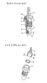
- FIG. 1 is a partially sectional front view of a conventional temperature detection device for detecting a temperature of cooling water of an automobile engine.
- the temperature detection device comprises a metal casing 1 having an opening at an upper end thereof.
- a temperature detection element 2 for example, a temperature-dependent resistor, such as a thermistor, having electrodes 2', 2' on the upper and the lower face thereof, is disposed on an inner face of a casing bottom 1' in the casing 1 at space of a smaller inner diameter.
- a pressure spring 4 presses the temperature detection element 2 to the inner face of the casing bottom 1' through a terminal disk 3, which is disposed between the pressure spring 4 and the temperature detection element 2.
- a rubber packing 6 for attaining moisture-proof and gas-proof ability is disposed on the upper face of a shoulder shaped part at a connecting portion between a smaller inner diameter space in the casing 1 and larger inner diameter space in the casing 1.
- a terminal 7 for taking a detected signal is disposed at the upper open space of the casing 1 so as to make contact to the upper end part of the pressure spring 4.
- An insulation block 8 for holding the terminal 7 is disposed at the inner face of the casing 1 and the outer face of the terminal 7 inbetween and fixed by calking of an upper edge 1" of the casing 1 to the upper end of slots 8' on the outer side of the insulation block 8.
- the temperature detection element 2, the terminal disk 3, the pressure spring 4, the insulation liner 5, the gum packing 6 and the terminal 7 are assembled in the casing 1 in a predetermined manner such that the insulation block 8 between the upper part of the casing 1 and the terminal 7 is fixed by calking of the upper edge 1" of the casing 1 resisting a pressure of the pressure spring 4.
- a temperature is detected by, for instance, immersing the outer bottom of the metal casing in a hot water, thereby conducting the temperature through the bottom 1' to the thermistor 2.
- the terminal 7 is made from a solid brass rod by machine cutting.
- the terminal 7 is molded in the insulation block 8, by means of insert molding. Therefore, because of such machine cutting from a brass rod and subsequent insert molding the manufacturing cost has been expensive.
- slots 8', 8' are formed at surrounding face of the insulation block 8 as shown in FIG. 2, and the upper edge 1" of the metal casing 1 is r calked at respective portions corresponding to the slots 8'.
- a positioning operation to the insulation block finding a right positioning angle is indispensable, and such positioning in the right angle can not be made by a robot insertion machine.
- a temperature detection device of the coventional type is unsuitable for mass production.
- a similar temperature detecting device is known from JP-A-5 343 319.
- This temperature detecting device shows a similar construction and also comprises a metal casing having an opening at an upper end thereof. The lower end of the casing has a space of smaller inner diameter than the opening at the upper end.
- a temperature detection element is disposed on the inner surface of the bottom of the casing together with a terminal disk.
- a pressure spring is disposed between this terminal disk and a solid terminal body at the upper end of the casing. Between the pressure spring and the casing there is arranged an insulating liner and an insulating block is fixed by calking of the upper edge of the casing whereby a packing ring is disposed between the casing and the insulating block.
- a further temperature detecting device is disposed in FR-A-2 450 450.
- This temperature detecting device includes also a metal casing at the inner surface of the bottom of which a temperature detection element is disposed. Further, this temperature detecting device comprises also a pressure spring within the casing and a terminal body at the upper end of the casing. An insulating ring body is mounted within a wider part of the casing and a packing ring is disposed between the insulating ring body and the casing.
- a temperature detecting device is described in the DE-A-23 38 169.
- This temperature detecting device has a rather long metal casing with a small inner diameter at the lower end and a wider inner diameter at the upper end.
- an insulating block which is fixed by flanging of the upper end of the casing.
- an electric conductor Between the temperature detection element at the inner surface of the bottom of the casing and a pressure spring within the insulating block there is disposed an electric conductor and the upper end of the insulating block comprises a terminal of solid material is in contact with the pressure spring.
- the present invention purposes to provide a temperature detection device comprising:
- the temperature detecting device is characterized in that (a1) the upper edge of said further part 902 is formed in a truncated cone shaped calking edge part 903, that (c1) the terminal body is a drawn terminal body 15 wherein the top part 151 is hollow and the base portion is in the form of a hollow truncated cone shaped skirt part 152 connected to said hollow top part 151, said drawn terminal body having a continuous hollow space inside the hollow top part 151 and the skirt part 152, and that (d1) said insulating ring body 16 is disposed on the skirt part 152 of said terminal body 15, the upper peripheral face of said insulating ring body 16 behing held by said truncated cone shaped calking edge part 903.
- a temperature detection device of the present invention has the above-mentioned structure, therefore a material loss could be saved largely and the device could be obtainable at a very low cost.
- angle of the upper face of the insulation ring cap at the part pressed by the calking edge against axis of the terminal cap namely the angle, which is substantially the angle of the outer face of the calking edge part against the axis of the enclosure, is selected in a range of 10° to 60°.
- a positioning operation considering the angular position and a relative spatial position between the insulation ring cap and the calking edge of the enclosure is dispensable, thereby allowing a use of automatic component insertion robot and a sufficient anti-rotation-slip torque between the insulation ring cap and the calking edge of the enclosure is obtainable. Accordingly, a temperature detection device of the present invention is suitable for mass production.
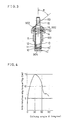
- a metal casing 9 as the enclosure has a slender cup-shaped part 901 defining a slender first space of a smaller inner diameter and a larger depth and a shallow and wider part 902 defining a shallow and wider second space of a larger inner diameter smaller depth and connected to the first space, the upper edge part 903 of the wider part 902 being formed in cone shaped calking edge.
- a temperature detection element 10 of a temperature-dependent resistor, such as a thermistor, having electrodes 10', 10' on the upper and the lower face thereof is disposed on an inner face of a casing bottom 904 in the slender cup shaped part 901 of the casing 9.
- a pressure spring 12 presses the temperature detection element 10 to the inner face of the casing bottom 904 through a terminal disk 11 disposed between the pressure spring 12 and the temperature detection element 10.
- An insulation liner 134 inserted in the metal casing 9 is closely adhered to innerface of the casing 9for insulating inner elements, namely, the temperature detection element 10, the terminal disk 11 and the pressure spring 12 from the metal casing 9.
- a rubber packing 14 for moisture-proof is disposed on the upper face of a shoulder shaped part at a connecting portion between the slender cup-shaped part 901 of the casing 9 and the larger inner diameter part 902 of the casing 9.
- a drawn terminal cap 15 for taking a detected signal is disposed at the upper open end of the casing 9.
- the terminal cap is made of a metal sheet by a drawing process.
- the drawn terminal cap 15 has a slender top part 151 of smaller diameter for serving as a terminal and a cone shaped skirt part 151 connected to the slender top part 151. And further the drawn terminal cap 15 has a continuous hollow space inside the slender top part 151 and the skirt part 152.
- the inner face of the skirt part 152 holds the upper end of the spring 12 and gives pressing force to the spring.
- the upper end of the insulation liner 13 comes in contact to the inner face of the skirt part 152.
- An insulation ring cap 16 having a through hole is disposed on the skirt part 152 of the drawn terminal cap 15 in order to fix the drawn terminal cap 15.
- the insulation ring cap 16 is made of heat-resistive phenol resin, but any other insulating substance having a sufficient mechanical strength can be used.
- the insulation ring cap is fixed by calking with the calking edge part 903 of the metal casing 9 resisting an upward pressure of the pressure spring 12, so that the temperature detection element 10, the terminal disk 11, the compression spring 12, the insulation liner 13 are fixed in the space of the slender part 901 by sealing the space by means of the drawn terminal cap 15, thereby assuring good thermal and electric contact of the temperature detection element to the metal casing 9.
- the primary remarkable advantage of the present invention is that the material loss and manufacturing time can be saved largely and the device could be obtainable at a very low cost by using the drawn terminal cap instead of the conventional solid terminal made from a brass rod worked by machine cutting processing.
- a drawing processing can provide a smooth surface of a product, and therefore a good insertion contact between the drawn terminal cap and the corresponding socket thereof is obtainable. Furthermore, since the drawing work is used to make the terminal cap, a viscous, abrasion resistive and smooth material can be selected for the work material, so that few metal trash exists and therefore a good insulation is obtainable.
- a conventional terminal has been made of brass rod of a material of JIS-C-3601 BD brass which is liable to produce fine metal trash powder when worked and used.
- a drawn terminal cap of the present invention is made of more viscous, abrasion resistive and smooth material of JIS--C-2680R-Q brass, which makes substantially no power trash when worked and used.
- the upper end of the insulation liner 15 is extended into the space of the cone shaped skirt part 152 of the drawn terminal cap 15 exceeding the upper end of the inner face of the cylindrical slender part 901, and accordingly a reliable insulation is secured even if the length of the insulation liner is slightly shorter than designed length as a result of scatter of size since the liner is longer than a necessary length. Since the drawn terminal cap 15 and the insulation ring cap 16 are made as separate components instead of integreal construction by expensive and time taking insert molding processing, further cost saving in manufacturing can be realized.
- the angle of the upper face of the insulation ring cap 16 at the part pressed by calking edge part 903 against axis of the terminal cap 15, namely the angle ⁇ , which is substantially the angle of the outer face of the calking edge part against the axis of the enclosure, is selected in a range of 10° to 60°.
- the inventors made many samples of temperature detecting devices changing the calking angle ⁇ within the range of 0° to 90°, and measured the anti-rotation-slippage torque between the drawn terminal and the casing. The measuring result is shown in FIG. 4.
- the anti-rotation-slippage torque takes a peak value of 15 kg. cm at the calking angle ⁇ is 30°. And the anti-rotation-slippage torque takes smaller value at both the wider or narrower calking angle. 8.
- a required anti-rotation-slippage torque for such temperature detection device for example, for use a cooling water temperature detection unit of an automobile engine, is requested to be more than 10 kg.cm. Therefore, it is recognised from FIG. 4 that the suitable calking angle ⁇ for that required anti-rotation-slippage torque is within 10° to 60°.
Landscapes
- Physics & Mathematics (AREA)
- Nonlinear Science (AREA)
- General Physics & Mathematics (AREA)
- Measuring Temperature Or Quantity Of Heat (AREA)
Claims (3)
Applications Claiming Priority (4)
| Application Number | Priority Date | Filing Date | Title |
|---|---|---|---|
| JP55163646A JPS5786728A (en) | 1980-11-19 | 1980-11-19 | Manufacture of temperature sensor |
| JP166623/80U | 1980-11-19 | ||
| JP163646/80 | 1980-11-19 | ||
| JP16662380U JPS6110191Y2 (fr) | 1980-11-19 | 1980-11-19 |
Publications (3)
| Publication Number | Publication Date |
|---|---|
| EP0052369A2 EP0052369A2 (fr) | 1982-05-26 |
| EP0052369A3 EP0052369A3 (en) | 1982-06-02 |
| EP0052369B1 true EP0052369B1 (fr) | 1986-04-09 |
Family
ID=26489029
Family Applications (1)
| Application Number | Title | Priority Date | Filing Date |
|---|---|---|---|
| EP81109718A Expired EP0052369B1 (fr) | 1980-11-19 | 1981-11-16 | Capteur de température |
Country Status (2)
| Country | Link |
|---|---|
| EP (1) | EP0052369B1 (fr) |
| DE (1) | DE3174346D1 (fr) |
Families Citing this family (3)
| Publication number | Priority date | Publication date | Assignee | Title |
|---|---|---|---|---|
| US5632557A (en) * | 1994-12-16 | 1997-05-27 | Weed Instrument Company, Inc. | Modular temperature sensing apparatus |
| US5667305A (en) * | 1995-06-09 | 1997-09-16 | Ford Motor Company | Low force high pressure port |
| US6488408B1 (en) * | 2000-10-06 | 2002-12-03 | Gecko Electronique, Inc. | Temperature probe mounting device for hot tub spa |
Citations (1)
| Publication number | Priority date | Publication date | Assignee | Title |
|---|---|---|---|---|
| JPS5343319A (en) * | 1976-09-25 | 1978-04-19 | Daimler Benz Ag | Coupler for side controlled motor bus |
Family Cites Families (4)
| Publication number | Priority date | Publication date | Assignee | Title |
|---|---|---|---|---|
| US3748624A (en) * | 1971-03-30 | 1973-07-24 | Nippon Denso Co | Pyrometric sensor using thermistor |
| US3890588A (en) * | 1972-10-26 | 1975-06-17 | Matsushita Electric Industrial Co Ltd | Water jacket temperature sensor |
| DE2338169A1 (de) * | 1973-07-27 | 1975-02-13 | Bosch Gmbh Robert | Elektrischer temperaturfuehler, insbesondere zur messung von abgastemperaturen in kraftfahrzeugen |
| IT7953024U1 (it) * | 1979-02-28 | 1980-08-28 | Borletti Spa | Dispositivo rilevatore di temperatura e/o indicatore del raggiungimento di un valore prefissato di temperatura in un liquido |
-
1981
- 1981-11-16 DE DE8181109718T patent/DE3174346D1/de not_active Expired
- 1981-11-16 EP EP81109718A patent/EP0052369B1/fr not_active Expired
Patent Citations (1)
| Publication number | Priority date | Publication date | Assignee | Title |
|---|---|---|---|---|
| JPS5343319A (en) * | 1976-09-25 | 1978-04-19 | Daimler Benz Ag | Coupler for side controlled motor bus |
Also Published As
| Publication number | Publication date |
|---|---|
| DE3174346D1 (en) | 1986-05-15 |
| EP0052369A3 (en) | 1982-06-02 |
| EP0052369A2 (fr) | 1982-05-26 |
Similar Documents
| Publication | Publication Date | Title |
|---|---|---|
| EP1519173B1 (fr) | Capteur de force a semi-conducteur | |
| US4276532A (en) | Thermal fuse | |
| US4145588A (en) | Condition responsive apparatus having freely disposed disc | |
| JP2519560B2 (ja) | 感熱スイッチ | |
| US4296287A (en) | Weatherproofed condition responsive switch | |
| US4548780A (en) | Sensing devices for mounting in chamber walls and a method of manufacture | |
| US4636598A (en) | Pressure switch with non-conductive housing and axially spaced terminals | |
| EP0052369B1 (fr) | Capteur de température | |
| US4469923A (en) | Pressure responsive switch with discrete pressure responsive unit | |
| US4109229A (en) | Thermally actuatable electrical switch subassembly thereof | |
| US7640812B2 (en) | Flexible board sensor and manufacturing method of sensor | |
| US5483216A (en) | Fixing assembly of a temperature responsive element and its fixing method | |
| US4075596A (en) | Sealed casing for a thermally actuable electrical switch | |
| US4532390A (en) | Diaphragm pressure switch for controlling small pressure gradients | |
| US4887063A (en) | Insulating casing for thermal switches | |
| US4083332A (en) | Fitting of a fluid temperature switch in a wall | |
| US4260862A (en) | Condition responsive apparatus having an improved motion transfer member | |
| EP0769794B1 (fr) | Dispositif de protection pour composant électrique | |
| US5519179A (en) | Pressure switch | |
| CN216449048U (zh) | 带温度保险丝的温度传感器 | |
| GB2165697A (en) | Thermal switching device | |
| US4514717A (en) | Single terminal snap acting thermal switch | |
| US4317100A (en) | Readily mountable thermostat | |
| JPS6025794Y2 (ja) | 温度ヒユ−ズ | |
| US4197634A (en) | Method of making a thermally actuatable electrical switch construction |
Legal Events
| Date | Code | Title | Description |
|---|---|---|---|
| PUAI | Public reference made under article 153(3) epc to a published international application that has entered the european phase |
Free format text: ORIGINAL CODE: 0009012 |
|
| PUAL | Search report despatched |
Free format text: ORIGINAL CODE: 0009013 |
|
| AK | Designated contracting states |
Designated state(s): DE FR GB |
|
| AK | Designated contracting states |
Designated state(s): DE FR GB |
|
| 17P | Request for examination filed |
Effective date: 19821116 |
|
| GRAA | (expected) grant |
Free format text: ORIGINAL CODE: 0009210 |
|
| AK | Designated contracting states |
Kind code of ref document: B1 Designated state(s): DE FR GB |
|
| REF | Corresponds to: |
Ref document number: 3174346 Country of ref document: DE Date of ref document: 19860515 |
|
| ET | Fr: translation filed | ||
| PLBE | No opposition filed within time limit |
Free format text: ORIGINAL CODE: 0009261 |
|
| STAA | Information on the status of an ep patent application or granted ep patent |
Free format text: STATUS: NO OPPOSITION FILED WITHIN TIME LIMIT |
|
| 26N | No opposition filed | ||
| PGFP | Annual fee paid to national office [announced via postgrant information from national office to epo] |
Ref country code: GB Payment date: 19941108 Year of fee payment: 14 |
|
| PGFP | Annual fee paid to national office [announced via postgrant information from national office to epo] |
Ref country code: FR Payment date: 19941109 Year of fee payment: 14 |
|
| PGFP | Annual fee paid to national office [announced via postgrant information from national office to epo] |
Ref country code: DE Payment date: 19941110 Year of fee payment: 14 |
|
| PG25 | Lapsed in a contracting state [announced via postgrant information from national office to epo] |
Ref country code: GB Effective date: 19951116 |
|
| GBPC | Gb: european patent ceased through non-payment of renewal fee |
Effective date: 19951116 |
|
| PG25 | Lapsed in a contracting state [announced via postgrant information from national office to epo] |
Ref country code: FR Effective date: 19960731 |
|
| PG25 | Lapsed in a contracting state [announced via postgrant information from national office to epo] |
Ref country code: DE Effective date: 19960801 |
|
| REG | Reference to a national code |
Ref country code: FR Ref legal event code: ST |