EP0052372A1 - Sattelgehäuse einer Scheibenbremse - Google Patents
Sattelgehäuse einer Scheibenbremse Download PDFInfo
- Publication number
- EP0052372A1 EP0052372A1 EP81109721A EP81109721A EP0052372A1 EP 0052372 A1 EP0052372 A1 EP 0052372A1 EP 81109721 A EP81109721 A EP 81109721A EP 81109721 A EP81109721 A EP 81109721A EP 0052372 A1 EP0052372 A1 EP 0052372A1
- Authority
- EP
- European Patent Office
- Prior art keywords
- caliper
- connecting portion
- end wall
- rotor
- reaction
- Prior art date
- Legal status (The legal status is an assumption and is not a legal conclusion. Google has not performed a legal analysis and makes no representation as to the accuracy of the status listed.)
- Granted
Links
- 230000001965 increasing effect Effects 0.000 claims description 11
- 230000003247 decreasing effect Effects 0.000 claims description 2
- 230000002787 reinforcement Effects 0.000 abstract description 5
- 210000003414 extremity Anatomy 0.000 description 5
- 230000000712 assembly Effects 0.000 description 4
- 238000000429 assembly Methods 0.000 description 4
- 239000012530 fluid Substances 0.000 description 4
- 230000000694 effects Effects 0.000 description 2
- 238000012423 maintenance Methods 0.000 description 2
- 238000012986 modification Methods 0.000 description 2
- 230000004048 modification Effects 0.000 description 2
- 210000001364 upper extremity Anatomy 0.000 description 2
- 230000015572 biosynthetic process Effects 0.000 description 1
- 230000007423 decrease Effects 0.000 description 1
- 230000002708 enhancing effect Effects 0.000 description 1
- 238000007689 inspection Methods 0.000 description 1
- 238000004519 manufacturing process Methods 0.000 description 1
- 230000000717 retained effect Effects 0.000 description 1
- 238000000926 separation method Methods 0.000 description 1
- 238000009423 ventilation Methods 0.000 description 1
Images

Classifications
-
- F—MECHANICAL ENGINEERING; LIGHTING; HEATING; WEAPONS; BLASTING
- F16—ENGINEERING ELEMENTS AND UNITS; GENERAL MEASURES FOR PRODUCING AND MAINTAINING EFFECTIVE FUNCTIONING OF MACHINES OR INSTALLATIONS; THERMAL INSULATION IN GENERAL
- F16D—COUPLINGS FOR TRANSMITTING ROTATION; CLUTCHES; BRAKES
- F16D55/00—Brakes with substantially-radial braking surfaces pressed together in axial direction, e.g. disc brakes
- F16D55/02—Brakes with substantially-radial braking surfaces pressed together in axial direction, e.g. disc brakes with axially-movable discs or pads pressed against axially-located rotating members
- F16D55/22—Brakes with substantially-radial braking surfaces pressed together in axial direction, e.g. disc brakes with axially-movable discs or pads pressed against axially-located rotating members by clamping an axially-located rotating disc between movable braking members, e.g. movable brake discs or brake pads
- F16D55/224—Brakes with substantially-radial braking surfaces pressed together in axial direction, e.g. disc brakes with axially-movable discs or pads pressed against axially-located rotating members by clamping an axially-located rotating disc between movable braking members, e.g. movable brake discs or brake pads with a common actuating member for the braking members
- F16D55/225—Brakes with substantially-radial braking surfaces pressed together in axial direction, e.g. disc brakes with axially-movable discs or pads pressed against axially-located rotating members by clamping an axially-located rotating disc between movable braking members, e.g. movable brake discs or brake pads with a common actuating member for the braking members the braking members being brake pads
- F16D55/226—Brakes with substantially-radial braking surfaces pressed together in axial direction, e.g. disc brakes with axially-movable discs or pads pressed against axially-located rotating members by clamping an axially-located rotating disc between movable braking members, e.g. movable brake discs or brake pads with a common actuating member for the braking members the braking members being brake pads in which the common actuating member is moved axially, e.g. floating caliper disc brakes
- F16D55/2265—Brakes with substantially-radial braking surfaces pressed together in axial direction, e.g. disc brakes with axially-movable discs or pads pressed against axially-located rotating members by clamping an axially-located rotating disc between movable braking members, e.g. movable brake discs or brake pads with a common actuating member for the braking members the braking members being brake pads in which the common actuating member is moved axially, e.g. floating caliper disc brakes the axial movement being guided by one or more pins engaging bores in the brake support or the brake housing
- F16D55/227—Brakes with substantially-radial braking surfaces pressed together in axial direction, e.g. disc brakes with axially-movable discs or pads pressed against axially-located rotating members by clamping an axially-located rotating disc between movable braking members, e.g. movable brake discs or brake pads with a common actuating member for the braking members the braking members being brake pads in which the common actuating member is moved axially, e.g. floating caliper disc brakes the axial movement being guided by one or more pins engaging bores in the brake support or the brake housing by two or more pins
-
- F—MECHANICAL ENGINEERING; LIGHTING; HEATING; WEAPONS; BLASTING
- F16—ENGINEERING ELEMENTS AND UNITS; GENERAL MEASURES FOR PRODUCING AND MAINTAINING EFFECTIVE FUNCTIONING OF MACHINES OR INSTALLATIONS; THERMAL INSULATION IN GENERAL
- F16D—COUPLINGS FOR TRANSMITTING ROTATION; CLUTCHES; BRAKES
- F16D55/00—Brakes with substantially-radial braking surfaces pressed together in axial direction, e.g. disc brakes
- F16D2055/0004—Parts or details of disc brakes
- F16D2055/0016—Brake calipers
Definitions
- the present invention relates to an improved caliper used in a disc braking system and more particularly, to improvements in structural configuration of the caliper housing for increased performance and service life of the braking system..
- a generally U-shaped caliper or caliper housing for use in a disc brake system comprises: a brake actuating hydraulic cylinder portion wherein a fluid-actuated piston is slidably received; a reaction portion which is positioned opposite to the cylinder portion axially of a disc rotor rotating with a vehicle wheel, so that it.s.andwiches, in combination with the opposing cylinder portion, the disc rotor and brake pad assemblies disposed in parallel to, and on opposite sides of, the disc rotor; and a connecting portion which extends transversely or along the axis of the disc rotor over the periphery of the rotor and terminates in the reaction portion, thus connecting the cylinder and reaction portions to constitute an integral caliper housing.
- the caliper is supported by a fixed member of the vehicle in such manner that the former is movable axially of the disc rotor. It is noted in the pertinent art that the maximum permissible diameter of the disc rotor is limited by a specific wall thickness of the connecting portion of the caliper . Because the disc rotor and the caliper which straddles the rotor are disposed in a relatively limited space formed inside the rim of the vehicle wheel. Thus, it has been a long-felt but unsolved need to maximize the diameter of the disc rotor for enhancing the braking performance of a vehicle and more particularly, to thereby increase the operating area of the brake pads for prolonging the required time interval of maintenance of the braking system.
- the connecting portion of a disc brake caliper must have a wall thickness more than a certain lower limit (approximately 20mm) in order to ensure a rigidity enough to avoid the tendency of axially outward deflection of the opposing cylinder and reaction portions or separation thereof away from each other in opposite directions along the axis of the rotor when the piston in the cylinder portion is actuated by pressurized fluid upon brake application.
- a certain lower limit approximately 20mm
- the inventors of the present invention through continuing and scrupulous research efforts and trial manufacturing activities on a number of calipers of different configurations which were made in view of the above situations in the art, found a surprising fact that the thickness of the connecting portion of the caliper housing can be reduced without the sacrifice of decreasing its rigidity by means of so forming the reaction portion as to include an end wall which extends radially inwardly of the disc rotor from the extremity of the connecting portion.
- This invention was made based on the above knowledge and discovery.
- a caliper for a vehicle disc brake including a hydraulic cylinder portion within which a piston is slidably received, an reaction portion located in confrontation with the hydraulic cylinder portion, and a connecting portion connecting the hydraulic cylinder and reaction portions at upper ends thereof, the caliper being adapted to be supported by a non-rotatable member of a vehicle so that it is freely movable along the axis of a disc rotor, the caliper being characterized in that the connecting portion has a cross section, taken perpendicularly to the axis of the cylinder portion, which is of substantially circular arc configuration concentric to the disc rotor, and further characterized in that the reaction portion is formed of an arcuate end wall extending radially inwardly of the circular arc from the entire length of extremity of the connecting portion, and of a pair of j.aw portions further extending radially inwardly from the end wall.
- an improved caliper thus constructed according to this invention maintains a high level of rigidity enough to prevent possible deflection thereof otherwise occurring when its connecting portion has a reduced wall thickness.
- This high rigidity of the caliper is attributed to the formation of an integral reinforcement housing structure or shell structure which is constituted by the connecting portion and the end wall of the reaction portion, as distinguished from conventional types of calipers which generally owe their deflection resisting rigidity to maintenance of a relatively large wall thickness of their connecting portion.
- the present invention provides a caliper housing for a disc brake which has a reduced wall thickness but maintains the required rigidity.
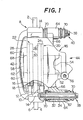
- a disc brake of pin-sliding caliper type which includes a disc rotor 2 having friction surfaces 4 and 6 on both sides thereof and rotating about its axis together with an axle of a vehicle not shown. Adjacent to the disc rotor 2 is disposed a non-rotatable torque member 8 in such manner as to straddle the rotor 2.
- the torque member 8 which is fixed to the knucle, axle housing or other member of the vehicle, includes planar portions 10 and 12 extending along the friction surfaces 4 and 6 of the disc rotor 2 and a connecting portion 14 which is bridged between the planar portions 10 and 12 axially of the disc rotor 2 and over the periphery thereof to connect the portions 10 and 12.
- openings 16 and 18 In the central parts of the planar portions 10 and 12, there are formed openings 16 and 18, respectively, within which are movably received an inner and an outer pad assemblies 20 and 22, respectively, with. one face thereof facing the respective friction surfaces 4, 6 of the rotor 2.
- the inner pad assembly 20 consists of a backing plate 24 and a friction member 28, and the outer pad assembly 22 of a backing plate 26 and a friction member 30.
- Each of the pins 38 and 40 includes a sleeve 32 and a bolt 34, 36 inserted therethrough to retain the sleeve 32.
- a caliper 44 which comprises a hydraulic pressure cylinder portion 46, a reaction portion 48 facing the cylinder portion 46 axially of the disc rotor 2, and a connecting portion 50 extending axially between the cylinder and reaction portions 46 and 48 to connect them at their upper ends as seen in Fig. 3.
- These three portions 46, 48 and 50 constitute an integral caliper housing structure of virtually saddle-like configuration which straddles the disc rotor 2 and the pad assemblies 20 and 22 disposed on both sides of, and in parallel to, the disc rotor 2.
- the cylinder portion 46 has, in a part thereof facing the inner pad assembly 20, a cylinder bore 52 within which a piston 54 is slidably received in a fluid-tight manner.
- Numeral 56 designates a fluid inlet port communicating with the inner chamber of the cylinder bore 52.
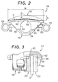
- the connecting portion 50 extends from the upper extremity of the cylinder portion 46 as seen in Fig. 3, forming a substantially circular arc configuration, concentric to the disc rotor 2, in cross section taken along the sides of the disc rotor, i.e., perpendicularly to the axis of the cylinder portion 46 as seen in Fig. 2.
- the reaction portion 48 includes an arcuate or crescent-shaped end wall 58 facing the cylinder portion 46 and extending radially inwardly of the disc rotor 2 from the entire length of the extremity of the-connecting portion 50 which is opposite to the extremity of the same terminating in the said upper extremity of the cylinder portion 46, and further includes a pair of jaw portions 60 which are spaced from each other circumferentially of the disc rotor 2 and extended radially inwardly further from the end wall 58.
- the pair of jaw portions 60 are so formed that their thickness decreases from the base toward the tip.
- the end wall 58 is provided, at its radially inward end portion, with a rib 62 which protrudes in the axial direction away from the cylinder portion 46 as seen in Fig.
- W/T is preferable to be in the invented caliper not less than 11 against the traditional value 4-9, in particular preferable to be in the range of 12-20;
- D/T is preferable to be not less than 1.3 against the traditional value 0.3-0.7, particular desirable range is 1.5-2.5;
- L/T is preferable to be not less than 1.4 against the traditional value of 1 or less, and a particularly recommendable range of the value is 1.5-2.5.
- a pair of radially spaced arms 66 as seen in Fig. 1, each of which includes at its end a bored boss 64 through which the pin 38, 40 is inserted via a collar 67, whereby the caliper 44 is supported freely movably axially of the disc rotor 2.
- the pins 38 and 40 are provided at their exposed portions with dust- tight boots 70.
- the connecting portion 50 of the caliper 44 of this embodiment which is of circular are configuration in cross section, is protected against such downward deflection by virtue of the structure of the reaction portion 48 which is characterized by the arcuate or crescent-shaped end wall 58 extending radially inwardly from the extremity of the connecting portion 50 as well as by the pair of jaw portions 60, an inverted-U-shaped opening 68 being defined therebetween such that the extreme bottom is located at a point radially inwardly away from the connecting portion 50.
- the end wall 58 and the connecting portion 50 constitute a reinforcement frame structure which ensures a high level of rigidity for preventing the cylinder and reaction portions 46 and 48 from separating from each other axially of the disc rotor 2.
- the connecting portion 50 may have a reduced thickness as compared to that of the similar portion of the conventional calipers. According to the experimentation carried out by the inventors, the thickness may be reduced to about a half (approximately 10mm) that of the conventional ' calipers. This means, it is possible to use a disc rotor which has an increased diameter in proportion to the obtained reduction in wall thickness of the connecting portion 50.
- the invention may also apply to other types of disc brake as long as they use a caliper straddling the disc rotor.
- the end wall 58 which was in the above embodiment provided with the rib 62 for increasing the rigidity, has been altered by doing away the rib 62 to be progressively increased in the thickness thereof toward its central part in respect of the circumferential direction of the disc rotor 2 for attaining the same effect obtained by the rib 62.
- Such an end wall 70 is illustrated in Figs. 4 and 5.
- the connecting portion 71 may have an opening 72 or openings therethrough for ventilation or inspection to the extent that such openings do not reduce the rigidity of the reinforcement frame structure previously indicated.
- connecting portion 50 an increased length of arc defining the cross sectional circular arc configuration for the purpose of increasing the rigidity of the reinforcement frame structure.
Landscapes
- Engineering & Computer Science (AREA)
- General Engineering & Computer Science (AREA)
- Mechanical Engineering (AREA)
- Braking Arrangements (AREA)
Applications Claiming Priority (2)
| Application Number | Priority Date | Filing Date | Title |
|---|---|---|---|
| JP164859/80 | 1980-11-18 | ||
| JP1980164859U JPS6344587Y2 (de) | 1980-11-18 | 1980-11-18 |
Publications (2)
| Publication Number | Publication Date |
|---|---|
| EP0052372A1 true EP0052372A1 (de) | 1982-05-26 |
| EP0052372B1 EP0052372B1 (de) | 1986-05-14 |
Family
ID=15801267
Family Applications (1)
| Application Number | Title | Priority Date | Filing Date |
|---|---|---|---|
| EP81109721A Expired EP0052372B1 (de) | 1980-11-18 | 1981-11-16 | Sattelgehäuse einer Scheibenbremse |
Country Status (3)
| Country | Link |
|---|---|
| EP (1) | EP0052372B1 (de) |
| JP (1) | JPS6344587Y2 (de) |
| DE (1) | DE3174645D1 (de) |
Cited By (3)
| Publication number | Priority date | Publication date | Assignee | Title |
|---|---|---|---|---|
| DE3508039A1 (de) * | 1984-07-26 | 1986-01-30 | Alfred Teves Gmbh, 6000 Frankfurt | Innen umgriffene scheibenbremse, insbesondere fuer kraftfahrzeuge |
| FR2580754A1 (fr) * | 1985-04-22 | 1986-10-24 | Teves Gmbh Alfred | Capuchon de protection pour une broche de guidage d'etrier de frein a disque |
| US4854423A (en) * | 1988-07-26 | 1989-08-08 | Kelsey Hayes Company | Hydraulic disc brake drum-in-hat parking brake assembly |
Citations (8)
| Publication number | Priority date | Publication date | Assignee | Title |
|---|---|---|---|---|
| GB1054224A (de) * | 1964-12-17 | |||
| FR1340290A (fr) * | 1962-09-05 | 1963-10-18 | Ardennaise D Essieux Soc | Frein à disque |
| GB1194435A (en) * | 1967-09-15 | 1970-06-10 | Teves Gmbh Alfred | Improvements in or relating to Disc Brakes |
| US3548973A (en) * | 1967-11-15 | 1970-12-22 | Dba Sa | Stirrup for disc brake |
| GB1355960A (en) * | 1971-03-08 | 1974-06-12 | Automotive Prod Co Ltd | Disc brakes |
| GB2016617A (en) * | 1978-03-01 | 1979-09-26 | Girling Ltd | Disc brake |
| GB2018920A (en) * | 1978-04-17 | 1979-10-24 | Teves Gmbh Alfred | Floating caliper disc brake |
| GB2042659A (en) * | 1979-02-03 | 1980-09-24 | Teves Gmbh Alfred | Disc brake |
Family Cites Families (3)
| Publication number | Priority date | Publication date | Assignee | Title |
|---|---|---|---|---|
| FR2344751A1 (fr) * | 1976-03-16 | 1977-10-14 | Dba | Frein a disque et ecran thermique pour un tel frein |
| GB1575513A (en) * | 1976-04-01 | 1980-09-24 | Girling Ltd | Disc brake calipers |
| FR2456259A1 (fr) * | 1979-05-07 | 1980-12-05 | Citroen Sa | Perfectionnements aux freins a disque |
-
1980
- 1980-11-18 JP JP1980164859U patent/JPS6344587Y2/ja not_active Expired
-
1981
- 1981-11-16 DE DE8181109721T patent/DE3174645D1/de not_active Expired
- 1981-11-16 EP EP81109721A patent/EP0052372B1/de not_active Expired
Patent Citations (8)
| Publication number | Priority date | Publication date | Assignee | Title |
|---|---|---|---|---|
| FR1340290A (fr) * | 1962-09-05 | 1963-10-18 | Ardennaise D Essieux Soc | Frein à disque |
| GB1054224A (de) * | 1964-12-17 | |||
| GB1194435A (en) * | 1967-09-15 | 1970-06-10 | Teves Gmbh Alfred | Improvements in or relating to Disc Brakes |
| US3548973A (en) * | 1967-11-15 | 1970-12-22 | Dba Sa | Stirrup for disc brake |
| GB1355960A (en) * | 1971-03-08 | 1974-06-12 | Automotive Prod Co Ltd | Disc brakes |
| GB2016617A (en) * | 1978-03-01 | 1979-09-26 | Girling Ltd | Disc brake |
| GB2018920A (en) * | 1978-04-17 | 1979-10-24 | Teves Gmbh Alfred | Floating caliper disc brake |
| GB2042659A (en) * | 1979-02-03 | 1980-09-24 | Teves Gmbh Alfred | Disc brake |
Cited By (3)
| Publication number | Priority date | Publication date | Assignee | Title |
|---|---|---|---|---|
| DE3508039A1 (de) * | 1984-07-26 | 1986-01-30 | Alfred Teves Gmbh, 6000 Frankfurt | Innen umgriffene scheibenbremse, insbesondere fuer kraftfahrzeuge |
| FR2580754A1 (fr) * | 1985-04-22 | 1986-10-24 | Teves Gmbh Alfred | Capuchon de protection pour une broche de guidage d'etrier de frein a disque |
| US4854423A (en) * | 1988-07-26 | 1989-08-08 | Kelsey Hayes Company | Hydraulic disc brake drum-in-hat parking brake assembly |
Also Published As
| Publication number | Publication date |
|---|---|
| EP0052372B1 (de) | 1986-05-14 |
| JPS6344587Y2 (de) | 1988-11-18 |
| JPS5787836U (de) | 1982-05-31 |
| DE3174645D1 (en) | 1986-06-19 |
Similar Documents
| Publication | Publication Date | Title |
|---|---|---|
| US5706917A (en) | Disc brake having a shim engaged between a piston and a friction pad for retracting the friction pad upon retraction of the piston | |
| US6257379B1 (en) | Disk brake | |
| US4458790A (en) | Caliper mounting suspension | |
| JP7753494B2 (ja) | 車両用ディスクブレーキ | |
| US4130186A (en) | Ribbed brake shoe support plate for cylindrical ring type brake | |
| US4350229A (en) | Disc brake having a slidably supported caliper | |
| US4613018A (en) | Braking caliper for a spot-type disc brake | |
| US4603761A (en) | Floating caliper type disc brake | |
| US2894607A (en) | Disc brakes | |
| GB2085101A (en) | Light weight disc brake caliper | |
| EP0096553B1 (de) | Scheibenzusammensetzungen für Bremsen | |
| CA1222959A (en) | Caliper for a disc brake and a method for manufacturing the same | |
| EP0560146A2 (de) | Scheibenbremsvorrichtung | |
| EP0052372A1 (de) | Sattelgehäuse einer Scheibenbremse | |
| CN111094783B (zh) | 对置活塞型盘式制动器用卡钳 | |
| US4448287A (en) | Caliper housing in a disc brake | |
| US3951239A (en) | Plural disc brake systems | |
| GB2160600A (en) | Disc brake | |
| AU594729B2 (en) | Disk brake of the guide pin type | |
| US6983830B2 (en) | Disc brake | |
| GB1572744A (en) | Fluid-pressure-operated brakes for vehicles | |
| IT8222718A1 (it) | PERFEZIONAMENTI AI FRENI A DISCo | |
| US4039054A (en) | Disc brakes for vehicles | |
| GB2061428A (en) | Friction pad assemblies for vehicle disc brakes | |
| JP4718422B2 (ja) | ディスクブレーキ |
Legal Events
| Date | Code | Title | Description |
|---|---|---|---|
| PUAI | Public reference made under article 153(3) epc to a published international application that has entered the european phase |
Free format text: ORIGINAL CODE: 0009012 |
|
| AK | Designated contracting states |
Designated state(s): DE FR GB |
|
| 17P | Request for examination filed |
Effective date: 19821028 |
|
| RAP1 | Party data changed (applicant data changed or rights of an application transferred) |
Owner name: AISIN SEIKI KABUSHIKI KAISHA Owner name: TOYOTA JIDOSHA KOGYO KABUSHIKI KAISHA |
|
| RAP1 | Party data changed (applicant data changed or rights of an application transferred) |
Owner name: AISIN SEIKI KABUSHIKI KAISHA Owner name: TOYOTA JIDOSHA KABUSHIKI KAISHA |
|
| GRAA | (expected) grant |
Free format text: ORIGINAL CODE: 0009210 |
|
| AK | Designated contracting states |
Kind code of ref document: B1 Designated state(s): DE FR GB |
|
| REF | Corresponds to: |
Ref document number: 3174645 Country of ref document: DE Date of ref document: 19860619 |
|
| ET | Fr: translation filed | ||
| PLBE | No opposition filed within time limit |
Free format text: ORIGINAL CODE: 0009261 |
|
| STAA | Information on the status of an ep patent application or granted ep patent |
Free format text: STATUS: NO OPPOSITION FILED WITHIN TIME LIMIT |
|
| 26N | No opposition filed | ||
| PGFP | Annual fee paid to national office [announced via postgrant information from national office to epo] |
Ref country code: GB Payment date: 19911106 Year of fee payment: 11 |
|
| PGFP | Annual fee paid to national office [announced via postgrant information from national office to epo] |
Ref country code: FR Payment date: 19911107 Year of fee payment: 11 |
|
| PGFP | Annual fee paid to national office [announced via postgrant information from national office to epo] |
Ref country code: DE Payment date: 19911230 Year of fee payment: 11 |
|
| PG25 | Lapsed in a contracting state [announced via postgrant information from national office to epo] |
Ref country code: GB Effective date: 19921116 |
|
| GBPC | Gb: european patent ceased through non-payment of renewal fee |
Effective date: 19921116 |
|
| PG25 | Lapsed in a contracting state [announced via postgrant information from national office to epo] |
Ref country code: FR Effective date: 19930730 |
|
| PG25 | Lapsed in a contracting state [announced via postgrant information from national office to epo] |
Ref country code: DE Effective date: 19930803 |
|
| REG | Reference to a national code |
Ref country code: FR Ref legal event code: ST |