EP0052386B1 - Dispositif à grande capacité pour amener des objets cylindriques vers une machine pour l'impression sérigraphique - Google Patents
Dispositif à grande capacité pour amener des objets cylindriques vers une machine pour l'impression sérigraphique Download PDFInfo
- Publication number
- EP0052386B1 EP0052386B1 EP81201080A EP81201080A EP0052386B1 EP 0052386 B1 EP0052386 B1 EP 0052386B1 EP 81201080 A EP81201080 A EP 81201080A EP 81201080 A EP81201080 A EP 81201080A EP 0052386 B1 EP0052386 B1 EP 0052386B1
- Authority
- EP
- European Patent Office
- Prior art keywords
- shaft
- objects
- shafts
- lever
- swinging
- Prior art date
- Legal status (The legal status is an assumption and is not a legal conclusion. Google has not performed a legal analysis and makes no representation as to the accuracy of the status listed.)
- Expired
Links
- 238000007650 screen-printing Methods 0.000 title claims abstract description 7
- 238000007639 printing Methods 0.000 claims abstract description 21
- 238000011144 upstream manufacturing Methods 0.000 description 6
- 238000004519 manufacturing process Methods 0.000 description 3
- 241000252254 Catostomidae Species 0.000 description 2
- 239000006096 absorbing agent Substances 0.000 description 1
- 238000010276 construction Methods 0.000 description 1
- 238000000151 deposition Methods 0.000 description 1
- 238000006073 displacement reaction Methods 0.000 description 1
- 238000010438 heat treatment Methods 0.000 description 1
- 230000002035 prolonged effect Effects 0.000 description 1
- 230000000717 retained effect Effects 0.000 description 1
- 230000000630 rising effect Effects 0.000 description 1
- 230000035939 shock Effects 0.000 description 1
- 229920002994 synthetic fiber Polymers 0.000 description 1
Images




Classifications
-
- B—PERFORMING OPERATIONS; TRANSPORTING
- B41—PRINTING; LINING MACHINES; TYPEWRITERS; STAMPS
- B41F—PRINTING MACHINES OR PRESSES
- B41F15/00—Screen printers
- B41F15/08—Machines
- B41F15/0872—Machines for printing on articles having essentially cylindrical surfaces
Definitions
- Silk-screen printing machines for printing on to objects for example cylindrical objects, are known to have a particularly high production capacity.
- the object transfer speed is doubled without increasing the operating rate or frequency of the moving members.
- the objects are loaded on to the device according to the invention by a machine of known type, not shown.
- the printing machine 2 comprises a normal screen support carriage 4 disposed above a normal screen 5 ( Figure 2).
- a horizontal transverse pin 14 is rotatably mounted on the lower part of the frame 1, and from its opposing ends there branch two arms 15 and 16, substantially perpendicular to each other.
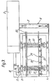
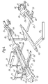
- a shaft entirely similar to the shaft 22 heretofore described is rotatably mounted on the downstream end part of the frame 1, as is apparent from Figures 1, 3 and 4.
- the distance between the two longitudinal elements 25 can be adjusted according to the length of the objects 3 by means of an adjustment bar 26 which connects together the two sleeves by which the front longitudinal element 25 is mounted on said two right hand bars 24.
- each individual mounting sleeve the corresponding free end of the adjustment bar 26 is prvided with a toothed wheel which is in constant engagement with toothing 27 on the relative right hand cylindrical bar 24.
- a toothed wheel which is in constant engagement with toothing 27 on the relative right hand cylindrical bar 24.
- two vertical longitudinal plates 28 which can be adjusted in level relative to their own longitudinal support elements 25 by means of suitable threaded columns.
- each individual plate 28 comprises a set of equidistantly spaced notches or seats 29 for receiving the corresponding ends of the objects 3.
- the two cylindrical bars 24 which in Figure 4 are located to the left of the corresponding shafts 22 are connected together at their rear by a backing plate 30 which is disposed parallel to and on the outer side of the rear plate 28.
- Each arm 34 is upperly provided with a counter-point 35, which is mounted on a resilient support.
- the rear end of the drive shaft 9 carries, keyed thereon, a conveniently profiled cam 37, the contour which is constantly contacted by an idle roller 38 centrally mounted on a lever 39, the opposing ends of which are hinged to the frame 1 and to a connecting rod 40 respectively.
- connecting rod 40 Practically parallel to the connecting rod 40 there is provided a further connecting rod 42, of which the lower end is hinged to the frame 1 and the upper end is hinged to the triangular plate 41 where the connecting rod 44 is pivoted.
- a double gripper 56 On the keying shaft of the last gear of the first gear train 55 there is keyed a double gripper 56, with pairs of jaws which are diametrically opposed about said shaft, and which is controlled by means of a small double acting pneumatic cylinder-piston unit, not shown.
- the rear toothed wheel 54 is engaged by the toothed sector 59, the keying shaft 68 of which is located on that side of the axis of rotation of the cross 53 opposite that occupied by the common shaft of the two gear wheels 54.
- the shaft 68 is suspended from the common shaft of the gear wheels 54, two further connecting rods 61 hinged to the frame 1 also being connected to said shaft 68.
- the lower end of the rocker arm 64 is operated by a suitably profiled cam 65, which is keyed on to a shaft 900 controlled by the drive shaft 9.
- the invention heretofore described is able to feed a large number of cylindrical objects 3 to a silk-screen printing machine 2 in a given time unit.
- the invention is provided, in the transverse downstream zone of the elements 30, 31 and 28 in which the suckers 58 are located when in their lowered position, with a normal positioning or locating device which has not been shown for clarity and simplicity of drawing.
- the two hinging points of the connecting rod 83 are constituted by two convenient ball joints.
- a suitable chain winds around the two toothed wheels 75, and passes over a ring gear 76 keyed on a rotatable shaft, this latter mounted on the support 80.
- the rear end of said rotatable shaft has keyed thereon a toothed wheel 74 which engages with a ring gear sector 73 with internal toothing, which is supported by the frame 1 ( Figures 2 and 9).
- the motion for rotating the breech member of said positioning unit is derived from a further toothed wheel 760 which is keyed on to said rotatable shaft, as shown in Figure 9.
- Three rotatable or idle counter-points 350 are disposed on the shaft 31 between said set of counter-points 35, and in a position corresponding with the breech members 79 and the breech member of said positioning unit.
- the backing plate 30 is provided with convenient apertures to enable the base of said breech members to pass slightly beyond the active face of the backing plate 30.
- the drive unit of the printing machine 2 rotates the drive shaft 9, which by way of the elements 8, 7, 6 and 10, drives the screen support carriage 4 ( Figure 2).
- the working head 11 is also operated in known manner ( Figure 3).
- an object 3 which in this case is constituted by a small bottle, is loaded by a normal loading unit into the first of the two free notches or seats 29 in the plates 28.
- the counter-points 35 and 350 are perfectly aligned with the objects 3 supported by the plates 28, and when said shafts 22 reverse their direction of rotation, the shafts 31 and 81 are swung inwards by the connecting rods 48 and 83, these latter being controlled by the pantograph device.
- the shafts 22 begin to rotate in a right hand direction, so that the elements 30 and 31 and the plates 28 move in the opposite direction to that described heretofore.
- each object is raised from the two seats 29 which it previously occupied, and at the end of said right hand rotation is deposited into the two immediately downstream seats 29 because the shafts 31 and 81 again swing outwards.
- the elements 30, 31 and the plates 28 are subjected to two opposite reciprocating movements over circumferential arc paths, so as to define an overall movement of the hand-to-hand type.
- the transfer motion of the flame treatment or heating heads follows the two underlying objects which are heated over their entire outer surface as they are rotated by the elements 73, 74, 76, 75, 77 and 79.
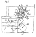
- the toothed sector 59 is also rotated by the cam 65 as can be better seen in Figures 5 and 6, so that the double gripper 56 and double sucker 58 rotate substantially through 180° relative to the cross.
Landscapes
- Engineering & Computer Science (AREA)
- Mechanical Engineering (AREA)
- Feeding Of Articles By Means Other Than Belts Or Rollers (AREA)
- Screen Printers (AREA)
- Manufacturing Of Printed Wiring (AREA)
- Treatment Of Fiber Materials (AREA)
- Specific Conveyance Elements (AREA)
Claims (7)
Priority Applications (1)
| Application Number | Priority Date | Filing Date | Title |
|---|---|---|---|
| AT81201080T ATE10604T1 (de) | 1980-11-14 | 1981-09-29 | Hochleistungsvorrichtung zum zufuehren von zylindrischen gegenstaenden zu einer siebdruckmaschine. |
Applications Claiming Priority (2)
| Application Number | Priority Date | Filing Date | Title |
|---|---|---|---|
| IT4690480 | 1980-11-14 | ||
| IT46904/80A IT1141743B (it) | 1980-11-14 | 1980-11-14 | Dispositivo ad elevata produttivita per l'alimentazione di oggetti cilindrici alle macchine da stampa serigrafiche |
Publications (2)
| Publication Number | Publication Date |
|---|---|
| EP0052386A1 EP0052386A1 (fr) | 1982-05-26 |
| EP0052386B1 true EP0052386B1 (fr) | 1984-12-05 |
Family
ID=11260428
Family Applications (1)
| Application Number | Title | Priority Date | Filing Date |
|---|---|---|---|
| EP81201080A Expired EP0052386B1 (fr) | 1980-11-14 | 1981-09-29 | Dispositif à grande capacité pour amener des objets cylindriques vers une machine pour l'impression sérigraphique |
Country Status (5)
| Country | Link |
|---|---|
| US (1) | US4398627A (fr) |
| EP (1) | EP0052386B1 (fr) |
| AT (1) | ATE10604T1 (fr) |
| DE (1) | DE3167641D1 (fr) |
| IT (1) | IT1141743B (fr) |
Families Citing this family (15)
| Publication number | Priority date | Publication date | Assignee | Title |
|---|---|---|---|---|
| DE3330927A1 (de) * | 1983-08-27 | 1985-03-14 | Werner Kammann Maschinenfabrik GmbH, 4980 Bünde | Vorrichtung zum dekorieren von objekten |
| US4862798A (en) * | 1985-11-04 | 1989-09-05 | American Screen Printing Equipment Company | Cylindrical object screen printer with object centering means |
| US4712474A (en) * | 1985-11-04 | 1987-12-15 | American Screen Printing Equipment Company | Automatic article handling and screen printing apparatus |
| NL8600781A (nl) * | 1986-03-26 | 1987-10-16 | Intertransshipment Bv | Inrichting voor het transporteren van bulkmateriaal. |
| DE3637638A1 (de) * | 1986-11-05 | 1988-05-11 | Kammann Maschf Werner | Vorrichtung zum dekorieren von objekten |
| DE3936157C2 (de) * | 1989-10-31 | 1999-03-18 | Kammann Maschf Werner | Verfahren und Vorrichtung zum Bedrucken von Objekten |
| US5142975A (en) * | 1990-11-26 | 1992-09-01 | Podalsky David J | Apparatus suitable for rapid silk-screen printing of plastic containers |
| US5120392A (en) * | 1991-05-20 | 1992-06-09 | Screen-Tech Inc. | Container transport and manipulator for use with a label or screen printing applier |
| US5320208A (en) * | 1992-07-02 | 1994-06-14 | Utica Enterprises, Inc. | Reciprocating lift mechanism |
| FR2697768B1 (fr) * | 1992-11-09 | 1994-12-16 | Dubuit Mach | Dispositif de transfert, notamment pour machine à imprimer, et machine à imprimer comportant un tel dispositif de transfert. |
| DE4436275C2 (de) * | 1994-10-11 | 1998-08-27 | Kammann Maschf Werner | Verfahren und Vorrichtung zum Bedrucken von Einzelobjekten |
| DE19753588C2 (de) * | 1997-12-03 | 2000-01-20 | Dosoprint Gmbh | Dosenhaltevorrichtung zum Halten von Getränkedosen zum Bedrucken der Mantelfläche |
| US6083342A (en) * | 1998-03-18 | 2000-07-04 | Owens-Brockway Plastic Products Inc. | Container labeling system |
| US6220154B1 (en) * | 1999-10-01 | 2001-04-24 | Apex Machine Company | Dry offset rotary printer for labeling wine corks |
| ES2452022T3 (es) * | 2006-02-06 | 2014-03-31 | Abb Research Ltd. | Sistema de línea de prensas y método |
Family Cites Families (9)
| Publication number | Priority date | Publication date | Assignee | Title |
|---|---|---|---|---|
| DE433015C (de) * | 1924-02-19 | 1926-08-21 | Wilhelm Irle | Selbsttaetiges Foerderbett |
| NL255739A (fr) * | 1959-09-22 | |||
| US3164946A (en) * | 1963-07-15 | 1965-01-12 | Willcox & Gibbs Sewing Machine | Doffing and donning mechanism |
| IT989517B (it) * | 1971-12-10 | 1975-06-10 | Produ Ag | Macchina per la stampa a rete |
| IT982244B (it) * | 1973-04-13 | 1974-10-21 | Cmso Officina Macchine Per Sta | Macchina alimentatrice di conte nitori od oggetti in plastica al le macchine per la decorazione serigrafica degli stessi |
| IT1001181B (it) * | 1973-11-08 | 1976-04-20 | O M S O Officina Macchine Spa | Macchina per la stampa serigrafica di superfici cilindriche a sezione ellittica |
| FR2271528A1 (en) * | 1974-05-13 | 1975-12-12 | Stein Surface | Reheating oven workpiece feed mechanism - alternating carriers controlled so that round workpieces rotate without advancing |
| DE2530360C2 (de) * | 1975-07-08 | 1984-12-20 | Werner Kammann Maschinenfabrik, 4980 Bünde | Siebdruckvorrichtung |
| DE2803705A1 (de) * | 1978-01-28 | 1979-08-02 | Schloemann Siemag Ag | Brammenkuehlvorrichtung |
-
1980
- 1980-11-14 IT IT46904/80A patent/IT1141743B/it active
-
1981
- 1981-09-29 DE DE8181201080T patent/DE3167641D1/de not_active Expired
- 1981-09-29 EP EP81201080A patent/EP0052386B1/fr not_active Expired
- 1981-09-29 AT AT81201080T patent/ATE10604T1/de not_active IP Right Cessation
- 1981-10-06 US US06/309,080 patent/US4398627A/en not_active Expired - Lifetime
Also Published As
| Publication number | Publication date |
|---|---|
| US4398627A (en) | 1983-08-16 |
| ATE10604T1 (de) | 1984-12-15 |
| EP0052386A1 (fr) | 1982-05-26 |
| IT1141743B (it) | 1986-10-08 |
| DE3167641D1 (en) | 1985-01-17 |
| IT8046904A0 (it) | 1980-11-14 |
Similar Documents
| Publication | Publication Date | Title |
|---|---|---|
| EP0052386B1 (fr) | Dispositif à grande capacité pour amener des objets cylindriques vers une machine pour l'impression sérigraphique | |
| US4750419A (en) | Process and a machine for printing on articles by silk screening | |
| US5207156A (en) | Process and apparatus for printing on articles | |
| US3587816A (en) | Mechanism for removing containers from mandrels | |
| US3548745A (en) | Mandrel assembly for continuous can printing | |
| CN1328918A (zh) | 用于在单个物品上进行印刷的设备 | |
| US3648821A (en) | Workpiece transferring apparatus | |
| US3810422A (en) | Screen printing machine for articles with curved non-circular cross-sectional | |
| US4798135A (en) | Process and a machine for printing on articles by silk screening | |
| US5339732A (en) | Machine for silk-screen printing decoration of the outer sides of containers in general | |
| DE4436275C2 (de) | Verfahren und Vorrichtung zum Bedrucken von Einzelobjekten | |
| US4109573A (en) | Article, screen and squeegee drive for screenprinter | |
| US4411191A (en) | Centrally mechanically controlled printing machine | |
| US4005649A (en) | Special article screen printer and drive therefor | |
| US4848227A (en) | Device for the silk-screen printing of cylindrical objects having an elliptical cross-section | |
| US6223653B1 (en) | Screen printing apparatus | |
| US4498386A (en) | Silk screen printing machine | |
| US4122768A (en) | Screen printing press attachment for printing objects of revolution | |
| EP0265982B1 (fr) | Machine pour l'impression sérigraphique multicolore de récipients cylindriques en général | |
| US20020157728A1 (en) | Packaging processing apparatus in a packaging machine | |
| US5333720A (en) | Apparatus to manipulate workpieces | |
| EP0483712B1 (fr) | Machine de bouchage de récipients | |
| US3264980A (en) | Squeegee drive mechanism | |
| US2219603A (en) | Printing machine for printing variable areas simultaneously | |
| US3272349A (en) | Article transferring apparatus |
Legal Events
| Date | Code | Title | Description |
|---|---|---|---|
| PUAI | Public reference made under article 153(3) epc to a published international application that has entered the european phase |
Free format text: ORIGINAL CODE: 0009012 |
|
| AK | Designated contracting states |
Designated state(s): AT BE CH DE FR GB IT LU NL SE |
|
| 17P | Request for examination filed |
Effective date: 19820902 |
|
| ITF | It: translation for a ep patent filed | ||
| GRAA | (expected) grant |
Free format text: ORIGINAL CODE: 0009210 |
|
| AK | Designated contracting states |
Designated state(s): AT BE CH DE FR GB IT LI LU NL SE |
|
| PG25 | Lapsed in a contracting state [announced via postgrant information from national office to epo] |
Ref country code: SE Effective date: 19841205 Ref country code: NL Effective date: 19841205 Ref country code: LI Effective date: 19841205 Ref country code: CH Effective date: 19841205 Ref country code: BE Effective date: 19841205 Ref country code: AT Effective date: 19841205 |
|
| REF | Corresponds to: |
Ref document number: 10604 Country of ref document: AT Date of ref document: 19841215 Kind code of ref document: T |
|
| REF | Corresponds to: |
Ref document number: 3167641 Country of ref document: DE Date of ref document: 19850117 |
|
| ET | Fr: translation filed | ||
| NLV1 | Nl: lapsed or annulled due to failure to fulfill the requirements of art. 29p and 29m of the patents act | ||
| PG25 | Lapsed in a contracting state [announced via postgrant information from national office to epo] |
Ref country code: LU Free format text: LAPSE BECAUSE OF NON-PAYMENT OF DUE FEES Effective date: 19850930 |
|
| PLBE | No opposition filed within time limit |
Free format text: ORIGINAL CODE: 0009261 |
|
| STAA | Information on the status of an ep patent application or granted ep patent |
Free format text: STATUS: NO OPPOSITION FILED WITHIN TIME LIMIT |
|
| 26N | No opposition filed | ||
| ITTA | It: last paid annual fee | ||
| PGFP | Annual fee paid to national office [announced via postgrant information from national office to epo] |
Ref country code: GB Payment date: 19980916 Year of fee payment: 18 Ref country code: FR Payment date: 19980916 Year of fee payment: 18 |
|
| PGFP | Annual fee paid to national office [announced via postgrant information from national office to epo] |
Ref country code: DE Payment date: 19980925 Year of fee payment: 18 |
|
| PG25 | Lapsed in a contracting state [announced via postgrant information from national office to epo] |
Ref country code: GB Free format text: LAPSE BECAUSE OF NON-PAYMENT OF DUE FEES Effective date: 19990929 |
|
| GBPC | Gb: european patent ceased through non-payment of renewal fee |
Effective date: 19990929 |
|
| PG25 | Lapsed in a contracting state [announced via postgrant information from national office to epo] |
Ref country code: FR Free format text: LAPSE BECAUSE OF NON-PAYMENT OF DUE FEES Effective date: 20000531 |
|
| PG25 | Lapsed in a contracting state [announced via postgrant information from national office to epo] |
Ref country code: DE Free format text: LAPSE BECAUSE OF NON-PAYMENT OF DUE FEES Effective date: 20000701 |
|
| REG | Reference to a national code |
Ref country code: FR Ref legal event code: ST |