EP0052391A2 - Apparatus for the fractionation of a solution by electrophoresis - Google Patents
Apparatus for the fractionation of a solution by electrophoresis Download PDFInfo
- Publication number
- EP0052391A2 EP0052391A2 EP81201179A EP81201179A EP0052391A2 EP 0052391 A2 EP0052391 A2 EP 0052391A2 EP 81201179 A EP81201179 A EP 81201179A EP 81201179 A EP81201179 A EP 81201179A EP 0052391 A2 EP0052391 A2 EP 0052391A2
- Authority
- EP
- European Patent Office
- Prior art keywords
- fractionation
- frame
- solution
- membranes
- tongues
- Prior art date
- Legal status (The legal status is an assumption and is not a legal conclusion. Google has not performed a legal analysis and makes no representation as to the accuracy of the status listed.)
- Granted
Links
Images



Classifications
-
- G—PHYSICS
- G01—MEASURING; TESTING
- G01N—INVESTIGATING OR ANALYSING MATERIALS BY DETERMINING THEIR CHEMICAL OR PHYSICAL PROPERTIES
- G01N27/00—Investigating or analysing materials by the use of electric, electrochemical, or magnetic means
- G01N27/26—Investigating or analysing materials by the use of electric, electrochemical, or magnetic means by investigating electrochemical variables; by using electrolysis or electrophoresis
- G01N27/416—Systems
- G01N27/447—Systems using electrophoresis
- G01N27/44756—Apparatus specially adapted therefor
- G01N27/44769—Continuous electrophoresis, i.e. the sample being continuously introduced, e.g. free flow electrophoresis [FFE]
-
- B—PERFORMING OPERATIONS; TRANSPORTING
- B01—PHYSICAL OR CHEMICAL PROCESSES OR APPARATUS IN GENERAL
- B01D—SEPARATION
- B01D57/00—Separation, other than separation of solids, not fully covered by a single other group or subclass, e.g. B03C
- B01D57/02—Separation, other than separation of solids, not fully covered by a single other group or subclass, e.g. B03C by electrophoresis
Definitions
- the invention relates to a device for fractionating a solution in order to separate at least two groups of substances dissolved in it; it targets an electrophoresis fractionation device, using an electric field to produce a migration of substances.
- Electrophoresis has already been used in the laboratory to fractionate a solution and obtain liquid fractions, enriched with substances contained in the initial solution; the main interest of this type of process is that it retains the specific properties of the fractionated substances without denaturing them and also that it leads to low energy consumption.
- the known devices do not make it possible to take full advantage of the advantages that the electrophoresis processes provide (low energy consumption, absence of denaturation of the fractionated substances) due to the inherent defects in each of these devices, which are opposed , to an industrial implementation.
- the present invention proposes to suppri mer the shortcomings of known devices for fractionation by electrophoresis, in order to fully enjoy the benefits of electrophoresis.
- An essential objective of the invention is to considerably improve the efficiency of the devices, so as to achieve high fractionation rates with relatively short operating times, compatible with implementation on an industrial scale.
- Another objective is to provide a device capable of being manufactured at low cost.
- Another objective is to allow fractionation to be carried out continuously.
- Another objective is to extend the possibilities of application of the fractionation processes by. electrophoresis, thanks to the considerable improvement in the efficiency of the devices according to the invention.
- Another objective is to radically eliminate any prior step of dialysis or any other similar type of preparation.
- the electrophoresis fractionation device targeted by the invention is of the type comprising electrodes for generating an electric field and, between them, at least two semi-permeable membranes delimiting at least one fractionation chamber provided with means admission of a solution and means for withdrawing liquid fractions; according to the present invention each fractionation chamber is delimited by a peripheral frame provided with a plurality of tabs joining two sides of said frame and having the same thickness as the latter, the two semi-permeable membranes being applied, on both sides other, against the faces of said frame and against the faces of said tongues so that these membranes are kept separated by a constant distance over their entire surface and that the volume comprised between said membranes is divided by the tongues into a plurality of elongated volumes.
- the structure of the device according to the invention thanks to the perfect guidance of the membranes over their entire surface, makes it possible to very precisely adjust the distance between them (and therefore the thickness of the fractionation chambers), so as to in each case, place yourself in the maximum separation zone.
- guard compartments are arranged between each electrode and the corresponding extreme fractionation chamber; these compartments are associated with food means tation in an auxiliary solution and means of evacuation thereof. They are delimited by a frame provided with tongues similar to those already mentioned, the membrane of the electrode compartment coming to bear against one face of said frame and one face of said tongues, while the membrane of the extreme fractionation chamber comes to bear against the other side of said frame and the other side of said tabs.
- the tongues of said frame are arranged in line with the tongues of the frames of the fractionation chambers, with a view to forming elongated volumes located opposite the corresponding volumes of said chambers.
- the electric field used for fractionation also serves to generate rapid ion exchanges through the membranes between the initial solution contained in the various fractionation chambers and the auxiliary solution contained in the guard compartments.
- This radically eliminates the preliminary preparation operations, in particular dialysis which are necessary in certain conventional devices, as well as all the associated drawbacks; moreover, the initial solution no longer has to be diluted and the process can be applied to natural solutions in the state in which they are produced or collected.
- the method can be applied directly to serum or blood plasma, which eliminates all the manipulations and precautions required by the dilution step.
- the essential characteristics of the initial solution on which the differences in migration between substances depend are constituted by its pH and its salt concentration. Consequently, the concentration and the nature of the ions of the auxiliary solution are chosen in each application so as to carry out ionic exchanges capable of conditioning a suitable pH and saline concentration of the initial solution. This choice depends on the substances present and can be made after preliminary tests with several auxiliary solutions containing different types of ions at different concentrations and at different pH.
- the following ions can be used: phosphate ions (ions of Na 2 HP0 4 3 of KH 2 P0 4 , of K 2 H P0 4 , Na H 2 P0 4 ...), carbonate ions, barbital ions, ions c E- tates etc ...
- the device of the invention allows a continuous implementation of the electrophoresis process, by carrying out a continuous admission of the initial solution and continuous withdrawals of the liquid fractions and by generating a circulation of the auxiliary solution behind the or corresponding semi-permeable membranes, so as to renew said solution continuously in order to preserve a substantially constant ion concentration in said solution.
- the device shown by way of example in FIGS. 1 to 7 comprises several fractionation chambers C 1 , C 2 1 C 3 joined together, called to contain the initial solution to be fractionated, two guard compartments G ,, G 2 arranged on the side and on the other, the two extreme chambers called to contain an auxiliary solution, and two compartments of electrode E 1 ,. E 2 arranged on either side of the guard compartments and called to contain an ionic solution.
- Each fractionation chamber C 1 , C2, C3 is delimited on two large faces by two membranes such as 1 and 2 (fig. 2, 3, 4, 5) which are common to the two neighboring chambers and allow it to be separated from them. this.
- each chamber is delimited on its periphery by a frame 3 against which the membranes 1 and 2 are applied sealingly. These frames will be described in detail later.
- each guard compartment G 1 or G 2 is separated, on the one hand, from the neighboring fractionation chamber by a semi-permeable membrane 4 identical to those which separate the chambers, on the other hand from the compartment neighboring electrode by an identical semi-permeable membrane 5; in addition, each guard compartment is delimited on its periphery by a frame 6 against which the membranes 4 and 5 are applied sealingly; these frameworks will be described in detail later.
- Each electrode compartment E 1 or E 2 is delimited on its large faces by the membrane 5 which separates it from the guard compartment and by a side panel 7 comprising on an internal face a conductive coating 8, forming the electrode and connected to an electrical source.
- each electrode compartment is delimited by a frame 9 similar to the frame 6 of the guard compartment (with the exception of supply or withdrawal lights from which it is free).
- the membranes, frames and side panels are rectangular in shape and form a stack guided by rods such as 10 and kept in pressure by plates 11 and 12.
- One of the plates 12 is fixed to a support 13 , while the other 11 is movable and is associated with a conventional manual clamping member 14 which makes it possible to apply pressure between the plates to maintain and seal the stack.
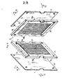
- each fractionation chamber C 1 , C 2 - is formed by two identical panels 15, 16 joined tightly against each other by one of their face 15a, 16b; the semi-permeable membranes 1 and 2 which separate the chamber in question from the two neighboring chambers come under pressure against the other faces of said panels 15b, 16a.
- Each of these panels has a thickness equal to that of half the frame (and therefore equal to half the thickness of the chamber).
- These panels can be made of any dielectric material, neutral vis-à-vis the initial solutions to be treated, for example polymethyl methacrylate.
- Each panel 15 or 16 comprises on a face 15a or 16a a recess 17 or 18 extending along one side of it (for example the upper side in FIG. 3); it comprises on the opposite face 15b or 16b an identical recess 19 or 20 extending along the opposite side (lower side).
- One of these recesses (for example 17) is called to play the role of channel of admission of the initial solution towards the active zone of the room, two other recesses, for example 18 and 19, being called to play the role of channels withdrawal (a recess (20) is in the example unused).
- each frame is each pierced with four corresponding lights such as 21.
- the upper recess of each panel (17 or 18) extends to one of these lights 21 without communication with the other light, while the lower recess (19 or 20) extends to the light located opposite without communication with the other light.
- each semi-permeable membrane is also pierced with four slots such as 22 in correspondence with the slots 21.
- each of the two panels 15 or 16 forming a frame 3 of the fractionation chamber is provided with parallel tabs, such as 23, which extend vertically from one side to the other of the frame until the recesses of that -this ; these tabs 23 thus divide the volume located between these recesses into a plurality of elongated volumes, which constitute the active zones of the chamber. They make it possible to divide the flow of initial solution into a plurality of parallel threads which extend between the two membranes 1 and 2 of the chamber considered: the admission of the initial solution to said threads as well as the withdrawal of the liquid fractions to from these are carried out in parallel by the channels formed by the top and bottom recesses.
- FIG. 4 is a cross section of a chamber at the level of one of the threads (section through a vertical plane BB perpendicular to the frame), the panels 15 and 16 which constitute each frame, form separating elements 15c and 16c at each liquid stream, along the two sides of the frame.
- a separating element 16c separates the upper intake channel formed by the recess 17 from the upper withdrawal channel formed by the recess 19, while the other separation element 15c delimits the lower withdrawal channel formed by the recess. 18.
- these separation elements 15c, 16c are in the form of a bevel as shown in FIG. 4 and are directed from the sampling zones 18 and 19 towards an intermediate zone Zi of the chamber where the convection speed is very low.
- Figure 4 shows the diagram of the convection speeds inside a liquid stream).
- a divergent diffusion element 15d of structure identical to the separation elements 15c or 16c, is formed by the panel 15 to produce a divergent entry of the initial solution.
- the panels 15 and 16 are identical, the panel 16 carries a similar element 16d on the edge of its recess 20, (which has no role in the example described, since the filling has lcun is achieved through this recess 20) .
- FIG. 6 presents a frame 24 which delimits each guard compartment G 1 and G 2 .
- This frame comprises tongues 25 extending vertically from one side to the other of the latter in line with the tongues 23 of the frames 3 of the fractionation chambers; these tabs 25 thus define elongated volumes opposite the active volumes of the chambers.
- the frame 24 is also pierced with supply means 27 for supplying these volumes in parallel giformes in auxiliary solution and de- evacuation means 26 for evacuating in parallel the auxiliary solution after circulation in said volumes.
- the frame of one of the guard compartments (G 1 ) corresponds and communicates with the supply lights (21, 22) in initial solution of the frames and membranes of the fractionation chambers, in order to allow the 'supply of the inlet channels of said chambers, while the other angled lumen 28 corresponds and communicates with the sampling lumens in order to collect a liquid fraction; for the frame of the other guard compartment (G 2 ) (frame arranged in an inverted position relative to the first), one of these lights corresponds and communicates with the lights for taking the other liquid fraction.
- each electrode compartment E, E 2 is similar to the frame 24 described above with the exception of the lights 28 which are not provided there. It makes it possible to circulate an ionic solution eliminating the products formed in contact with the electrodes and to confine the electric field generated to only the active areas of the fractionation chambers and guard compartments (located between their tongues).
- Examples 1, 2, 3, 4 and 5 which follow are intended to illustrate the possibilities of application of the device of the invention as well as its performance;
- Examples 6 and 7 are intended to illustrate the existence of a maximum of the separation factor when varying the thickness of the splitting chambers without changing any other parameters.
- the supply and withdrawal rates formed below are average rates referred to the unit of useful width for a membrane; they are expressed in cm 3 / hour / cm.
- This liquid fraction was obtained by two successive fractionations carried out in two stages in the device.
- the initial solution for feeding the fragmentation chambers is pure bovine serum of pH between 7.5 and 8 and of composition:
- the operating conditions are as follows:
- the solution originating from the bottom of the cell contains 49% of albumin and 20% of ⁇ -globulins.
- the energy consumed to process one liter of initial solution is equal to 57 Watt-hours.
- the second stage consists of a fractionation of the liquid fraction collected at the bottom of the chambers during stage 1. This fraction of high concentration (202.31 g / l) is diluted 7 times before treatment.
- Table II indicates that the top fraction of the chambers contains only ⁇ and ⁇ -globulins. If for Y-globulins the concentration in this fraction (31.10 g / l) is substantially identical to that of the initial feeding serum (26.35 g / 1), for ⁇ -globulins, the concentration in the fraction from the top (2.70 g / 1) is much lower than in the initial feeding serum (13.91 g / 1). The ⁇ -globulins therefore migrate towards the anode, this migration being able to at least partially justify the loss of biological activity of the top sample (200 ⁇ T ⁇ 250 IU / ml) compared to the initial serum (400 ⁇ T ⁇ 450 IU / ml). Note that gold: recovers 59% of the ⁇ -globulins from the initial solution at the top of the chambers, the ⁇ -globulins thus seeming to migrate slightly towards the cathode.
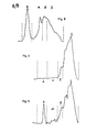
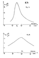
- Figures 8 and 9 present for this example the concentration spectra obtained by analysis on cellulose acetate (IST) respectively for the initial solution (Fig. 8) and for the liquid fraction taken from the top (Fig. 9).
- ⁇ -globulins a low concentration of ⁇ -globulins and traces of albumin (A) (not easy to distinguish on this spectrum).
- Table III which summarizes the results obtained shows that the fraction obtained at the "Top" outlet of the rooms is very much che in ⁇ -globulin (35%) and ⁇ -globulinea (44%).
- the biological activity of this fraction (300 ⁇ T ⁇ 400 IU / ml) is much higher than that measured for the top fraction of Example 1 (200 ⁇ T ⁇ 250 IU / ml). This increase could be due to the relatively high concentration of ⁇ -globulins present in the top fraction (13.83 g / 1 against 13.91 g / 1 in the initial solution). 78% and 52% of the ⁇ -globulins and ⁇ -globulins are respectively recovered from the initial feed solution.
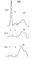
- FIG. 10 shows the concentration spectrum of the top fraction, obtained by analysis on cellulose acetate and illustrates the high concentration of ⁇ -globulins and ⁇ -globulins, with a trace of albumin.
- FIG. 12 shows the concentration spectrum of the high liquid fraction obtained in Example 4 and FIG. 13 the concentration spectrum of the high liquid fraction obtained in Example 5. A slight trace of albumin is observed for both samples analyzed. On the other hand, a high concentration of ⁇ -globulins is noted for the upper fraction of Example 5, a concentration which must certainly be related to the high biological activity of this fraction.
- the curve of FIG. 14 shows that the separation factor (that is to say the ratio of the albumin concentration of the low fraction to the albumin concentration of the high fraction) has a sharp maximum for a distance between membranes. equal to 0.25 cm.
- the optimal conditions can be adjusted by manufacturing frames with a given thickness (in practice within a range of 0.15 to 0.40 cm) and by varying the supply and withdrawal rates until they are in the maximum zone; in the event that these flow rates are imposed by the particular conditions for implementing the application, preliminary tests will be carried out in the laboratory with devices having different frame thicknesses, so as to draw the curve giving the separation factor in depending on this thickness. The final device will be produced by choosing the thickness corresponding to the maximum of this curve.
Landscapes
- Life Sciences & Earth Sciences (AREA)
- Chemical & Material Sciences (AREA)
- Health & Medical Sciences (AREA)
- Molecular Biology (AREA)
- Electrochemistry (AREA)
- Chemical Kinetics & Catalysis (AREA)
- Physics & Mathematics (AREA)
- Environmental & Geological Engineering (AREA)
- Engineering & Computer Science (AREA)
- Analytical Chemistry (AREA)
- Biochemistry (AREA)
- General Health & Medical Sciences (AREA)
- General Physics & Mathematics (AREA)
- Immunology (AREA)
- Pathology (AREA)
- Separation Using Semi-Permeable Membranes (AREA)
- Peptides Or Proteins (AREA)
Abstract
Le dispositif de fractionnement conforme à l'invention pour séparer au moins deux groupes de substances dissoutes dans une solution est du type dans lequel on applique un champ électrique dans des chambres de fractionnement séparées par des membranes semi-perméables, de façon à engendrer des migrations différentes des divers groupes de substances ; chaque chambre de fractionnement est délimitée par un cadre périphérique 3 pourvu d'une pluralité de languettes 23 ; les deux membranes semi-perméables 1 et 2 de la chambre sont appliquées de part et d'autre contre les faces dudit cadre et contre les faces desdites languettes : de part et d'autre des chambres de fractionnement, des compartiments de garde sont avantageusement prévus, contenant une solution auxiliaire apte à accentuer, par des échanges ioniques à vitesse élevée, les différences de migrations des substances à séparer.
Description
L'invention concerne un dispositif de fractionnement d'une solution en vue de séparer au moins deux groupes de substances dissoutes dans celle-ci ; elle vise un dispositif de fractionnement par électrophorèse, utilisant un champ électrique pour produire une migration des substances.The invention relates to a device for fractionating a solution in order to separate at least two groups of substances dissolved in it; it targets an electrophoresis fractionation device, using an electric field to produce a migration of substances.
On a déjà utilisé en laboratoire l'électrophorèse pour fractionner une solution et obtenir des fractions liquides, enrichies en substances contenues dans la solution initiale ; t'intérêt essentiel de ce type de procédé est qu'il conserve les propriétés spécifiques des substances fractionnées sans les dénaturer et également qu'il conduit à de faibles consommations énergétiques. On pourra en particulier se reporter au brevet FR publié sous le n° 2 131 859 ou au brevet US n° 2 801 962 ou au brevet US n° 2 878 178 ou encore au brevet US n° 3 989 613 ou encore au brevet US 936 805 pour prendre connaissance de plusieurs modes de réalisation de dispositifspermettant la mise en oeuvre de tels procédés d'électrophorèse.Electrophoresis has already been used in the laboratory to fractionate a solution and obtain liquid fractions, enriched with substances contained in the initial solution; the main interest of this type of process is that it retains the specific properties of the fractionated substances without denaturing them and also that it leads to low energy consumption. Reference may in particular be made to the FR patent published under No. 2 131 859 or to US Patent No. 2 801 962 or to US Patent No. 2 878 178 or even to US Patent No. 3 989 613 or even to US Patent 936 805 to learn about several embodiments of devices allowing the implementation of such electrophoresis methods.
Toutefois, ces dispositifs ne permettent d'obtenir que des rendements relativement médiocres, les durées de fonctionnement nécessaires pour obtenir un taux de fractionnement donné étant souvent très longues.However, these devices allow only relatively poor yields to be obtained, the operating times required to obtain a given fractionation rate often being very long.
Ainsi, en pratique, les dispositifs connus ne permettent pas de profiter pleinement des avantages que fournissent les procédés d'électrophorèse (faible consommation énergétique, absence de dénaturation des substances fractionnées) en raison des défauts inhérant à chacun de ces dispositifs, qui s'opposent,à une mise en oeuvre industrielle. De plus, pour la plupart des dispositifs de fractionnement connus, il est nécessaire d'effectuer une préparation préalable de la solution initiale qui doit être diluée et dialysée, en général pour ajuster son pH, en vue d'autoriser un fractionnement efficace. Ces opérations de dialyse sont longues et délicates et sources de contaminations bactériennes des solutions.Thus, in practice, the known devices do not make it possible to take full advantage of the advantages that the electrophoresis processes provide (low energy consumption, absence of denaturation of the fractionated substances) due to the inherent defects in each of these devices, which are opposed , to an industrial implementation. In addition, for most of the known fractionation devices, it is necessary to carry out a preliminary preparation of the initial solution which must be diluted and dialyzed, in general to adjust its pH, in order to allow effective fractionation. These dialysis operations are long and delicate and sources of bacterial contamination of the solutions.
La présente invention se propose de supprimer les défauts des dispositifs connus de fractionnement par électrophorèse, afin de permettre de profiter pleinement des avantages de l'électrophorèse.The present invention proposes to suppri mer the shortcomings of known devices for fractionation by electrophoresis, in order to fully enjoy the benefits of electrophoresis.
Un objectif essentiel de l'invention est d'améliorer considérablement l'efficacité des dispositifs, de façon à atteindre des taux de fractionnement élevés avec des durées de fonctionnement relativement faibles, compatibles avec une mise en oeuvre à échelle industrielle.An essential objective of the invention is to considerably improve the efficiency of the devices, so as to achieve high fractionation rates with relatively short operating times, compatible with implementation on an industrial scale.
Un autre objectif est de fournir un dispositif susceptible d'être fabriqué à faible coût.Another objective is to provide a device capable of being manufactured at low cost.
Un autre objectif est de permettre d'effectuer le fractionnement en continu.Another objective is to allow fractionation to be carried out continuously.
Un autre objectif est d'étendre les possibilités d'application des procédés de fractionnement par. électrophorèse, grâce à l'amélioration considerable de l'efficacité des dispositifs conformes à l'invention.Another objective is to extend the possibilities of application of the fractionation processes by. electrophoresis, thanks to the considerable improvement in the efficiency of the devices according to the invention.
Un autre objectif est d'éliminer radicalement toute étape préalable de dialyse ou touteautre préparation de type analogue.Another objective is to radically eliminate any prior step of dialysis or any other similar type of preparation.
A cet effet, le dispositif de fractionnement par électrophorèse visé par l'invention est du type comprenant des électrodes pour générer un champ électrique et, entre celles-ci, au moins deux membranes semi-perméables délimitant au moins une chambre de fractionnement dotée de moyens d'admission de a solution et de moyens de soutirage des fractions liquides; selon la présente invention chaque chambre de fractionnement est délimitée par un cadre périphérique pourvu d'une pluralité de languettes réunissant deux côtés dudit cadre et présentant la même épaisseur que celui-ci, les deux membranes semi-perméables étant appliquées, de part et d'autre, contre les faces dudit cadre et contre les faces desdites languettes de façon que ces membranes soient maintenues séparées d'une distance constante sur toute leur surface et que le volume compris entre lesdites membranes soit divisé par les languettes en une pluralité de volumes longiformes.To this end, the electrophoresis fractionation device targeted by the invention is of the type comprising electrodes for generating an electric field and, between them, at least two semi-permeable membranes delimiting at least one fractionation chamber provided with means admission of a solution and means for withdrawing liquid fractions; according to the present invention each fractionation chamber is delimited by a peripheral frame provided with a plurality of tabs joining two sides of said frame and having the same thickness as the latter, the two semi-permeable membranes being applied, on both sides other, against the faces of said frame and against the faces of said tongues so that these membranes are kept separated by a constant distance over their entire surface and that the volume comprised between said membranes is divided by the tongues into a plurality of elongated volumes.
Les expérimentations ont permis de constater que le rendement de fractionnement est considérablement augmenté dans le dispositif de l'invention, essentiellement pour les raisons suivantes :
- . la structure de ce dispositif permet de limiter les zones mortes dans chaque chambre de fractionnement en canalisant l'écoulement dans des volumes relativement étroits,
- . cette structure permet également d'assurer un écoulement laminaire dans les chambres et d'éviter ainsi un remélange des substances séparées (provoqué dans les dispositifs connus par l'apparition de turbulences),
- . enfin, cette structure assure un excellent maintien des membranes sur toute leur surface et permet de rapprocher celles-ci avec un faible écart constant quelles que soient le.s zones considérées.
- . the structure of this device makes it possible to limit the dead zones in each fractionation chamber by channeling the flow in relatively narrow volumes,
- . this structure also makes it possible to ensure a laminar flow in the chambers and thus to avoid remixing of the separated substances (caused in known devices by the appearance of turbulence),
- . finally, this structure provides excellent retention of the membranes over their entire surface and allows them to be brought together with a constant small difference whatever the areas considered.
Comme on le comprendra mieux plus loin, ce dernier effet est essentiel en pratique, car non seulement il conditionne un meilleur échange entre les chambres de fractionnement voisines, mais encore et surtout,il donne la possibilité d'augmenter considérablement le rendement à l'intérieur de chaque chambre ; en effet, les essais ont montré que, pour des substances déterminées et desdébits d'admission et de soutirage donnés, la courbe donnant les variations du rendement de fractionnement (ou encore du facteur de séparation) présente un maximum pointu pour une valeur déterminée de l'épaisseur des chambres ; par exemple dans le cas d'une solution initiale contenant de l'albumine, qui est fractionnée pour obtenir une fraction enrichie en ce corps, la valeur maximum du facteur de séparation est obtenue dans une plage d'épaisseur sensiblement comprise entre 0,15 et 0,40 cm en fonction des débits prévus.As will be better understood later, this last effect is essential in practice, because not only does it condition a better exchange between the neighboring fractionation chambers, but also and above all, it gives the possibility of considerably increasing the yield inside. from each room; indeed, tests have shown that, for given substances and given intake and withdrawal rates, the curve giving the variations in the fractionation efficiency (or even the separation factor) has a sharp maximum for a determined value of l 'thickness of the chambers; for example in the case of an initial solution containing albumin, which is fractionated to obtain a fraction enriched in this body, the maximum value of the separation factor is obtained in a thickness range substantially between 0.15 and 0.40 cm depending on the expected flow rates.
La structure du dispositif conforme à l'invention, grâce au guidage parfait des membranes sur toute leur surface, permet d'ajuster de façon très précise la distance entre celles-ci (et donc l'épaisseur des chambres de fractionnement), de façon à se placer dans chaque cas dans la zone du maximum de séparation.The structure of the device according to the invention, thanks to the perfect guidance of the membranes over their entire surface, makes it possible to very precisely adjust the distance between them (and therefore the thickness of the fractionation chambers), so as to in each case, place yourself in the maximum separation zone.
Par ailleurs, selon une autre caractéristique de l'invention venant se combiner à celles déjà décrites, des compartiments de garde sont disposés entre chaque électrode et la chambre de fractionnement extrême correspondante ; ces compartiments sont associés à des moyens d'alimentation en une solution auxiliaire et à des moyens d'évacuation de celle-ci. Ils sont délimités par un cadre muni de languettes analogues à celles déjà évoquées, la membrane du compartiment d'électrodes venant en appui contre une face dudit cadre et une face desdites languettes, cependant que la membrane de la chambre de fractionnement extrême vient en appui contre l'autre face dudit cadre et l'autre face desdites languettes. Les languettes dudit cadre sont disposées au droit des languettes des cadres des chambres de fractionnement, en vue de former des volumes longiformes situés en regard des volumes correspondants desdites chambres.Furthermore, according to another characteristic of the invention coming to combine with those already described, guard compartments are arranged between each electrode and the corresponding extreme fractionation chamber; these compartments are associated with food means tation in an auxiliary solution and means of evacuation thereof. They are delimited by a frame provided with tongues similar to those already mentioned, the membrane of the electrode compartment coming to bear against one face of said frame and one face of said tongues, while the membrane of the extreme fractionation chamber comes to bear against the other side of said frame and the other side of said tabs. The tongues of said frame are arranged in line with the tongues of the frames of the fractionation chambers, with a view to forming elongated volumes located opposite the corresponding volumes of said chambers.
Ainsi, dans un tel dispositif, le champ électrique servant au fractionnement sert également à engendrer des échanges ioniques rapides à travers les membranes entre la solution initiale contenue dans les diverses chambres de fractionnement et la solution auxiliaire contenue dans les compartiments de garde. On supprime ainsi radicalement les opérations de préparation préalables, notamment de dialyse qui sont nécessaires dans certains dispositifs classiques, ainsi que tous les inconvénients afférents ; de plus, la solution initiale n'a plus à être diluée et le procédé peut s'appliquer à des solutions naturelles dans l'état où elles sont produites ou recueillies. Par exemple, le procédé peut être appliqué directement à du sérum ou du plasma sanguin, ce qui écarte toutes les manipulations et précautions requises par l'étape de dilution.Thus, in such a device, the electric field used for fractionation also serves to generate rapid ion exchanges through the membranes between the initial solution contained in the various fractionation chambers and the auxiliary solution contained in the guard compartments. This radically eliminates the preliminary preparation operations, in particular dialysis which are necessary in certain conventional devices, as well as all the associated drawbacks; moreover, the initial solution no longer has to be diluted and the process can be applied to natural solutions in the state in which they are produced or collected. For example, the method can be applied directly to serum or blood plasma, which eliminates all the manipulations and precautions required by the dilution step.
Les caractéristiques essentielles de la solution initiale dont dépendent les différences de migrations entre substances sont constituées par son pH et sa concentration saline. En conséquence, la concentration et la nature des ions de la solution auxiliaire sont choisies dans chaque application de façon à réaliser des échanges ioniques aptes à conditionner un pH et une concentration saline adaptés de la solution initiale. Ce choix dépend des substances en présence et peut être effectué au terme de tests préalables avec plusieurs solutions auxiliaires contenant différents types d'ions à différentes concentrations et à différents pH. Par exemple, on peut utiliser les ions suivants : ions phosphates (ions de Na2 HP043 de KH2 P04, de K 2 H P0 4, Na H2 P04...), ions carbonates, ions du barbital, ions acé- tates etc...The essential characteristics of the initial solution on which the differences in migration between substances depend are constituted by its pH and its salt concentration. Consequently, the concentration and the nature of the ions of the auxiliary solution are chosen in each application so as to carry out ionic exchanges capable of conditioning a suitable pH and saline concentration of the initial solution. This choice depends on the substances present and can be made after preliminary tests with several auxiliary solutions containing different types of ions at different concentrations and at different pH. For example, the following ions can be used: phosphate ions (ions of Na 2 HP0 4 3 of KH 2 P0 4 , of K 2 H P0 4 , Na H 2 P0 4 ...), carbonate ions, barbital ions, ions c E- tates etc ...
Le dispositif de l'invention permet une mise en oeuvre en continu du procédé d'électrophorèse, en effectuant une admission continue de la solution initiale et des prélèvements continus des fractions liquides et en engendrant une circulation de la solution auxiliaire à l'arrière de la ou des membranes semi-perméables correspondantes, de façon à renouveler ladite solution en continu en vue de préserver une concentration ionique sensiblement constante à ladite solution.The device of the invention allows a continuous implementation of the electrophoresis process, by carrying out a continuous admission of the initial solution and continuous withdrawals of the liquid fractions and by generating a circulation of the auxiliary solution behind the or corresponding semi-permeable membranes, so as to renew said solution continuously in order to preserve a substantially constant ion concentration in said solution.
L'invention ayant été exposée dans sa forme générale, d'autres caractéristiques, buts et avantages, se dégageront de la description qui suit, laquelle fournit, en référence aux dessins annexés, d'une part, un mode de réalisation préférentiel du dispositif de l'invention, d'autre part, des exemples d'électrophorèse mis en oeuvre à l'aide dudit dispositif ; sur ces dessins qui font partie intégrante de la description :
- . la figure 1 est une vue en perspective d'un dispositif conforme à l'invention,
- . la figure 2 en est une vue partielle en coupe par un plan vertical A,
- . la figure 3 est une vue schématique en perspective des éléments constitutifs qui délimitent une chambre de fractionnement, figure dans laquelle ces éléments constitutifs sont dessinés écartés les uns des autres pour faciliter la compréhension,
- . la figure 4 est une coupe, à échelle très dilatée, de cette chambre en état de fonctionnement, par un plan vertical BB, avec schématisation symbolique du diagram- mé des vitesses de convection,
- . la figure 5 est une coupe de ladite chambre par un plan horizontal CC,
- . la figure 6 est une vue en perspective d'un cadre utilisé pour former un compartiment de garde,
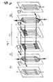
- . la figure 7.est un schéma éclaté, montrant les circulations de liquide dans le dispositif,
- . les figures 8 à 13 donnent des spectres d'analyse illustrant les résultats obtenus dans les exemples de mise en
oeuvre 1 à 5, - . les figures 14 et 15 fournissent les courbes donnant le facteur de séparation en fonction de l'épaisseur des chambres de fractionnement dans les exemples 6 et 7.
- . FIG. 1 is a perspective view of a device according to the invention,
- . FIG. 2 is a partial view thereof in section through a vertical plane A,
- . FIG. 3 is a schematic perspective view of the constituent elements which delimit a fractionation chamber, a figure in which these constituent elements are drawn apart from one another to facilitate understanding,
- . FIG. 4 is a section, on a very expanded scale, of this chamber in operating condition, by a vertical plane BB, with symbolic diagrammatic diagram of the diagram of convection speeds,
- . FIG. 5 is a section through said chamber by a horizontal plane CC,
- . FIG. 6 is a perspective view of a frame used to form a guard compartment,
- . FIG. 7 is an exploded diagram showing the circulation of liquid in the device,
- . Figures 8 to 13 give spectra of analysis illustrating the results obtained in the examples of
implementation 1 to 5, - . FIGS. 14 and 15 provide the curves giving the separation factor as a function of the thickness of the fractionation chambers in Examples 6 and 7.
Le dispositif représenté à titre d'exemple aux figures 1 à 7 comprend plusieurs chambres de fractionnement C1, C21 C3 accolées, appelées à contenir la solution initiale à fractionner, deux compartiments de garde G,, G2 disposés de part et d'autre des deux chambres extrêmes et appelés à contenir une solution auxiliaire, et deux compartiments d'électrode E1,. E2 disposés de part et d'autre des compartiments de garde et appelés à contenir une solution ionique.The device shown by way of example in FIGS. 1 to 7 comprises several fractionation chambers C 1 , C 2 1 C 3 joined together, called to contain the initial solution to be fractionated, two guard compartments G ,, G 2 arranged on the side and on the other, the two extreme chambers called to contain an auxiliary solution, and two compartments of electrode E 1 ,. E 2 arranged on either side of the guard compartments and called to contain an ionic solution.
Chaque chambre de fractionnement C1, C2, C3 est délimitée sur deux grandes faces par deux membranes telles que 1 et 2 (fig. 2, 3, 4, 5) qui sont communes aux deux chambres voisines et permettent de la séparer de celles-ci. En outre, chaque chambre est délimitée sur son pourtour par .un cadre 3 contre lequel les membranes 1 et 2 sont appliquées étanchément. Ces cadres seront décrits en détail plus loin.Each fractionation chamber C 1 , C2, C3 is delimited on two large faces by two membranes such as 1 and 2 (fig. 2, 3, 4, 5) which are common to the two neighboring chambers and allow it to be separated from them. this. In addition, each chamber is delimited on its periphery by a
De façon analogue, chaque compartiment de garde G1 ou G2 est séparé, d'une part, de la chambre de fractionnement voisine par une membrane semi-perméable 4 identique à celles qui séparent les chambres, d'autre part du compartiment d'électrode voisin par une membrane semi-perméable 5 identique ; en outre, chaque compartiment de garde est délimité sur son pourtour par un cadre 6 contre lequel les membranes 4 et 5 sont appliquées étanchément ; ces cadres seront décrits en détail plus loin.Similarly, each guard compartment G 1 or G 2 is separated, on the one hand, from the neighboring fractionation chamber by a semi-permeable membrane 4 identical to those which separate the chambers, on the other hand from the compartment neighboring electrode by an identical
Chaque compartiment d'électrode E1 ou E2 est délimité sur ses grandes faces par la membrane 5 qui le sépare du compartiment de garde et par un panneau latéral 7 comportant sur une face interne un revêtement conducteur 8, formant l'électrode et connecté à une source électrique. Sur son pourtour, chaque compartiment d'électrode est délimité par un cadre 9 similaire au cadre 6 du compartiment de garde (à l'exception de lumières d'alimentation ou de prélèvement dont il est exempt).Each electrode compartment E 1 or E 2 is delimited on its large faces by the
En l'exemple, les membranes, cadres et panneaux latéraux sont de forme rectangulaire et forment un empilement guidé par des tiges telles que 10 et maintenu en pression par des plaques 11 et 12. L'une des plaques 12 est fixée à un support 13, cependant que l'autre 11 est mobile et est associée à un organe de serrage manuel classique 14 qui permet d'appliquer une pression entre les plaques pour assurer le maintien et l'étanchéité de l'empilage.In the example, the membranes, frames and side panels are rectangular in shape and form a stack guided by rods such as 10 and kept in pressure by
Comme le représentent les figures 3, 4 et 5, le cadre 3 de chaque chambre de fractionnement C1, C2--est formé de deux panneaux identiques 15, 16 accolés étanchément l'un contre l'autre par une.de leur face 15a, 16b ; les membranes semi-perméables 1 et 2 qui séparent la chambre considérée des deux chambres voisines, viennent en pression contre les autres faces desdits panneaux 15b, 16a. Chacun de ces panneaux présente une épaisseur égale à celle de la moitié du cadre (et donc égale à la moitié de l'épaisseur de la chambre). Ces panneaux peuvent être réalisés en tout matériau diélectrique, neutre vis-à-vis dessolutions initiales à traiter, par exemple en polyméthacrylate de méthyle.As shown in Figures 3, 4 and 5, the
Chaque panneau 15 ou 16 comprend sur une face 15a ou 16a un évidement 17 ou 18 s'étendant le long d'un côté de celui-ci (par exemple côté supérieur à la figure 3) ; il comprend sur la face opposée 15b ou 16b un évidement identique 19 ou 20 s'étendant le long du côté opposé (côté inférieur).Each
Un de ces évidements (par exemple 17) est appelé à jouer le rôle de canal d'admission de la solution initiale vers la zone active de la chambre, deux autres évidements, par exemple 18 et 19, étant appelés à jouer le rôle de canaux de soutirage (un évidement (20) est en l'exemple inutilisé).One of these recesses (for example 17) is called to play the role of channel of admission of the initial solution towards the active zone of the room, two other recesses, for example 18 and 19, being called to play the role of channels withdrawal (a recess (20) is in the example unused).
En outre, les panneaux 15 et 16 formant chaque cadre sont chacun percés de quatre lumières en correspondance telles que 21. L'évidement supérieur de chaque panneau (17 ou 18) se prolonge jusqu'à l'une de ces lumières 21 sans communication avec l'autre lumière, cependant que l'évidement inférieur (19 ou 20) se prolonge jusqu'à la lumière située à l'opposé sans communicàtion avec l'autre lumière.In addition, the
Ces lumières permettront d'alimenter en parallèle, en solution initiale, les canaux d'admission des diverses chambres (formés par les évidements 17) et de prélever les fractions liquides à partir des canaux de soutirage de celles-ci (formés par les évidements 18 et 19). Pour permettre cette alimentation ou ce soutirage, chaque membrane semi-perméable est également percée de quatre lumières telles que 22 en correspondance avec les lumières 21.These lights will make it possible to supply in parallel, in initial solution, the admission channels of the various chambers (formed by the recesses 17) and to collect the liquid fractions from the withdrawal channels of these (formed by the
De plus, chacun des deux panneaux 15 ou 16 formant un cadre 3 de chambre de fractionnement est pourvu de languettes parallèles, tels que 23, qui s'étendent verticalement d'un côté à 1-'autre du cadre jusqu'aux évidements de celui-ci ; ces languettes 23 divisent ainsi le volume situé entre ces évidements en une pluralité de volumes longiformes, qui constituent les zones actives de la chambre. Ils permettent de diviser le flux de solution initiale en une pluralité de filets parallèles qui s'étendent entre les deux membranes 1 et 2 de la chambre considérée : l'admission de la solution initiale vers lesdits filets de même que le soutirage des fractions liquides à partir de ceux-ci s'effectuent en parallèles par les canaux formés par les évidements haut et bas.In addition, each of the two
Ces dispositions présentent l'avantage de limiter les zones mortes dans la chambre, en canalisant l'écoulement dans des volumes relativement étroits, ce qui accroit l'efficacité du fractionnement. De plus, les membranes semi-perméables viennent en appui contre les faces des languettes 23 et sont parfaitement maintenues sans risque de déformation sensible, ce qui permet de les disposer à des distances très précises les unes des autres, distances pouvant être très faibles (en pratique de l'ordre de 0,2 à 0,3 cm pour correspondre au maximum de rendement de séparation comme on le verra plus loin).These arrangements have the advantage of limiting the dead zones in the chamber, by channeling the flow in relatively narrow volumes, which increases the efficiency of the fractionation. In addition, the semi-permeable membranes bear against the faces of the
Par ailleurs, comme on peut l'apercevoir clairement à la figure 4 qui est une coupe transversale d'une chambre au niveau d'un des filets (coupe par un plan vertical BB perpendiculaire au cadre), les panneaux 15 et 16 qui constituent chaque cadre, forment des éléments de séparation 15c et 16c au niveau de chaque filet liquide, le long des deux côtés du cadre.Furthermore, as can be clearly seen in FIG. 4 which is a cross section of a chamber at the level of one of the threads (section through a vertical plane BB perpendicular to the frame), the
Un élément de séparation 16c sépare le canal j'admission supérieur formé par l'évidement 17 du canal de soutirage supérieur formé par l'évidement 19, cependant que l'autre élément de séparation 15c délimite le canal de soutirage inférieur formé par l'évidemept 18.A separating
En l'exemple, ces éléments de séparation 15c, 16c sont en forme de biseau comme le montre la figure 4 et sont dirigés depuis les zones de prélèvement 18 et 19 vers une zone intermédiaire Zi de la chambre où la vitesse de convection est très faible (On a représenté symboliquement à la figure 4 le diagramme des vitesses de convection à l'intérieur d'un filet liquide).In the example, these
Il est à noter en outre qu'un élément de diffusion divergent 15d, de structure identique aux éléments de séparation 15c ou 16c,est formé par le panneau 15 pour réaliser une entrée divergente de la solution initiale. Les panneaux 15 et 16 étant identiques, le panneau 16 porte un élément similaire 16d en bordure de son évidement 20, (qui n'a aucun rôle dans l'exemple décrit puisque allcun soutirage n'est réalisé à travers cet évidement 20).It should also be noted that a
Les dispositions ci-dessus décrites permettent de réaliser un cadre 3 très bon marché, à partir de deux panneaux identiques (qui sont simplement accolés l'un sur l'autre après renversement et retournement à partir de leur position de superposition) et confèrent à chaque chambre C1, C2 un taux de fractionnement maximum (toute chose étant égale par ailleurs) provenant du réglage précis de l'épaisseur des chambres, des remélanges réduits entre fractions séparées et solution initiale, de l'absence de déformations des membranes semi-perméables et de la limitation des zones mortes.The arrangements described above make it possible to produce a very
Par ailleurs, la figure 6 présente un cadre 24 qui délimite chaque compartiment de garde G1 et G2. Ce cadre comprend des languettes 25 s'étendant verticalement d'un côté à l'autre de celui-ci au droit des languettes 23 des cadres 3 des chambres de fractionnement ; ces languettes 25 définissent ainsi des volumes longiformes en regard des volumes actifs des chambres.Furthermore, FIG. 6 presents a
Le cadre 24 est en outre percé de moyens d'alimentation 27 pour alimenter en parallèles ces volumes longiformes en solution auxiliaire et de- moyens d'évacuation 26 pour évacuer en parallèles la solution auxiliaire après circulation dans lesdits volumes.The
En outre, il est percé de deux lumières coudées telles que 28 ; pour le cadre d'un des compartiments de garde (G1), une de ces lumières correspond et communique avec les lumières d'alimentation (21, 22) en solution initiale des cadres et membranes des chambres de fractionnement, en vue de permettre l'alimentation des canaux d'admission desdites chambres, cependant que l'autre lumière coudée 28 correspond et communique avec les lumières de prélèvement en vue de recueillir une fraction liquide ; pour le cadre de l'autre compartiment de garde (G2) (cadre disposé en position retournée par rapport au premier), l'une de ces lumières correspond et communique avec les lumières de prélèvement de l'autre fraction liquide.In addition, it is pierced with two bent lights such as 28; for the frame of one of the guard compartments (G 1 ), one of these lights corresponds and communicates with the supply lights (21, 22) in initial solution of the frames and membranes of the fractionation chambers, in order to allow the 'supply of the inlet channels of said chambers, while the other
Le cadre disposé dans chaque compartiment d'électrode E , E2 est similaire au cadre 24 ci-dessus décrit à l'exception des lumières 28 qui n'y sont pas prévues. Il permet de faire circuler une solution ionique éliminant les produits formés au contact des électrodes et de cantonner le champ électrique généré aux seules zones actives des chambres de fractionnement et compartiments de garde (situées entre leurs languettes).The frame disposed in each electrode compartment E, E 2 is similar to the
La figure 7 schématise la circulation des divers liquides (une seule chambre de fractionnement étant représentée) ; on y retrouve les trajets de circulation :
- . de la solution initiale (en traits continus),
- . des deux fractions liquides séparées (en traits discontinus),
- . des solutions auxiliaires dans les deux compartiments de garde (en pointillés épais),
- . des solutions ioniques dans les deux compartiments d'électrodes (en pointillés fins).
- . the initial solution (in solid lines),
- . two separate liquid fractions (in broken lines),
- . auxiliary solutions in the two guard compartments (thick dotted lines),
- . ionic solutions in the two electrode compartments (dotted lines).
Les exemples 1, 2, 3, 4 et 5 qui suivent sont destinés à illustrer les possibilités d'application du dispositif de l'invention ainsi que ses performances ; les exemples 6 et 7 sont destinés à illustrer l'existence d'un maximum du facteur de séparation lorsqu'on fait varier l'épaisseur des chambres de fractionnement sans modification des autres paramètres.Examples 1, 2, 3, 4 and 5 which follow are intended to illustrate the possibilities of application of the device of the invention as well as its performance; Examples 6 and 7 are intended to illustrate the existence of a maximum of the separation factor when varying the thickness of the splitting chambers without changing any other parameters.
Les exemples 1 à 5 ont été mis en oeuvre dans un dispositif du type ci-dessus décrit, avec les paramètres suivants :
- . nombre de chambre de fractionnement : 5
- . nombre de filets liquides entre languettes dans chaque chambre : 11,
- . surface active de chaque membrane : 60 cm2,
- . épaisseur d'une chambre : 3 mm,
- . solution ionique dans les compartiments d'électrode : même nature que la solution auxiliaire avec une concentration saline double.
- . number of fractionation chambers: 5
- . number of liquid fillets between tabs in each room: 11,
- . active surface of each membrane: 60 cm2,
- . thickness of a chamber: 3 mm,
- . ionic solution in the electrode compartments: same nature as the auxiliary solution with a double salt concentration.
Les débits d 'alimentation et de soutirage formés ci-après sont des débits moyens rapportés à l'unité de largeur utile pour une membrane ; ils sont exprimés en cm3/heure/cm.The supply and withdrawal rates formed below are average rates referred to the unit of useful width for a membrane; they are expressed in cm 3 / hour / cm.
Cette fraction liquide a été obtenue par deux fractionnements successifs réalisés en deux étapes dans le dispositif.This liquid fraction was obtained by two successive fractionations carried out in two stages in the device.
La solution auxiliaire circulant dans les compartiments de garde est un mélange de Na2H PO4 - KH2PO4 à une concentration saline CT = 0,10 M et à un pH = 6,00.The auxiliary solution circulating in the guard compartments is a mixture of Na 2 H PO 4 - KH 2 PO 4 at a salt concentration C T = 0.10 M and at a pH = 6.00.
La solution initiale d'alimentation des chambres de fragmentation est du sérum bovin pur de pH compris entre 7,5 et 8 et de composition :


Les conditions opératoires sont les suivantes :

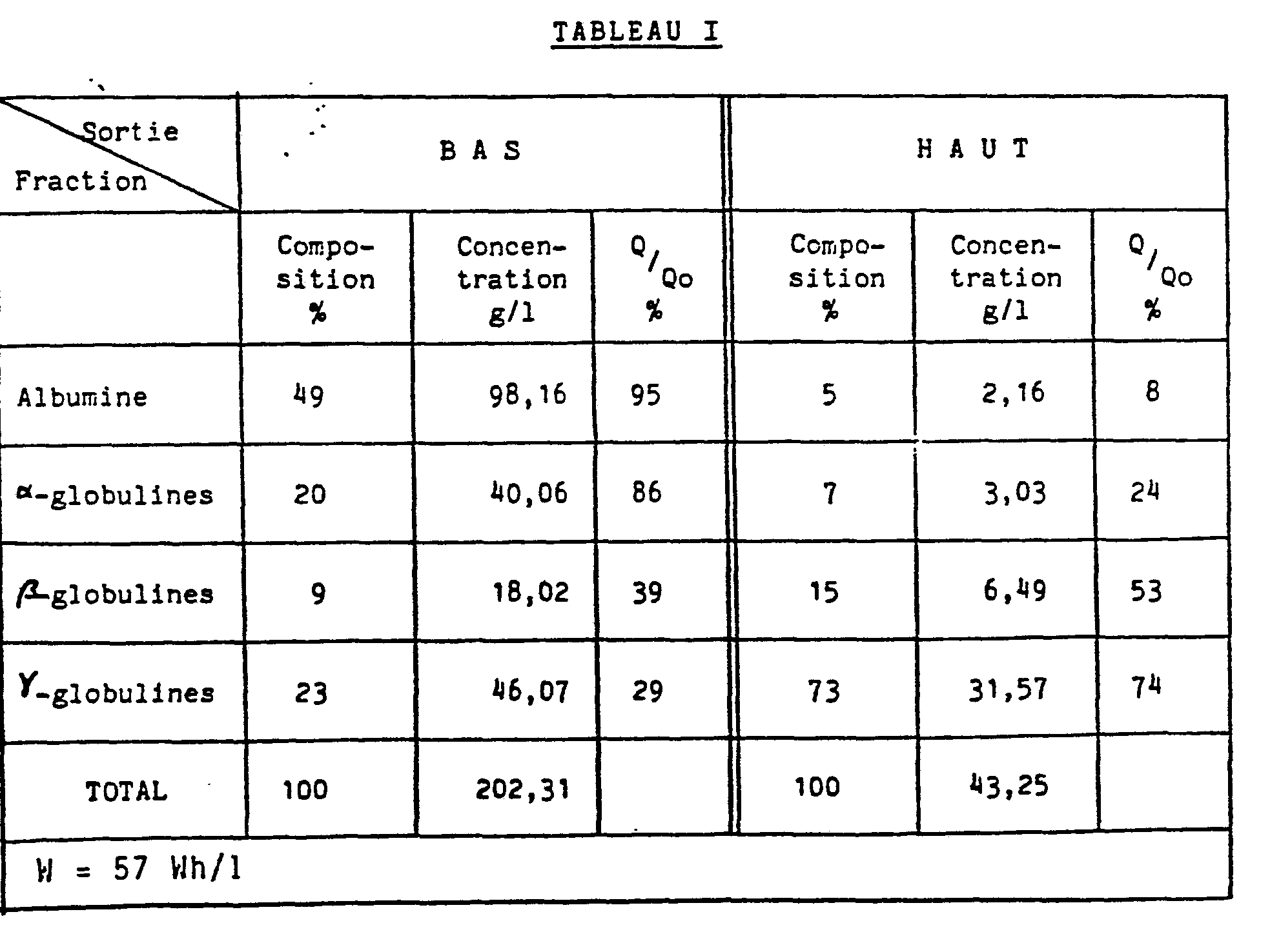
Les résultats de cette étape sont résumés dans le tableau I ci-après (Q/Qo représente le rapport de la quantité de substance récupérée dans la fraction considérée à la quantité présente dans la solution initiale).The results of this step are summarized in Table I below ( Q / Qo represents the ratio of the quantity of substance recovered in the fraction considered to the quantity present in the initial solution).
On constate que la solution provenant du bas de la cellule contient 49 % d'albumine et 20 % d' α-globulines. L'énergie consommée pour traiter un litre de solution initiale est égale à 57 Watt-heure.
La seconde étape consiste en un fractionnement de la fraction liquide recueillie au bas des chambres au cours de l'étape 1. Cette fraction de concentration élevée (202,31 g/l), est diluée 7 fois avant traitement.The second stage consists of a fractionation of the liquid fraction collected at the bottom of the chambers during
Conditions opératoires
- - solution auxiliaire circulant dans les compartiments de garde :

- - solution d'alimentation des chambres de fractionnement : fraction bas de l'étape 1 (diluée 7 fois dans une solution de Na2HPO4 - KH2PO4 (CT = 0,10 M pH = 6,00) de composition :

- - auxiliary solution circulating in the guard compartments:
- - feed solution for the fractionation chambers: bottom fraction of step 1 (diluted 7 times in a solution of Na 2 HPO 4 - KH 2 PO 4 (C T = 0.10 M pH = 6.00) of composition :
L'examen du tableau I Bis ci-dessous qui résume les résultats obtenus montre que l'on obtient des fractions riches en albumine (62 %) et α-globulines (23 %). Sur l'ensemble des deux étapes, 70 % de l'albumine et 58 % des α-globulines présentes dans la solution initiale sont récupérés dans les fractions bas.

Conditions opératoires
- - solution auxiliaire circulant dans les compartiments de garde :

- - solution initiale d'alimentation des chambres de fractionnement : sérum bovin pur,de composition:

- - auxiliary solution circulating in the guard compartments:
- - initial solution for feeding the fractionation chambers: pure bovine serum, of composition:
Activité biologique antitétanique T : 400 < T < 450 U.l/ml
- - d = 4,32 cm3/h.cm
- - dH = dB = 2,16 cm3/h.cm
- - ΔVm= 10,79 v
- - I = 1,56 A
- - d = 4.32 cm 3 /h.cm
- - d H = dB = 2.16 cm 3 /h.cm
- - ΔVm = 10.79 v
- - I = 1.56 A
Le tableau II indique que la fraction du haut des chambres ne renferme que des ρ et γ-globulines. Si pour les Y-globulines la concentration dans cette fraction (31,10 g/l) est sensiblement identique à celle du sérum initial d'alimentation (26,35 g/1), pour les β-globulines, la concentration dans la fraction du haut (2,70 g/1) est bien plus faible que dans le sérum initial d'alimentation (13,91 g/1). Les β-globulines migrent donc vers l'anode, cette migration pouvant au moins partiellement justifier la perte d'activité biologique de l'échantillon du haut (200 < T < 250 U.I/ml) par rapport au sérum initial (400 < T < 450 U.I./ml). Notons que l'or: récupère en haut des chambres 59 % des γ-globulines de la solution initiale, les γ-globulines semblant ainsi migrer légèrement vers la cathode.Table II indicates that the top fraction of the chambers contains only ρ and γ-globulins. If for Y-globulins the concentration in this fraction (31.10 g / l) is substantially identical to that of the initial feeding serum (26.35 g / 1), for β-globulins, the concentration in the fraction from the top (2.70 g / 1) is much lower than in the initial feeding serum (13.91 g / 1). The β-globulins therefore migrate towards the anode, this migration being able to at least partially justify the loss of biological activity of the top sample (200 <T <250 IU / ml) compared to the initial serum (400 <T < 450 IU / ml). Note that gold: recovers 59% of the γ-globulins from the initial solution at the top of the chambers, the γ-globulins thus seeming to migrate slightly towards the cathode.
Les figures 8 et 9 présentent pour cet exemple les spectres de concentration obtenus par analyse sur acétate de cellulose (IST) respectivement pour la solution initiale (Fig. 8) et pour la fraction liquide prélevée en partie haute (Fig. 9). On observe la forte prédominance des γ-globulines, une faible concentration en β-globulines et des traces d'albumine (A) (peu facilesà distinguer sur ce spectre).Figures 8 and 9 present for this example the concentration spectra obtained by analysis on cellulose acetate (IST) respectively for the initial solution (Fig. 8) and for the liquid fraction taken from the top (Fig. 9). We observe the strong predominance of γ-globulins, a low concentration of β-globulins and traces of albumin (A) (not easy to distinguish on this spectrum).

Conditions opératoires
- - solution auxiliaire circulant dans les compartiments de garde et solution initiale d'alimentation des chambres de fractionnement : identiques à celles de l'exemple 1.
- - d = 3,8 cm3/h.cm
- - dH = 3 cm3/h.cm
- - dB = 0,8 cm3/h.cm
- - ΔVm = 4,50 v
- - I = 0,89 A
- - auxiliary solution circulating in the guard compartments and initial solution for supplying the fractionation chambers: identical to those of Example 1.
- - d = 3.8 cm 3 /h.cm
- - d H = 3 cm 3 /h.cm
- - d B = 0.8 cm 3 /h.cm
- - ΔV m = 4.50 v
- - I = 0.89 A
Le tableau III qui résume les résultats obtenus, montre que la fraction obtenue à la sortie "Haut" des chambres est très riche en β-globulines (35 %) et γ-globulinea (44 %). L'activité biologique de cette fraction (300 < T < 400 U.I./ml) est nettement supérieure à celle mesurée pour la fraction du haut de l'exemple 1 (200 < T < 250 U.I./ml). Cet accroissement pourrait être dû à la concentration relativement élevée des β-globulines présentes dans la fraction du haut (13,83 g/1 contre 13, 91 g/1 dans la solution initiale). On récupère respectivement 78 % et 52 % des β-globulines et γ-globulines de la solution initiale d'alimentation.Table III which summarizes the results obtained shows that the fraction obtained at the "Top" outlet of the rooms is very much che in β-globulin (35%) and γ-globulinea (44%). The biological activity of this fraction (300 <T <400 IU / ml) is much higher than that measured for the top fraction of Example 1 (200 <T <250 IU / ml). This increase could be due to the relatively high concentration of β-globulins present in the top fraction (13.83 g / 1 against 13.91 g / 1 in the initial solution). 78% and 52% of the β-globulins and γ-globulins are respectively recovered from the initial feed solution.
La figure 10 présente le spectre de concentration de la fraction haut, obtenu par analyse sur acétate de cellulose et illustre la forte concentration en γ-globulines et β-globulines, avec une trace d'albumine.

Conditions opératoires
- - solution auxiliaire circulant dans les compartiments de garde :

- - solution initiale d'alimentation des chambres de fractionnement : sérum équin pur de composition :

- - auxiliary solution circulating in the guard compartments:
- - initial solution for feeding the fractionation chambers: pure equine serum of composition:
Activités des antitoxineset α,β, ε, septique et oedémations :
- α 300 U.I./ml
- β 300 < T < 350 U.I./ml
- ε 10 ( T < 15 U.I./ml
septique 10 < T < 15 U.I./mloedémations 25 < T < 50 U.I./ml
- α 300 IU / ml
- β 300 <T <350 IU / ml
- ε 10 (T <15 IU / ml
- septic 10 <T <15 IU / ml
-
edemation 25 <T <50 IU / ml
Dans les tableaux IV (Exemple 4) et V (exemple 5) qui résument les résultats obtenus, on remarque pour les deux débits étudiés, que la fraction liquide s'écoulant du haut des chambres ne contient que des βγ-globulines. Cependant, le débit d'alimentation le plus élevé (5,44cm3/h.cm)permet d'obtenir une fraction liquide plus concentrée (34,59 g/1) que le débit inférieur (2,4 cm3/h.cm) pour lequel la concentration est plus faible (21,92 g/1). La concentration en βγ-globulines de la fraction du haut de l'exemple 5 conduit à des titres d'activité biologique relativement élevés, et souvent proches du sérum initial d'alimentation. La figure 11 présente pour ces exemples, le spectre de concentration de la solution initiale, obtenu par analyse sur acétate de cellulose ; la figure 12 présente le spectre de concentration de la fraction liquide haut obtenue dana l'exemple 4 et la figure 13 le spectre de concentration de la fraction liquide haut obtenu dans l'exemple 5. Une faible trace d'albumine est observée pour les deux échantillons analysés. On note d'autre part une forte concentration en β-globulines pour la fraction haute de l'exemple 5, concentration qui doit certainement être mise en relation avec l'activité biologique élevée de cette fraction.


Ces exemples ont été mis en oeuvre avec des dispositifs de type précédemment décrits dans lesquels l'épaisseur des cadres et donc les distances entre membranes ont été amenées à varier ; pour chaque exemple, la courbe de variation du facteur de séparation en fonction de la distance entre membranes a été tracée (figures 14 et 15).These examples have been implemented with devices of the type previously described in which the thickness of the frames and therefore the distances between membranes have been made to vary; for each example, the curve of variation of the separation factor as a function of the distance between membranes has been plotted (Figures 14 and 15).
L'exemple 6 a été mené dans les conditions suivantes :
- - solution initiale constituée par une solution d'albumine à 0,3 g/1 dans un mélange de Na2 H P04 -KH2 PO4 de concentration 0,10 M (pH = 7)
- - solution auxiliaire constituée par le mélange précité
- - débit d'alimentation : 5,6 cm3/h.cm
- - débit de soutirage haut : 2,8 cm3/h.cm
- - débit de soutirage bas : 2,8cm3/h.cm
- - champ électrique : 1 volt par cm
- - initial solution consisting of a solution of albumin at 0.3 g / 1 in a mixture of Na 2 H P0 4 -KH 2 PO 4 with a concentration of 0.10 M (pH = 7)
- - auxiliary solution consisting of the above mixture
- - feed rate: 5.6 cm 3 / h.cm
- - high withdrawal rate: 2.8 cm 3 /h.cm
- - low withdrawal rate: 2.8cm3 / h.cm
- - electric field: 1 volt per cm
La courbe de la figure 14 montre que le facteur de séparation (c'est-à-dire le rapport de la concentration en albumine de la fraction basse à la concentration en albumine de la fraction haute) présente un maximum pointu pour une distance entre membrane égale à 0,25 cm.The curve of FIG. 14 shows that the separation factor (that is to say the ratio of the albumin concentration of the low fraction to the albumin concentration of the high fraction) has a sharp maximum for a distance between membranes. equal to 0.25 cm.
Il est donc essentiel en pratique de se placer dans les conditions du maximum, qui dépendent des débits et de la nature des substances. Dans chaque application particulière visant à fractionner des substances données, l'ajustement des conditions optimales pourra être réalisé en fabriquant des cadres ayant une épaisseur donnée (comprise en pratique dans une fourchette de 0,15 à 0,40 cm) et en faisant varier les débits d'alimentation et de soutirage jusqu'à se placer dans la zone du maximum ; dans le cas où ces débits seraient imposés par les conditions particulières de mise en oeuvre de l'application, des essais préalables seront effectués en laboratoire avec des dispositifs ayant des épaisseurs de cadres différentes, de façon à tracer la courbe donnant le facteur de séparation en fonction de cette épaisseur. Le dispositif définitif sera réalisé en choisissant l'épaisseur correspondant au maximum de cette courbe.It is therefore essential in practice to place oneself in the maximum conditions, which depend on the flow rates and the nature of the substances. In each particular application aiming to fractionate given substances, the optimal conditions can be adjusted by manufacturing frames with a given thickness (in practice within a range of 0.15 to 0.40 cm) and by varying the supply and withdrawal rates until they are in the maximum zone; in the event that these flow rates are imposed by the particular conditions for implementing the application, preliminary tests will be carried out in the laboratory with devices having different frame thicknesses, so as to draw the curve giving the separation factor in depending on this thickness. The final device will be produced by choosing the thickness corresponding to the maximum of this curve.
L'exemple 7 a été mené dans des conditions similaires à celles de l'exemple précédent mais avec des débits différents :
- - débit d'alimentation :12,8cm3/h.cm
- - débit de soutirage haut : 6,4 cm3/h.cm
- - débit de soutirage bas : 6,4 cm3/h.cm On constate que le maximum est toujours aussi prononcé et qu'il s'est légèrement déplacé ; il est obtenu dans ce cas pour une distance entre membrane égale à 0,3 cm.
- - feed rate: 12.8cm 3 /h.cm
- - high draw-off rate: 6.4 cm 3 / h .cm
- - low withdrawal rate: 6.4 cm 3 / h.cm It can be seen that the maximum is still as pronounced and that it has moved slightly; it is obtained in this case for a distance between membrane equal to 0.3 cm.
Claims (8)
Priority Applications (1)
| Application Number | Priority Date | Filing Date | Title |
|---|---|---|---|
| AT81201179T ATE8465T1 (en) | 1980-11-07 | 1981-10-26 | DEVICE FOR FRACTIONING A SOLUTION BY ELECTROPHORESIS. |
Applications Claiming Priority (2)
| Application Number | Priority Date | Filing Date | Title |
|---|---|---|---|
| FR8023952 | 1980-11-07 | ||
| FR8023952A FR2493725B1 (en) | 1980-11-07 | 1980-11-07 | METHOD AND DEVICE FOR FRACTIONATING A SOLUTION BY ELECTROPHORESIS |
Publications (3)
| Publication Number | Publication Date |
|---|---|
| EP0052391A2 true EP0052391A2 (en) | 1982-05-26 |
| EP0052391A3 EP0052391A3 (en) | 1982-06-23 |
| EP0052391B1 EP0052391B1 (en) | 1984-07-18 |
Family
ID=9247848
Family Applications (1)
| Application Number | Title | Priority Date | Filing Date |
|---|---|---|---|
| EP81201179A Expired EP0052391B1 (en) | 1980-11-07 | 1981-10-26 | Apparatus for the fractionation of a solution by electrophoresis |
Country Status (14)
| Country | Link |
|---|---|
| US (1) | US4437967A (en) |
| EP (1) | EP0052391B1 (en) |
| AR (1) | AR224972A1 (en) |
| AT (1) | ATE8465T1 (en) |
| AU (1) | AU543271B2 (en) |
| BR (1) | BR8107229A (en) |
| CA (1) | CA1161789A (en) |
| DE (1) | DE3164907D1 (en) |
| ES (1) | ES8300264A1 (en) |
| FR (1) | FR2493725B1 (en) |
| IE (1) | IE52276B1 (en) |
| MX (1) | MX153338A (en) |
| NZ (1) | NZ198902A (en) |
| ZA (1) | ZA817701B (en) |
Cited By (2)
| Publication number | Priority date | Publication date | Assignee | Title |
|---|---|---|---|---|
| FR2568485A1 (en) * | 1984-08-06 | 1986-02-07 | Rhone Poulenc Rech | APPARATUS FOR ELECTROPHORESIS FRACTIONATION OF PROTEIN-CONTAINING SOLUTIONS, USED IN PARTICULAR FOR THE FRACTIONATION OF HUMAN PLASMA |
| WO2000061607A1 (en) * | 1999-04-12 | 2000-10-19 | Gradipore Limited | Separation of plasma components |
Families Citing this family (4)
| Publication number | Priority date | Publication date | Assignee | Title |
|---|---|---|---|---|
| FR2520235A1 (en) * | 1982-01-27 | 1983-07-29 | Bel Fromageries | PROCESS FOR THE SEPARATION OF IMMUNOGLOBULINS FROM COLOSTRUM |
| US4747929A (en) * | 1986-10-01 | 1988-05-31 | Millipore Corporation | Depletion compartment and spacer construction for electrodeionization apparatus |
| US7097753B2 (en) * | 2002-07-30 | 2006-08-29 | Zhejiang Omex Environmental Engineering Ltd. | Dilute support frame for an EDI device |
| US10847844B2 (en) * | 2016-04-26 | 2020-11-24 | Calera Corporation | Intermediate frame, electrochemical systems, and methods |
Family Cites Families (12)
| Publication number | Priority date | Publication date | Assignee | Title |
|---|---|---|---|---|
| CA586187A (en) | 1959-11-03 | V. Arden Thomas | Apparatus for the electrodialytic treatment of liquids | |
| CA750350A (en) | 1967-01-10 | D. Nolan John | Dialytic or electrodialytic cells | |
| DE827350C (en) | 1949-11-03 | 1952-01-10 | Dr Ludwig Kilchling | Device for electrodialytic cleaning of fluids |
| BE534892A (en) * | 1951-09-03 | |||
| US2878178A (en) * | 1955-04-15 | 1959-03-17 | Bier Milan | Continuous free-boundary flow electrophoresis |
| US3079318A (en) * | 1959-01-15 | 1963-02-26 | Bier Milan | Electrical filtering process and device |
| US3359196A (en) | 1959-05-22 | 1967-12-19 | American Mach & Foundry | Electrodialysis device having tapered gasket thickness |
| US3073774A (en) | 1961-08-10 | 1963-01-15 | William J Roberts | Electrodialytic cells |
| US3870617A (en) * | 1971-03-30 | 1975-03-11 | Rhone Poulenc Sa | Apparatus for forced flow electrophoresis |
| US3989613A (en) * | 1973-05-16 | 1976-11-02 | The Dow Chemical Company | Continuous balanced flow fixed boundary electrophoresis |
| GB1462483A (en) | 1974-01-25 | 1977-01-26 | Asahi Glass Co Ltd | Electrodialysis apparatus |
| DE2946284A1 (en) | 1979-11-16 | 1981-05-21 | Forschungsinstitut Berghof GmbH, 7400 Tübingen | ELECTRODIALYSIS CELL PACKAGE |
-
1980
- 1980-11-07 FR FR8023952A patent/FR2493725B1/en not_active Expired
-
1981
- 1981-10-26 DE DE8181201179T patent/DE3164907D1/en not_active Expired
- 1981-10-26 EP EP81201179A patent/EP0052391B1/en not_active Expired
- 1981-10-26 AT AT81201179T patent/ATE8465T1/en not_active IP Right Cessation
- 1981-11-04 CA CA000389378A patent/CA1161789A/en not_active Expired
- 1981-11-05 ES ES507393A patent/ES8300264A1/en not_active Expired
- 1981-11-06 ZA ZA817701A patent/ZA817701B/en unknown
- 1981-11-06 IE IE2601/81A patent/IE52276B1/en not_active IP Right Cessation
- 1981-11-06 BR BR8107229A patent/BR8107229A/en not_active IP Right Cessation
- 1981-11-06 AR AR287367A patent/AR224972A1/en active
- 1981-11-09 MX MX190012A patent/MX153338A/en unknown
- 1981-11-09 NZ NZ198902A patent/NZ198902A/en unknown
- 1981-11-09 US US06/319,408 patent/US4437967A/en not_active Expired - Fee Related
- 1981-11-09 AU AU77194/81A patent/AU543271B2/en not_active Ceased
Cited By (3)
| Publication number | Priority date | Publication date | Assignee | Title |
|---|---|---|---|---|
| FR2568485A1 (en) * | 1984-08-06 | 1986-02-07 | Rhone Poulenc Rech | APPARATUS FOR ELECTROPHORESIS FRACTIONATION OF PROTEIN-CONTAINING SOLUTIONS, USED IN PARTICULAR FOR THE FRACTIONATION OF HUMAN PLASMA |
| EP0173631A3 (en) * | 1984-08-06 | 1986-03-26 | Rhone-Poulenc Recherches | Apparatus for electrophoretically fractionating protein-containing solutions |
| WO2000061607A1 (en) * | 1999-04-12 | 2000-10-19 | Gradipore Limited | Separation of plasma components |
Also Published As
| Publication number | Publication date |
|---|---|
| IE812601L (en) | 1982-05-07 |
| US4437967A (en) | 1984-03-20 |
| EP0052391A3 (en) | 1982-06-23 |
| MX153338A (en) | 1986-09-22 |
| ZA817701B (en) | 1982-10-27 |
| ES507393A0 (en) | 1982-11-01 |
| AU543271B2 (en) | 1985-04-18 |
| IE52276B1 (en) | 1987-09-02 |
| BR8107229A (en) | 1982-07-27 |
| CA1161789A (en) | 1984-02-07 |
| NZ198902A (en) | 1985-12-13 |
| AU7719481A (en) | 1982-07-15 |
| FR2493725B1 (en) | 1985-12-06 |
| FR2493725A1 (en) | 1982-05-14 |
| ES8300264A1 (en) | 1982-11-01 |
| AR224972A1 (en) | 1982-01-29 |
| DE3164907D1 (en) | 1984-08-23 |
| ATE8465T1 (en) | 1984-08-15 |
| EP0052391B1 (en) | 1984-07-18 |
Similar Documents
| Publication | Publication Date | Title |
|---|---|---|
| EP0173631B1 (en) | Apparatus for electrophoretically fractionating protein-containing solutions | |
| EP0187586B1 (en) | Process and apparatus for preparative electrophoresis | |
| EP0334774B1 (en) | Integrated apparatus for biospecifically purifying a liquid containing cells | |
| FR2473337A1 (en) | ELECTRODIALYSIS APPARATUS AND METHOD FOR FRACTIONING PROTEIN MIXTURES | |
| JP2594786B2 (en) | Method for separating plasma from high molecular weight streams into low molecular weight streams | |
| EP0539280A1 (en) | Process for at least partial dehydration at an aqueous composition and device for carrying out the same | |
| EP0052391B1 (en) | Apparatus for the fractionation of a solution by electrophoresis | |
| EP0085005B1 (en) | Process for isolating immunoglobulins from the colostrum | |
| JP2008532753A (en) | Electrofiltration method | |
| EP0224539B1 (en) | Separation method and device by electro-ultrafiltration | |
| FR2507482A1 (en) | METHOD AND DEVICE FOR THE EXTRACORPOREAL TREATMENT OF BLOOD | |
| FR2527079A1 (en) | PROCESS FOR OBTAINING ACTIVE SUBSTANCES ACCELERATING CELL BREATHING FROM CALF BLOOD | |
| US5679231A (en) | Gel bed dialyzer | |
| FR2567914A1 (en) | PROCESS FOR RECOVERING CONTINUOUS METAL CATIONS FROM DILUTED SOLUTIONS AND APPARATUS FOR IMPLEMENTING SAME | |
| CH652932A5 (en) | PROCESS FOR THE PREPARATION OF A PURIFIED ANTIHEMOPHILIC FACTOR CONCENTRATE. | |
| RU92014468A (en) | METHOD FOR OBTAINING EXTRA WATER | |
| FR2542620A1 (en) | FILTER AND METHOD FOR OBTAINING BLOOD PLASMA SAMPLES | |
| Bourdeau et al. | Contraluminal serum albumin uptake in isolated perfused renal tubules | |
| JP6146831B2 (en) | Method for removing low molecular weight components | |
| CN108993151A (en) | A method of inorganic salts in removal phenylalanine fermentation liquid | |
| JPS62175498A (en) | Method for separating protein | |
| EP2451825A1 (en) | Use of a co-product from a method for extracting lysozyme from egg whites, in order to obtain at least one basic egg white protein | |
| EP0835610B1 (en) | Demineralisation of milk products or milk derivatives | |
| Louisot | Basic Biology of new developments in Biotechnology| A. Hollaender, AI Laskin, P. Rogers, Plenum Press (New York) Editeur, Basic Life Sciences no 25 (1983), p. 579 | |
| RU2066997C1 (en) | Method of bee venom component preparing |
Legal Events
| Date | Code | Title | Description |
|---|---|---|---|
| PUAI | Public reference made under article 153(3) epc to a published international application that has entered the european phase |
Free format text: ORIGINAL CODE: 0009012 |
|
| PUAL | Search report despatched |
Free format text: ORIGINAL CODE: 0009013 |
|
| AK | Designated contracting states |
Designated state(s): AT BE CH DE FR GB IT LU NL SE |
|
| AK | Designated contracting states |
Designated state(s): AT BE CH DE FR GB IT LU NL SE |
|
| 17P | Request for examination filed |
Effective date: 19820705 |
|
| ITF | It: translation for a ep patent filed | ||
| GRAA | (expected) grant |
Free format text: ORIGINAL CODE: 0009210 |
|
| AK | Designated contracting states |
Designated state(s): AT BE CH DE FR GB IT LI LU NL SE |
|
| REF | Corresponds to: |
Ref document number: 8465 Country of ref document: AT Date of ref document: 19840815 Kind code of ref document: T |
|
| REF | Corresponds to: |
Ref document number: 3164907 Country of ref document: DE Date of ref document: 19840823 |
|
| PLBE | No opposition filed within time limit |
Free format text: ORIGINAL CODE: 0009261 |
|
| STAA | Information on the status of an ep patent application or granted ep patent |
Free format text: STATUS: NO OPPOSITION FILED WITHIN TIME LIMIT |
|
| 26N | No opposition filed | ||
| ITTA | It: last paid annual fee | ||
| PGFP | Annual fee paid to national office [announced via postgrant information from national office to epo] |
Ref country code: LU Payment date: 19931001 Year of fee payment: 13 |
|
| PGFP | Annual fee paid to national office [announced via postgrant information from national office to epo] |
Ref country code: SE Payment date: 19931008 Year of fee payment: 13 |
|
| PGFP | Annual fee paid to national office [announced via postgrant information from national office to epo] |
Ref country code: CH Payment date: 19931018 Year of fee payment: 13 |
|
| PGFP | Annual fee paid to national office [announced via postgrant information from national office to epo] |
Ref country code: GB Payment date: 19931025 Year of fee payment: 13 |
|
| PGFP | Annual fee paid to national office [announced via postgrant information from national office to epo] |
Ref country code: FR Payment date: 19931026 Year of fee payment: 13 |
|
| PGFP | Annual fee paid to national office [announced via postgrant information from national office to epo] |
Ref country code: BE Payment date: 19931028 Year of fee payment: 13 |
|
| PGFP | Annual fee paid to national office [announced via postgrant information from national office to epo] |
Ref country code: AT Payment date: 19931029 Year of fee payment: 13 |
|
| PGFP | Annual fee paid to national office [announced via postgrant information from national office to epo] |
Ref country code: NL Payment date: 19931031 Year of fee payment: 13 |
|
| EPTA | Lu: last paid annual fee | ||
| PGFP | Annual fee paid to national office [announced via postgrant information from national office to epo] |
Ref country code: DE Payment date: 19931228 Year of fee payment: 13 |
|
| PG25 | Lapsed in a contracting state [announced via postgrant information from national office to epo] |
Ref country code: LU Free format text: LAPSE BECAUSE OF NON-PAYMENT OF DUE FEES Effective date: 19941026 Ref country code: GB Effective date: 19941026 Ref country code: AT Effective date: 19941026 |
|
| PG25 | Lapsed in a contracting state [announced via postgrant information from national office to epo] |
Ref country code: SE Effective date: 19941027 |
|
| PG25 | Lapsed in a contracting state [announced via postgrant information from national office to epo] |
Ref country code: LI Effective date: 19941031 Ref country code: CH Effective date: 19941031 Ref country code: BE Effective date: 19941031 |
|
| EAL | Se: european patent in force in sweden |
Ref document number: 81201179.9 |
|
| BERE | Be: lapsed |
Owner name: CENTRE NATIONAL DE LA RECHERCHERCHE SCIENTIFIQUE Effective date: 19941031 |
|
| PG25 | Lapsed in a contracting state [announced via postgrant information from national office to epo] |
Ref country code: NL Effective date: 19950501 |
|
| NLV4 | Nl: lapsed or anulled due to non-payment of the annual fee | ||
| GBPC | Gb: european patent ceased through non-payment of renewal fee |
Effective date: 19941026 |
|
| PG25 | Lapsed in a contracting state [announced via postgrant information from national office to epo] |
Ref country code: FR Effective date: 19950630 |
|
| REG | Reference to a national code |
Ref country code: CH Ref legal event code: PL |
|
| PG25 | Lapsed in a contracting state [announced via postgrant information from national office to epo] |
Ref country code: DE Effective date: 19950701 |
|
| EUG | Se: european patent has lapsed |
Ref document number: 81201179.9 |
|
| REG | Reference to a national code |
Ref country code: FR Ref legal event code: ST |