EP0052453A1 - Procédé pour enlever des dépots de résines échangeuses d'ions - Google Patents
Procédé pour enlever des dépots de résines échangeuses d'ions Download PDFInfo
- Publication number
- EP0052453A1 EP0052453A1 EP81305135A EP81305135A EP0052453A1 EP 0052453 A1 EP0052453 A1 EP 0052453A1 EP 81305135 A EP81305135 A EP 81305135A EP 81305135 A EP81305135 A EP 81305135A EP 0052453 A1 EP0052453 A1 EP 0052453A1
- Authority
- EP
- European Patent Office
- Prior art keywords
- crud
- exchange resin
- ion exchange
- dispersing agent
- slurry
- Prior art date
- Legal status (The legal status is an assumption and is not a legal conclusion. Google has not performed a legal analysis and makes no representation as to the accuracy of the status listed.)
- Granted
Links
- NWUYHJFMYQTDRP-UHFFFAOYSA-N 1,2-bis(ethenyl)benzene;1-ethenyl-2-ethylbenzene;styrene Chemical compound C=CC1=CC=CC=C1.CCC1=CC=CC=C1C=C.C=CC1=CC=CC=C1C=C NWUYHJFMYQTDRP-UHFFFAOYSA-N 0.000 title claims abstract description 132
- 239000003456 ion exchange resin Substances 0.000 title claims abstract description 122
- 229920003303 ion-exchange polymer Polymers 0.000 title claims abstract description 122
- 238000000034 method Methods 0.000 title claims description 17
- 230000008569 process Effects 0.000 title claims description 14
- 239000002270 dispersing agent Substances 0.000 claims abstract description 47
- 238000000926 separation method Methods 0.000 claims abstract description 39
- 239000002002 slurry Substances 0.000 claims abstract description 28
- QAOWNCQODCNURD-UHFFFAOYSA-N Sulfuric acid Chemical compound OS(O)(=O)=O QAOWNCQODCNURD-UHFFFAOYSA-N 0.000 claims abstract description 19
- 239000011347 resin Substances 0.000 claims abstract description 16
- 229920005989 resin Polymers 0.000 claims abstract description 16
- DGAQECJNVWCQMB-PUAWFVPOSA-M Ilexoside XXIX Chemical compound C[C@@H]1CC[C@@]2(CC[C@@]3(C(=CC[C@H]4[C@]3(CC[C@@H]5[C@@]4(CC[C@@H](C5(C)C)OS(=O)(=O)[O-])C)C)[C@@H]2[C@]1(C)O)C)C(=O)O[C@H]6[C@@H]([C@H]([C@@H]([C@H](O6)CO)O)O)O.[Na+] DGAQECJNVWCQMB-PUAWFVPOSA-M 0.000 claims abstract description 9
- 229910052708 sodium Inorganic materials 0.000 claims abstract description 9
- 239000011734 sodium Substances 0.000 claims abstract description 9
- 239000000084 colloidal system Substances 0.000 claims abstract description 4
- 238000002156 mixing Methods 0.000 claims description 24
- 239000002253 acid Substances 0.000 claims description 15
- 239000002738 chelating agent Substances 0.000 claims description 9
- 239000000701 coagulant Substances 0.000 claims description 8
- 239000006228 supernatant Substances 0.000 claims description 6
- 239000000203 mixture Substances 0.000 claims description 5
- 238000001556 precipitation Methods 0.000 claims description 3
- 230000003472 neutralizing effect Effects 0.000 claims 1
- 230000001846 repelling effect Effects 0.000 claims 1
- 230000015572 biosynthetic process Effects 0.000 abstract 1
- 238000001816 cooling Methods 0.000 abstract 1
- 235000011149 sulphuric acid Nutrition 0.000 abstract 1
- 239000001117 sulphuric acid Substances 0.000 abstract 1
- XLYOFNOQVPJJNP-UHFFFAOYSA-N water Substances O XLYOFNOQVPJJNP-UHFFFAOYSA-N 0.000 description 16
- 239000003729 cation exchange resin Substances 0.000 description 15
- 238000005342 ion exchange Methods 0.000 description 11
- 230000009471 action Effects 0.000 description 10
- 238000005406 washing Methods 0.000 description 10
- 239000003957 anion exchange resin Substances 0.000 description 9
- 239000002245 particle Substances 0.000 description 8
- 239000002901 radioactive waste Substances 0.000 description 8
- 239000007788 liquid Substances 0.000 description 7
- UQSXHKLRYXJYBZ-UHFFFAOYSA-N Iron oxide Chemical compound [Fe]=O UQSXHKLRYXJYBZ-UHFFFAOYSA-N 0.000 description 6
- HEMHJVSKTPXQMS-UHFFFAOYSA-M Sodium hydroxide Chemical compound [OH-].[Na+] HEMHJVSKTPXQMS-UHFFFAOYSA-M 0.000 description 6
- 238000009835 boiling Methods 0.000 description 5
- 239000000463 material Substances 0.000 description 5
- 230000003068 static effect Effects 0.000 description 5
- XEEYBQQBJWHFJM-UHFFFAOYSA-N Iron Chemical compound [Fe] XEEYBQQBJWHFJM-UHFFFAOYSA-N 0.000 description 4
- 230000007423 decrease Effects 0.000 description 4
- 230000000694 effects Effects 0.000 description 4
- 150000002500 ions Chemical class 0.000 description 4
- 230000008929 regeneration Effects 0.000 description 4
- 238000011069 regeneration method Methods 0.000 description 4
- 238000010008 shearing Methods 0.000 description 4
- CSCPPACGZOOCGX-UHFFFAOYSA-N Acetone Chemical compound CC(C)=O CSCPPACGZOOCGX-UHFFFAOYSA-N 0.000 description 3
- 239000003513 alkali Substances 0.000 description 3
- 239000000498 cooling water Substances 0.000 description 3
- 238000011084 recovery Methods 0.000 description 3
- 239000000126 substance Substances 0.000 description 3
- UOFGSWVZMUXXIY-UHFFFAOYSA-N 1,5-Diphenyl-3-thiocarbazone Chemical compound C=1C=CC=CC=1N=NC(=S)NNC1=CC=CC=C1 UOFGSWVZMUXXIY-UHFFFAOYSA-N 0.000 description 2
- 208000035874 Excoriation Diseases 0.000 description 2
- YRKCREAYFQTBPV-UHFFFAOYSA-N acetylacetone Chemical compound CC(=O)CC(C)=O YRKCREAYFQTBPV-UHFFFAOYSA-N 0.000 description 2
- 150000003863 ammonium salts Chemical class 0.000 description 2
- 230000008901 benefit Effects 0.000 description 2
- 239000003795 chemical substances by application Substances 0.000 description 2
- 238000005352 clarification Methods 0.000 description 2
- 230000003247 decreasing effect Effects 0.000 description 2
- 229910052742 iron Inorganic materials 0.000 description 2
- 230000002285 radioactive effect Effects 0.000 description 2
- 230000009467 reduction Effects 0.000 description 2
- 230000002940 repellent Effects 0.000 description 2
- 239000005871 repellent Substances 0.000 description 2
- 150000003839 salts Chemical class 0.000 description 2
- 230000000087 stabilizing effect Effects 0.000 description 2
- JMDHEFYLRULTSM-UHFFFAOYSA-N 1,3-diphenyl-2-sulfanylidenepropane-1,3-dione Chemical compound C=1C=CC=CC=1C(=O)C(=S)C(=O)C1=CC=CC=C1 JMDHEFYLRULTSM-UHFFFAOYSA-N 0.000 description 1
- YXAOOTNFFAQIPZ-UHFFFAOYSA-N 1-nitrosonaphthalen-2-ol Chemical compound C1=CC=CC2=C(N=O)C(O)=CC=C21 YXAOOTNFFAQIPZ-UHFFFAOYSA-N 0.000 description 1
- SYUYTOYKQOAVDW-UHFFFAOYSA-N 2-nitrosonaphthalen-1-ol Chemical compound C1=CC=C2C(O)=C(N=O)C=CC2=C1 SYUYTOYKQOAVDW-UHFFFAOYSA-N 0.000 description 1
- NIAAGQAEVGMHPM-UHFFFAOYSA-N 4-methylbenzene-1,2-dithiol Chemical compound CC1=CC=C(S)C(S)=C1 NIAAGQAEVGMHPM-UHFFFAOYSA-N 0.000 description 1
- GUTLYIVDDKVIGB-OUBTZVSYSA-N Cobalt-60 Chemical compound [60Co] GUTLYIVDDKVIGB-OUBTZVSYSA-N 0.000 description 1
- KCXVZYZYPLLWCC-UHFFFAOYSA-N EDTA Chemical compound OC(=O)CN(CC(O)=O)CCN(CC(O)=O)CC(O)=O KCXVZYZYPLLWCC-UHFFFAOYSA-N 0.000 description 1
- IOEJYZSZYUROLN-UHFFFAOYSA-M Sodium diethyldithiocarbamate Chemical compound [Na+].CCN(CC)C([S-])=S IOEJYZSZYUROLN-UHFFFAOYSA-M 0.000 description 1
- -1 a-benzyldioxime Chemical compound 0.000 description 1
- 150000007513 acids Chemical class 0.000 description 1
- 230000009286 beneficial effect Effects 0.000 description 1
- 150000001768 cations Chemical class 0.000 description 1
- 230000008859 change Effects 0.000 description 1
- LLYOXZQVOKALCD-UHFFFAOYSA-N chembl1400298 Chemical compound OC1=CC=C2C=CC=CC2=C1N=NC1=CC=CC=N1 LLYOXZQVOKALCD-UHFFFAOYSA-N 0.000 description 1
- 229920001577 copolymer Polymers 0.000 description 1
- 238000005260 corrosion Methods 0.000 description 1
- 230000007797 corrosion Effects 0.000 description 1
- NZZIMKJIVMHWJC-UHFFFAOYSA-N dibenzoylmethane Chemical compound C=1C=CC=CC=1C(=O)CC(=O)C1=CC=CC=C1 NZZIMKJIVMHWJC-UHFFFAOYSA-N 0.000 description 1
- LMBWSYZSUOEYSN-UHFFFAOYSA-N diethyldithiocarbamic acid Chemical compound CCN(CC)C(S)=S LMBWSYZSUOEYSN-UHFFFAOYSA-N 0.000 description 1
- JGUQDUKBUKFFRO-CIIODKQPSA-N dimethylglyoxime Chemical compound O/N=C(/C)\C(\C)=N\O JGUQDUKBUKFFRO-CIIODKQPSA-N 0.000 description 1
- 150000004662 dithiols Chemical class 0.000 description 1
- 230000003028 elevating effect Effects 0.000 description 1
- 230000003628 erosive effect Effects 0.000 description 1
- 238000002474 experimental method Methods 0.000 description 1
- 229910052595 hematite Inorganic materials 0.000 description 1
- 239000011019 hematite Substances 0.000 description 1
- 230000005661 hydrophobic surface Effects 0.000 description 1
- YLYIXDZITBMCIW-UHFFFAOYSA-N n-hydroxy-n-phenylbenzamide Chemical compound C=1C=CC=CC=1N(O)C(=O)C1=CC=CC=C1 YLYIXDZITBMCIW-UHFFFAOYSA-N 0.000 description 1
- DAHPIMYBWVSMKQ-UHFFFAOYSA-N n-hydroxy-n-phenylnitrous amide Chemical compound O=NN(O)C1=CC=CC=C1 DAHPIMYBWVSMKQ-UHFFFAOYSA-N 0.000 description 1
- 239000000047 product Substances 0.000 description 1
- MCJGNVYPOGVAJF-UHFFFAOYSA-N quinolin-8-ol Chemical compound C1=CN=C2C(O)=CC=CC2=C1 MCJGNVYPOGVAJF-UHFFFAOYSA-N 0.000 description 1
- MHTSJSRDFXZFHQ-UHFFFAOYSA-N quinoline-8-thiol Chemical compound C1=CN=C2C(S)=CC=CC2=C1 MHTSJSRDFXZFHQ-UHFFFAOYSA-N 0.000 description 1
- NLJMYIDDQXHKNR-UHFFFAOYSA-K sodium citrate Chemical compound O.O.[Na+].[Na+].[Na+].[O-]C(=O)CC(O)(CC([O-])=O)C([O-])=O NLJMYIDDQXHKNR-UHFFFAOYSA-K 0.000 description 1
- 239000001509 sodium citrate Substances 0.000 description 1
- 159000000000 sodium salts Chemical class 0.000 description 1
- GGCZERPQGJTIQP-UHFFFAOYSA-N sodium;9,10-dioxoanthracene-2-sulfonic acid Chemical compound [Na+].C1=CC=C2C(=O)C3=CC(S(=O)(=O)O)=CC=C3C(=O)C2=C1 GGCZERPQGJTIQP-UHFFFAOYSA-N 0.000 description 1
- 238000007711 solidification Methods 0.000 description 1
- 238000003756 stirring Methods 0.000 description 1
- 238000011144 upstream manufacturing Methods 0.000 description 1
- 150000003751 zinc Chemical class 0.000 description 1
Images



Classifications
-
- B—PERFORMING OPERATIONS; TRANSPORTING
- B01—PHYSICAL OR CHEMICAL PROCESSES OR APPARATUS IN GENERAL
- B01J—CHEMICAL OR PHYSICAL PROCESSES, e.g. CATALYSIS OR COLLOID CHEMISTRY; THEIR RELEVANT APPARATUS
- B01J47/00—Ion-exchange processes in general; Apparatus therefor
- B01J47/02—Column or bed processes
- B01J47/06—Column or bed processes during which the ion-exchange material is subjected to a physical treatment, e.g. heat, electric current, irradiation or vibration
-
- B—PERFORMING OPERATIONS; TRANSPORTING
- B01—PHYSICAL OR CHEMICAL PROCESSES OR APPARATUS IN GENERAL
- B01J—CHEMICAL OR PHYSICAL PROCESSES, e.g. CATALYSIS OR COLLOID CHEMISTRY; THEIR RELEVANT APPARATUS
- B01J49/00—Regeneration or reactivation of ion-exchangers; Apparatus therefor
- B01J49/60—Cleaning or rinsing ion-exchange beds
Definitions
- the present invention relates to the clarification of the contaminated ion exchange resin and particularly, it relates to a process for removing crud (a product produced by corrosion and erosion) and an apparatus therefor.
- An object of the present invention is to elevate the removal rate of crud from this ion exchange resin.
- the characteristic feature of the present inven- tion resides in introducing a dispersing agent into a slurry of the used ion exchange resin to which a crud adheres and further separating crud from the ion exchange (ultrasonic) resin by applying supersonic/energy thereto while dispersing the crud, separated from the ion exchange resin by the action of the dispersing agent, in the slurry in a stable condition.
- the dispersing agent as defined herein include those which create the condition in which the crud once separated by application of supersonic energy does not readhere to the ion exchange resin and have any one of the following actions.
- One action is to cover the separated crud, reduce the affinity of the crud to the ion exchange resin, increase the static repellence force to the ion exchange resin, thereby dispersing the crud as a colloid in the slurry and stabilizing the same.
- Another action is to increase the repellence force of the crud with each other by elevating the surface electric charge of the crud taking advantage of the pH-lowering action of the dispersing agent, thereby dispersing the colloid in the slurry and stabilizing the same.
- dispersing agents having the first action include all sorts of chelating agents such as hexamethaphospholic acid, polyphospholic acid and salts thereof, EDTA, acetylacetone, dibenzoylmethane, 1,1,1-trifluoro-3-(2-(2-thenoyl)acetone, ammonium salt of N-nitrosophenylhydroxylamine, N-benzoyl-N-phenyl hydroxylamine, 1-nitroso-2-naphthol, 2-nitroso-l-naphthol, 8-quinolynol (oxine), a-benzoinoxime (taplone), mono- thiodibenzoylmethane, 1,1,1-trifluoro-3-(2-thiothenoyl)-acetone, dimethylglyoxime, a-benzyldioxime, diphenyl- thiocarbazone (dithizone), 8-quinolinethiol (thiooxin
- Examples of the dispersing agents having the second action include acids. As mentioned later, it is prcfcrableto bring the pH of the slurry to 2 or below by the addition of the acid. It has become apparent that sulfuric acid is preferred from the consideration of the application in the atomic reactor.
- Fig. 1 is an illustration showing the adhesion and excoriation of crud to and from the granular ion exchange resin.
- Fig. 2 is an illustration showing the adhesion and excoriation of the crud to and from the powdered ion exchange resin.
- Fig. 3 is a system drawing of an apparatus for separating crud to which a preferred example of the present invention is applied.
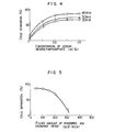
- Fig. 4 is a characteristic figure showing the relation between the concentration of sodium hexamethaphosphate and the separation rate of crud.
- Fig. 5 is a characteristic figure showing the relation between the amount of the powdered ion exchange resin packed and the separation rate of crud.
- Fig. 1 is an illustration showing the adhesion and excoriation of crud to and from the granular ion exchange resin.
- Fig. 2 is an illustration showing the adhesion and excoriation of the crud to and from the powdered ion exchange resin.
- Fig. 3 is a system drawing of an apparatus for
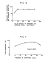
- Fig. 6 is a characteristic figure showing the relation between the amount of the powdered ion exchange resin packed and the recovery rate of the powdered ion exchange resin.
- Fig. 7 is a characteristic figure showing the relation between the frequency of supersonic and the separation rate of crud.
- Fig. 8 is a characteristic figure showing the relation between the temperature of the powdered ion exhcnage resin slurry and the separation rate of crud.
- Fig. 9 is a characteristic figure showing the relation between the length of the irradiation time of supersonic and the separation rate of crud.
- Fig. 10 is a characteristic figure showing the relation between the pH of the slurry adjusted by addition of an acid or an alkali and the separation rate of crud.
- Fig. 11 is a characteristic figure showing the relation between the concentration of sulfuric acid and the separation rate of crud.
- a condensate demineralizer and a condensate demineralizer filter in the water feed pipe feeding cooling water to a pressure vessel of an atomic reactor from a condenser.
- the condensate demineralizer has accumulated layers consisting of the packed granular cation exchange resin and the packed granular anion exchange resin therein. When described simply as granular ion exchange resin, these two ion exchange resins are involved.
- the condensate filter has a filter material obtained by precoating a mixture of the powdered cation exchange resin and the powdered anion exchange resin on a holder.
- the powdered ion exchange resin is a general term of these two powdered ion exchange resins.
- the mean particle diameter of granular ion exchange resin is about 500 ⁇ m and that of the powdered ion exchange resin is about 50 ⁇ m.
- the crud formed in the main steam feeding pipe and in the water feeding pipe in the upstream of the condensate demineralizer filter, of atomic power plant of boiling water type reactor, is removed by means of a condensate demineralizer filter.
- the particle diameter of crud is about 1 to 10 ⁇ m.
- the frequency of reversal washing is generally once per 10 to 15 days and the amount of ion exchange resin per each reversal washing is in the range from 5 to 10 m 3 in the boiling water reactor of electric output of 1100 Mwe.
- the crud formed in the atomic power plant of the boiling water type reactor comprises mainly a-hematite (a-Fe 2 0 3 ).
- An oxide of iron has a strong ion exchanging ability.
- the crud is also apt to adsorb radioactive ions such as co 60 in the cooling water.
- the crud in the cooling water of the atomic power plant is usually positively charged and has a hydrophobic surface characteristic. Hence, the crud adheres rather strongly to the surface of the cation exchange resin whose surface is negatively charged by the static attraction and van der Waals affinity force. Adhesion state of crud to the granular ion exchange resin and the powdered ion exchange resin is shown in Fig. 1(A) and Fig. 2(A), respectively.
- Fig. 1(A) shows the adhesion state of crud by the first phemonenan.
- the numeral 1 is the granular cation exchange resin and the numeral 2 is the crud.
- crud 2 is positively charged, and hence it is likely to be adsorbed to the surface of the granular cation exchange resin 1.
- Crud 2 thus adhered electrically to the surface of the granular ion exchange resin is not separated from the surface of the granular ion exchange resin even by reversal washing of the granular ion exchange resin.
- the crud captured by the second phenomenon so as to occupy the space between the adjacent mutual granular ion exchange resins in the granular ion exchange resin layer can be removed easily by reversal washing.
- the crud is adhered to the granular ion exchange resin by the first phenomenon, the part of the granular ion exchange resin on which the crud is adsorbed is not sufficiently regenerated by chemicals and it is difficult to restore the ion exchanging of said part of the ion exchange resin.
- the numeral 3 is the powdered cation exchange resin
- the numeral 4 is the powdered anion exchange resin. Since the powdered ion exchange resin (particle diameter: 2 to 90 p) has a very small particle diameter as compared with the granular ion exchange resin (particle diameter: 0.25 to 1.2 mm), the powdered cation exchange resin '3 and the powdered anion exchange resin 4 attract mutually and strongly by the static force, thereby forming a block.
- the crud can be separated from the ion exchange resin. But, when application of the supersonic is stopped, the crud separated by the adsorbing force such as electric attraction or the like is again adsorbed on the surface of the ion exchange resin. Therefore, the separation rate of crud adhered to the iron exchange resin is extremely small.
- the separation rate of crud from either one of the granular and the powdered ion exchange resins is about 20%. In the case of the powdered ion exchange resin having a very strong static attraction, the separation rate of crud is further smaller as compared with the granular ion exchange resin.
- a dispersing agent is added according to the present invention.
- the dispersing agent charges the surface of crud either positively or negatively and disperses the crud by taking advantage of the static repellence force formed among the mutual cruds, making it possible to obtain the colloidally stabilized condition.
- Fig. 3 shows an apparatus realizing the process for separating the crud from the ion exchange resin.
- Said crud-separating apparatus 5 consists of crud-separating tank 6, supersonic transmitter 7, crud-precipitating vessel 10 and dispersing agent blending tank 11.
- the supersonic transmitter 7 is provided at the bottom of the crud-separating tank 6.
- Resin feed pipe 13 and resin discharge pipe 16 are - communicated with the crud-separating tank 6.
- Pipe 14 and valve 15 are set on the resin feed pipe 13.
- the resin feed pipe 13 is connected with at least one of the condensate demineralizer and condensate demineralizer filter.
- the demineralizer filter obtained by precoating the powdered ion exchange resin on a:holder is also set in the reactor clean-up system of a boiling water type reactor.
- the resin feed pipe 13 is also connected with this demineralizer filter.
- Valve 17 is installed on the resin discharge pipe 16.
- Pipe 18 having valve 19 communicates the crud-separating tank 6 with blending tank 8.
- Pipe 20 set on the coagulating agent tank 9 is connected with the blending tank 8.
- Valve 21 is set on the pipe 20.
- Stirrer 33 is inserted into the blending tank 8.
- Pipe 22 communicates the blending tank 8 with the crud-precipitating vessel 10.
- Crud-discharge pipe 23 having valve 24 is connected with the crud-precipitating vessel 10.
- Pipe 25 connected with the crud-precipitating vessel 10 is communicated with the dispersing agent blending tank 11.
- Level gauge 29 is set in the dispersing agent blending tank 11.
- One end of pipe 26 in which pump 27 and valve 28 are set is connected with the dispersing agent blending tank 11 and the other end thereof is inserted into the crud-separating tank 6.
- Pipe 30 connects the dipersing agent blending tank 11 with dispersing tank 12. Pump 31 and valve 32 are set in the pipe 30.
- the powdered ion exchange resin discharged by reversal washing with water supplied from the condensate filter is fed to the crud-separating tank 6 through the resin feed pipe 13 in the form of slurry.
- the powdered ion exchange resin is precipitated in the bottom of the crud-separating tank 6.
- Water'containing the dispersing agent for example, a sort of the dispersing agent mentioned above
- present in the dispersing agent blending tank 11 is fed to the crud-separating tank 6 via the pipe 26 by driving the pump 27 and mixed with the slurry of the powered ion exchange resin.
- the supersonic transmitter 7 is operated in such condition to irradiate the supersonic to the powdered ion exchange resin.
- the crud adhering to the powdered ion exchange resin is separated from the powdered ion exchange resin by the action of supersonic.
- the crud separated moves upwards to the top of the crud-separating tank 6 while being irradiated with supersonic.
- the powdered ion exchange resin is present in the bottom of the crud-separating tank 6.
- Such phenomenon occurs even when the feed of all liquids, particularly water from the pipe 26 to the crud-separating tank 6 is stopped. This is because the particle diameter of crud is smaller than that of the powdered ion exchange resin and because the action of the supersonic works.
- the valve 19 When the valve 19 is opened, water containing the crud flows into the blending tank 8 via.the pipe 18.
- the coagulating agent in the coagulating agent tank 9 is fed to the blending tank 8 by opening the valve 21.
- the coagulating agent serves to neutralize the surface charge of crud and weaken the repellence force thereof, and usually polyanionic or nonionic coagulating agent is employed.
- Water containing the coagulating agent and the crud is blended homogeneously by the operation of the stirrer 33. Subsequently, the water is fed to the crud-precipitating tank 10.
- the crud is precipitated in the crud-precipitating tank 10 and accumulated in the bottom of the tank 10. Precipitation of the crud is accelerated by the action of the condensing agent.
- the supernatant water not containing the crud is fed to the dispersing agent blending tank 11.
- the concentration of dispersing agent in the dispersing agent blending tank 11 is measured.
- the pump 31 is rotated to feed the dispersing agent in the dispersing agent tank 12 to the dispersing agent blending tank 11.
- the concentration of the dispersing agent in the dispersing agent blending tank 11 reaches the predetermined level, rotation of the pump 31 is stopped and feed.of the dispersing agent to the dispersing agent blending tank 11 is stopped.
- the pump 27 does not work.
- the crud (adsorbing radioactive ions such as cobalt 60 and the like) which was precipitated in the bottom of the crud-precipitating tank 10 is taken out through the pipe 23 by opening the value 24 and treated as radioactive wastes.
- the powdered ion exchange resin from which the crud was separated, is discharged into the resin discharge pipe 16 from the crud-separating tank 6.
- Fig. 4 shows the characteristics obtained after sodium hexamethaphosphate, one of the chelating agents, was blended as a dispersing agent with the slurry of the powdered ion exchange resin and supersonic of 30 kHz, 45 kHz and 50 kHz in frequency was irradiated to the powdered ion exchange resin. Separation of the crud did not change so much even when the concentration of hexamethaphosphate reached 0.5% by weight or higher.
- Figs. 5 and 6 show the relation between the filled amount of the powdered ion exchange resin based on the water in the crud-separating tank 6 and separation rate of the crud, and the relation between the filled amount of the powdered ion exchange resin and the recovery rate of the powdered ion exchange resin, respectively.
- the dispersing agent there was used a solution containing 0.5% by weight of sodium hexamethaphosphate, and supersonic of 45 kHz in frequency was irradiated.
- Fig. 7 shows the relation between the frequency of the supersonic and the separation rate of crud.
- a solution containing 0.5% by weight of sodium hexamethaphosphate was blended with a slurry of the powdered ion exchange resin and supersonic of output 100 W was irradiated.
- the separation rate of crud was high under the irradiation of supersonic in the range of 30 to 50 kHz in frequency.
- the separation rate of crud decreases markedly when the frequency of the supersonic reaches 50 kHz or more. This is because, when the frequency of the supersonic is too high, the shearing force due to the cavitation generated does not work effectively on the separation of crud.
- Fig. 8 shows the influence of the slurry temperature on the separation rate of crud.
- the separation rate of crud decreases due to the decrease of surface tension of the liquid. It is therefore, desirable to carry out the separation of crud under irradiation of the supersonic at the slurry temperature of 50°C or less.
- a solution of 0.5% by weight of sodium hexamethaphosphate was used as a dispersing agent.
- the charactersitics shown in Figs. 4 to 8 were the results of experiments in which the powdered ion exchange resin comprising mostly styrene-divinyl benzene copolymer was used. Said powdered ion exchange resin had a mean particle diameter of about 10 ⁇ m.
- Example 2 To 20 ml of the same powdered ion exchange resin as shown in Example 1 was added a solution containing 1% by weight of sodium hexamethaphosphate in an amount of 2 times as much and the resulting mixture was allowed to stand under the irradiation of supersonic (power output: 100 W) of 23 kHz in frequency.
- the relation between the length of treating time and the separation rate of crud after separation of the supernatant was shown in Fig. 9. The separation rate of crud remained almost constant in the treating time of 30 minutes or longer.
- the powdered ion exchange resin containing 10% by weight of iron oxide as the crud and having a radioactivity concentration of 0.08 uCi/mt was put into a separating liquid containing about 0.5% by weight of sodium citrate, which is another chelating agent, and having a pH value of 12.
- Supersonic of 23 kHz in frequency was irradiated thereonto.
- the length of time for the supersonic treatment could be selected optionally.
- the separation rate of crud reached as high as about 97% by the treatment for one hour.
- the radioactivity concentration of the dried powdered ion exchange resin was markedly reduced to 0.03 ⁇ Ci/ml.
- Fig. 10 shows the characteristics obtained when sulfuric acid was blended as a dispersing agent with a slurry of the ion exchange resin and supersonic of 45 kHz in frequency was irradiated thereonto.
- the separation rate was about 20% and, when the pH value was 2, the separation rate was about 40%.
- the pH value was 1, there was obtained the separation rate of about 80%.
- the repellent force overcoming the readhesion force is obtained only when the pH value is 2 or less, desirably 1 or less. From the view-point of increasing the repellent force due to the surface charge, negatively charging by the addition of alkali is possible.
- addition of sodium hydroxide up to the pH vlaue of 13 or 14 affords the separation rate of only about 40% and it has been confirmed that the efficiency of this method is low.
- Sulfuric.acid was used as a dispersing agent in this Example.
- To a slurry of the powdered ion exchange resin shown in Example 1 was added diluted sulfuric acid and admixed therewith, and supersonic of 45 kHz in frequency was irradiated thereonto.
- the relation between the concentration of sulfuric acid and separation rate of crud was shown in Fig. 11. In case that the concentration of sulfuric acid was 0.1 N or less, the separation rate of crud was markdly reduced.
- the ion exchange resin from which the crud was removed is the reuse as an ion exchange resin.
- a chelating agent used as a dispersing agent
- the ion exchange resin has no ion exchanging ability when the crud is removed, because the ion exchange resin has absorbed the chelating agent. Therefore, first of all, the ion exchange resin is separated into the anion exchange resin and the cation exchange resin.
- the anion exchange resin and the cation exchange resin are washed with sodium hydroxide and sulfuric acid, respectively. These washing liquids are discarded as radioactive wastes but they are low in radioactivity because they do not contain the crud.
- the ion exchange resin from which the crude has been removed is the use as a precoating material on the precoat type filters including the condensate demineralizer filter.
- the ion exchange resin, particularly the cation exchange resin, from which the crud has been removed is used as a precoating material on the holder of a condensate demineralizer filter because of the remaining ion exchanging ability thereof and its ion exchanging ability is utilized.
- the ion exchange resin is used as a precoating material for the precoat type filter which is provided in the radioactive waste disposal system, for example, machinery drain disposal system of a power plant.
- the initial differential pressure of the filter was 0.2 kg/cm 2 , which was capable of removing the crud (iron oxide of 3 ⁇ m in average particle diameter) favorably, the removal rate of crud being as high as 99%.
- the powdered ion exchange resin is difficult in separating the cation exchange resin from the anion exchange resin, as compared with the granular ion exchange resin, and hence regneration thereof is extremely difficult. Consequently, use of the powdered ion exchange resin as a precoating material is very significant.
- the above mentioned use of the powdered ion exchange resin does not generate the powdered ion exchange resin which becomes radioactive wastes and contributes to the reduction of the amount of radioactive wastes.
- the ion exchange resin When the ion exchange resin is to be discarded, removal of crud is beneficial. When the radioactive wastes are stored in a container, it is required that the dosage of the container surface be 200 mRe/H or less. In contrast, when it is intended to discard the used ion exchange resin without the removal of crud, the radioactivity concentration of the ion exchange resin reaches 0.1 ⁇ Ci/ml and hence only about 20 kg is allowed to be contained in a drum of 200 t capacity when canned by the known cement-solidification method.
- the radioactivity concentration of the ion exchange resin is reduced to 0.05 ⁇ Ci/ml and hence it is possible to hold the dosage of the drum surface under the standard level or less even when about 40 kg of the ion exchange resin is packed in a drum of 200 t capacity. This effect results in the reduction of the number of drums for radioactive wastes.
Landscapes
- Chemical & Material Sciences (AREA)
- Organic Chemistry (AREA)
- Chemical Kinetics & Catalysis (AREA)
- Treatment Of Water By Ion Exchange (AREA)
Applications Claiming Priority (4)
| Application Number | Priority Date | Filing Date | Title |
|---|---|---|---|
| JP55153358A JPS5775151A (en) | 1980-10-30 | 1980-10-30 | Separation of component stuck on ion exchange resin |
| JP153358/80 | 1980-10-30 | ||
| JP172036/80 | 1980-12-08 | ||
| JP55172036A JPS6013752B2 (ja) | 1980-12-08 | 1980-12-08 | 粉状イオン交換樹脂の再使用方法 |
Publications (2)
| Publication Number | Publication Date |
|---|---|
| EP0052453A1 true EP0052453A1 (fr) | 1982-05-26 |
| EP0052453B1 EP0052453B1 (fr) | 1985-04-17 |
Family
ID=26482005
Family Applications (1)
| Application Number | Title | Priority Date | Filing Date |
|---|---|---|---|
| EP81305135A Expired EP0052453B1 (fr) | 1980-10-30 | 1981-10-29 | Procédé pour enlever des dépots de résines échangeuses d'ions |
Country Status (3)
| Country | Link |
|---|---|
| US (1) | US4389253A (fr) |
| EP (1) | EP0052453B1 (fr) |
| DE (1) | DE3170026D1 (fr) |
Cited By (5)
| Publication number | Priority date | Publication date | Assignee | Title |
|---|---|---|---|---|
| FR2536678A1 (fr) * | 1982-07-29 | 1984-06-01 | Nalco Chemical Co | |
| EP0484984A1 (fr) * | 1990-11-09 | 1992-05-13 | Ebara Corporation | Méthode de filtration et de déminérisation à l'aide d'un lit mixte d'échangeurs d'ions |
| US5387348A (en) * | 1990-11-09 | 1995-02-07 | Ebara Corporation | Method of mixed-bed filtration and demineralization with ion-exchange resins |
| WO1997040938A1 (fr) * | 1996-04-25 | 1997-11-06 | Aquasonic Trust, Reg. | Procede et dispositif pour traiter et modifier un materiau d'echange ionique, ainsi que pour ameliorer le caractere ecophile des processus d'echange ionique |
| CN107240432A (zh) * | 2017-05-18 | 2017-10-10 | 重集团大连工程技术有限公司 | 一种核电厂放射性废液处理工艺方法 |
Families Citing this family (13)
| Publication number | Priority date | Publication date | Assignee | Title |
|---|---|---|---|---|
| US4437999A (en) * | 1981-08-31 | 1984-03-20 | Gram Research & Development Co. | Method of treating contaminated insoluble organic solid material |
| US4770790A (en) * | 1983-06-17 | 1988-09-13 | Nalco Chemical Company | Treatment and prevention of fouled water treatment solids |
| US4615984A (en) * | 1984-02-23 | 1986-10-07 | Becton Dickinson & Company | Dissociation of ligand-binder complex using ultrasound |
| US5665239A (en) * | 1996-01-16 | 1997-09-09 | Culligan International Company | Processes for deionization and demineralization of fluids |
| DE10126869A1 (de) * | 2001-06-01 | 2002-12-19 | Saint Gobain Sekurit D Gmbh | Elektrisch beheizbare Scheibe |
| AU2005248963A1 (en) * | 2005-05-24 | 2006-12-14 | Ashland Licensing And Intellectual Property Llc | Process for reducing contaminants in condensate resulting from the conversion of bauxite to alumina |
| US20060278358A1 (en) * | 2005-06-02 | 2006-12-14 | Hildebrand Lynn N | Process for reducing contaminants in condensate resulting from the conversion of bauxite to alumina |
| US7517448B2 (en) * | 2005-07-28 | 2009-04-14 | Chen Tony C T | Recycling cool water filter |
| US20070080114A1 (en) * | 2005-09-09 | 2007-04-12 | Dewitt-Dick Douglas B | Process for reducing contaminants in condensate resulting from the conversion of bauxite to alumina |
| WO2011152909A2 (fr) | 2010-03-09 | 2011-12-08 | Kurion, Inc. | Séparation et vitrification spécifiques d'isotopes au moyen de milieux spécifiques d'ions |
| WO2012048116A2 (fr) * | 2010-10-06 | 2012-04-12 | Electric Power Research Institute Inc. | Régénération d'échange d'ions et procédés sélectifs pour un nucléide spécifique |
| WO2013191781A2 (fr) * | 2012-03-26 | 2013-12-27 | Kurion, Inc. | Régénération sélective de résines de milieux spécifiques à un isotope dans des systèmes pour séparation d'isotopes radioactifs de matières de déchets liquides |
| RU2631942C1 (ru) * | 2016-09-22 | 2017-09-29 | Общество с ограниченной ответственностью Научно-производственное предприятие "Эксорб" | Способ дезактивации радиоактивных ионообменных смол |
Citations (5)
| Publication number | Priority date | Publication date | Assignee | Title |
|---|---|---|---|---|
| FR906825A (fr) * | 1942-10-02 | 1946-02-21 | Ig Farbenindustrie Ag | Procédé pour débarrasser les substances à action d'échange des impuretés qui les encrassent |
| FR1184272A (fr) * | 1957-10-12 | 1959-07-20 | Procédé pour éliminer les matières organiques retenues sur des échangeurs d'ions | |
| US2977313A (en) * | 1956-05-22 | 1961-03-28 | Hagan Chemicals & Controls Inc | Method of cleansing, sterilizing, and preventing corrosion in base exchange and cation exchange systems and products used therein |
| GB977112A (en) * | 1960-03-03 | 1964-12-02 | Rohm & Haas | Removal of iron oxide |
| US3822055A (en) * | 1970-05-20 | 1974-07-02 | Gen Electric | Ultrasonic cleaning of resin |
Family Cites Families (12)
| Publication number | Priority date | Publication date | Assignee | Title |
|---|---|---|---|---|
| NL78480C (fr) * | 1950-11-16 | |||
| US2683695A (en) * | 1952-06-27 | 1954-07-13 | Barnstead Still And Sterilizer | Regeneration of cation exchangers containing alkaline earth metals |
| US3663163A (en) * | 1970-05-18 | 1972-05-16 | Us Interior | Regeneration of cation exchange resins and recovery of salts |
| US3849196A (en) * | 1970-05-20 | 1974-11-19 | Gen Electric | Ultrasonic cleaning of resin |
| US3882018A (en) * | 1970-12-04 | 1975-05-06 | Aerojet General Co | Process for recovery of minerals from acidic streams |
| US3700592A (en) * | 1970-12-04 | 1972-10-24 | Aerojet General Co | Process for the removal and recovery of mineral pollutants from water |
| CA1031084A (fr) * | 1973-03-12 | 1978-05-09 | Robert Kunin | Methode de traitement de l'eau |
| US3977968A (en) * | 1973-04-13 | 1976-08-31 | Nalco Chemical Company | Ion exchange regeneration |
| US3941693A (en) * | 1974-08-12 | 1976-03-02 | Aerojet-General Corporation | Solid mineral and regenerant recovery for ion-exchange resins |
| DE2524172A1 (de) * | 1975-05-31 | 1976-12-16 | Giulini Gmbh Geb | Verbessertes verfahren zur wasser-, abwasser- und schlammbehandlung mit flockungsmitteln |
| US4080418A (en) * | 1977-02-22 | 1978-03-21 | Amax Inc. | Extraction of cobalt, copper and nickel values from ammoniacal solutions with chelating exchange resins of restored capacity |
| US4205966A (en) * | 1978-11-02 | 1980-06-03 | Fuji Photo Film Co., Ltd. | System for ultrasonic wave type bubble removal |
-
1981
- 1981-10-28 US US06/315,736 patent/US4389253A/en not_active Expired - Fee Related
- 1981-10-29 DE DE8181305135T patent/DE3170026D1/de not_active Expired
- 1981-10-29 EP EP81305135A patent/EP0052453B1/fr not_active Expired
Patent Citations (5)
| Publication number | Priority date | Publication date | Assignee | Title |
|---|---|---|---|---|
| FR906825A (fr) * | 1942-10-02 | 1946-02-21 | Ig Farbenindustrie Ag | Procédé pour débarrasser les substances à action d'échange des impuretés qui les encrassent |
| US2977313A (en) * | 1956-05-22 | 1961-03-28 | Hagan Chemicals & Controls Inc | Method of cleansing, sterilizing, and preventing corrosion in base exchange and cation exchange systems and products used therein |
| FR1184272A (fr) * | 1957-10-12 | 1959-07-20 | Procédé pour éliminer les matières organiques retenues sur des échangeurs d'ions | |
| GB977112A (en) * | 1960-03-03 | 1964-12-02 | Rohm & Haas | Removal of iron oxide |
| US3822055A (en) * | 1970-05-20 | 1974-07-02 | Gen Electric | Ultrasonic cleaning of resin |
Non-Patent Citations (2)
| Title |
|---|
| CHEMICAL ABSTRACTS, Vol. 85, No. 14, 4th October 1976, page 48, No. 95321x Colu mbus, Ohio, U.S.A. L. M. BLYANKMAN et al.: " Ultrasonic Process for Regeneration of the Exchange Capacity of Ion Exchangers " & Teploenergetika (Moskow) 1976, (4), 74-78 * Abstract * * |
| CHEMICAL ABSTRACTS, Vol. 85, No. 20, 15. November 1976, page 400, No. 148873n Columbus, Ohio, U.S.A. L. M. BLYANKMAN et al.: " Removal of Iron from Condensate on Granular Filtration Materials treated by Ultrasound " & Probl. Okhr. Prir. Ispol'z. Stochnykh Vod 1974, 68-75 * Abstract * * |
Cited By (6)
| Publication number | Priority date | Publication date | Assignee | Title |
|---|---|---|---|---|
| FR2536678A1 (fr) * | 1982-07-29 | 1984-06-01 | Nalco Chemical Co | |
| EP0484984A1 (fr) * | 1990-11-09 | 1992-05-13 | Ebara Corporation | Méthode de filtration et de déminérisation à l'aide d'un lit mixte d'échangeurs d'ions |
| US5387348A (en) * | 1990-11-09 | 1995-02-07 | Ebara Corporation | Method of mixed-bed filtration and demineralization with ion-exchange resins |
| WO1997040938A1 (fr) * | 1996-04-25 | 1997-11-06 | Aquasonic Trust, Reg. | Procede et dispositif pour traiter et modifier un materiau d'echange ionique, ainsi que pour ameliorer le caractere ecophile des processus d'echange ionique |
| CN107240432A (zh) * | 2017-05-18 | 2017-10-10 | 重集团大连工程技术有限公司 | 一种核电厂放射性废液处理工艺方法 |
| CN107240432B (zh) * | 2017-05-18 | 2019-02-22 | 一重集团大连工程技术有限公司 | 一种核电厂放射性废液处理工艺方法 |
Also Published As
| Publication number | Publication date |
|---|---|
| US4389253A (en) | 1983-06-21 |
| EP0052453B1 (fr) | 1985-04-17 |
| DE3170026D1 (en) | 1985-05-23 |
Similar Documents
| Publication | Publication Date | Title |
|---|---|---|
| US4389253A (en) | Process for removing crud from ion exchange resin | |
| JP6173396B2 (ja) | 原発の重大事故時に発生する放射性廃液の処理方法及び処理装置 | |
| EP0441478A1 (fr) | Méthode de séparation | |
| EP0198717B1 (fr) | Méthode de traitement des déchets radioactifs | |
| JPS6136198B2 (fr) | ||
| US4524153A (en) | Method of and system for regenerating powdery ion-exchange resin | |
| JP3119538B2 (ja) | 放射性廃樹脂の除染方法 | |
| JP3388920B2 (ja) | 発電所の廃液処理方法およびその装置 | |
| US4415457A (en) | Process for treating liquid waste containing solid fine particles | |
| Roberts | A phenolic resin ion exchange process for decontaminating low-radioactivity-level process water wastes | |
| Brooksbank et al. | LOW-RADIOACTIVITY-LEVEL WASTE TREATMENT. PART II. PILOT PLANT DEMONSTRATION OF THE REMOVAL OF ACTIVITY FROM LOW-LEVEL PROCESS WASTES BY A SCAVENGING-PRECIPITATION ION-EXCHANGE PROCESS | |
| US3137634A (en) | Nuclear reactor operation | |
| JP2025070750A (ja) | 放射性廃液処理装置 | |
| Harjula et al. | Pilot scale testing of inorganic ion exchangers for precoat applications | |
| US5564103A (en) | Reducing the volume of depleted ion exchange bead resin | |
| KR830001693B1 (ko) | 방류액의 방사능 제거 처리방법 | |
| JPS6013752B2 (ja) | 粉状イオン交換樹脂の再使用方法 | |
| JPH0138554B2 (fr) | ||
| JPS59145012A (ja) | 微粒子懸濁液の濾過方法 | |
| JPS6125686A (ja) | 復水浄化法 | |
| JPS59138992A (ja) | 復水浄化装置 | |
| JPS59136141A (ja) | 復水脱塩装置のイオン交換樹脂再生方法 | |
| JPS58201096A (ja) | 復水脱塩装置 | |
| JPH0420156B2 (fr) | ||
| RU2553976C1 (ru) | Способ очистки от 60co технологических растворов радиохимического производства, относящихся к средне- и низкоактивным отходам |
Legal Events
| Date | Code | Title | Description |
|---|---|---|---|
| PUAI | Public reference made under article 153(3) epc to a published international application that has entered the european phase |
Free format text: ORIGINAL CODE: 0009012 |
|
| AK | Designated contracting states |
Designated state(s): DE FR SE |
|
| RBV | Designated contracting states (corrected) |
Designated state(s): DE FR SE |
|
| 17P | Request for examination filed |
Effective date: 19820930 |
|
| GRAA | (expected) grant |
Free format text: ORIGINAL CODE: 0009210 |
|
| AK | Designated contracting states |
Designated state(s): DE FR SE |
|
| REF | Corresponds to: |
Ref document number: 3170026 Country of ref document: DE Date of ref document: 19850523 |
|
| ET | Fr: translation filed | ||
| PLBE | No opposition filed within time limit |
Free format text: ORIGINAL CODE: 0009261 |
|
| STAA | Information on the status of an ep patent application or granted ep patent |
Free format text: STATUS: NO OPPOSITION FILED WITHIN TIME LIMIT |
|
| 26N | No opposition filed | ||
| PGFP | Annual fee paid to national office [announced via postgrant information from national office to epo] |
Ref country code: SE Payment date: 19930907 Year of fee payment: 13 |
|
| PGFP | Annual fee paid to national office [announced via postgrant information from national office to epo] |
Ref country code: FR Payment date: 19930914 Year of fee payment: 13 |
|
| PGFP | Annual fee paid to national office [announced via postgrant information from national office to epo] |
Ref country code: DE Payment date: 19931231 Year of fee payment: 13 |
|
| PG25 | Lapsed in a contracting state [announced via postgrant information from national office to epo] |
Ref country code: SE Effective date: 19941030 |
|
| EAL | Se: european patent in force in sweden |
Ref document number: 81305135.6 |
|
| PG25 | Lapsed in a contracting state [announced via postgrant information from national office to epo] |
Ref country code: FR Effective date: 19950630 |
|
| PG25 | Lapsed in a contracting state [announced via postgrant information from national office to epo] |
Ref country code: DE Effective date: 19950701 |
|
| EUG | Se: european patent has lapsed |
Ref document number: 81305135.6 |
|
| REG | Reference to a national code |
Ref country code: FR Ref legal event code: ST |