EP0052458B1 - Einrichtung zum Verteilen von Pulver - Google Patents
Einrichtung zum Verteilen von Pulver Download PDFInfo
- Publication number
- EP0052458B1 EP0052458B1 EP81305180A EP81305180A EP0052458B1 EP 0052458 B1 EP0052458 B1 EP 0052458B1 EP 81305180 A EP81305180 A EP 81305180A EP 81305180 A EP81305180 A EP 81305180A EP 0052458 B1 EP0052458 B1 EP 0052458B1
- Authority
- EP
- European Patent Office
- Prior art keywords
- receptacle
- assembly
- extending
- stud shaft
- bar
- Prior art date
- Legal status (The legal status is an assumption and is not a legal conclusion. Google has not performed a legal analysis and makes no representation as to the accuracy of the status listed.)
- Expired
Links
- 239000000843 powder Substances 0.000 title claims abstract description 36
- 239000002245 particle Substances 0.000 claims abstract description 33
- 210000001364 upper extremity Anatomy 0.000 claims abstract description 9
- 210000003141 lower extremity Anatomy 0.000 claims abstract description 3
- 230000000712 assembly Effects 0.000 description 4
- 238000000429 assembly Methods 0.000 description 4
- 239000004464 cereal grain Substances 0.000 description 2
- 239000002923 metal particle Substances 0.000 description 2
- 235000013339 cereals Nutrition 0.000 description 1
- 239000000428 dust Substances 0.000 description 1
- 210000003414 extremity Anatomy 0.000 description 1
- 239000012535 impurity Substances 0.000 description 1
- 230000010355 oscillation Effects 0.000 description 1
- 239000007787 solid Substances 0.000 description 1
Images

Classifications
-
- B—PERFORMING OPERATIONS; TRANSPORTING
- B65—CONVEYING; PACKING; STORING; HANDLING THIN OR FILAMENTARY MATERIAL
- B65G—TRANSPORT OR STORAGE DEVICES, e.g. CONVEYORS FOR LOADING OR TIPPING, SHOP CONVEYOR SYSTEMS OR PNEUMATIC TUBE CONVEYORS
- B65G47/00—Article or material-handling devices associated with conveyors; Methods employing such devices
- B65G47/02—Devices for feeding articles or materials to conveyors
- B65G47/16—Devices for feeding articles or materials to conveyors for feeding materials in bulk
- B65G47/18—Arrangements or applications of hoppers or chutes
-
- B—PERFORMING OPERATIONS; TRANSPORTING
- B07—SEPARATING SOLIDS FROM SOLIDS; SORTING
- B07B—SEPARATING SOLIDS FROM SOLIDS BY SIEVING, SCREENING, SIFTING OR BY USING GAS CURRENTS; SEPARATING BY OTHER DRY METHODS APPLICABLE TO BULK MATERIAL, e.g. LOOSE ARTICLES FIT TO BE HANDLED LIKE BULK MATERIAL
- B07B11/00—Arrangement of accessories in apparatus for separating solids from solids using gas currents
- B07B11/06—Feeding or discharging arrangements
Definitions
- the powder dispensing assembly of the subject invention is utilized to dispense a curtain of falling powder particles at a controlled and precise rate.
- the subject invention is particularly suitable for use in the processing of powder metal particles.
- the powder particles are frequently classified according to size.
- One manner in which this is accomplished is to establish a curtain of falling powder particles which fall into a horizontally moving stream of gas which establishes short trajectories for the heavier powder particles and long trajectories for the lighter powder particles so that the powder particles fall into classification compartments.
- the subject invention is particularly useful for dispensing such a curtain of falling powder particles.
- FR-A-1192015 discloses a cleaner/separator device according to the preamble of claim 1 for freeing cereal grains from dust and light impurities by the action of a current of air.
- the cereal grains are stored in a hopper, the bottom of which is formed by the separate, downwardly inclined, plate having a lip over which the grains pass.
- An adjustable flap connected to the hopper varies the gap between the hopper wall and the bottom plate, and the latter may be connected to the oscillation means present with associated sieves to move the plate forward and backwards. While this apparatus may be suitable for the purpose intended, the fact that the flow control flap does not oscillate with the plate makes it unsuitable for powder dispensing applications.
- a powder dispensing assembly constructed in accordance with the subject invention comprises support structure with dispensing means movably supported by the support structure for receiving powder and having a lip over which particles of powder move to define a falling curtain of powder particles and supply means for establishing a flow path and supplying powder particles to the dispensing means.
- the dispensing means defines an elongated receptacle for receiving powder particles from the supply means with the receptacle having a rear wall and a bottom wall extending from the rear wall to the lip and end walls at opposite ends of the bottom and rear walls.
- the receptacle includes flow control means extending between the end walls above the bottom wall to establish a gap between the bottom wall and the flow control means and drive means for vibrating the receptacle rectilinearly and parallel to the lip so that the walls and flow control means vibrate in unison to dispense particles through the gap and over the lip.
- the dispensing means also includes an adjustment means for adjusting the angular position of the receptacle relative to the support structure about its longitudinal axis extending between said end walls thereof.
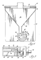
- a powder dispensing assembly constructed in accordance with the subject invention is generally shown at 10.
- the assembly 10 includes a support structure defined by first and second spaced end plates 12 and 14 and a top plate 16 extending between the top or upper extremities of the end plates 12 and 14.
- the end plates 12 and 14 are connected to the ends of the top plate 16 by bolts 17 which threadedly engage the ends of the top plate 16.
- a plurality of tubes are secured to the top plate 16 to define inlet openings for passing articles therethrough.
- the assembly 10 also includes dispensing means generally indicated at 18 and movably supported by the end plates 12 and 14 of the support structure for receiving powder and having or defining a lip 20 over which particles of powder move to define a falling curtain of powder particles.
- the dispensing means 18 is defined by an elongated cylindrical receptacle for receiving powder particles from the supply means 22.
- the cylindrical receptacle defines a rear wall 30 and a bottom wall 32 extending forwardly from the rear wall 30 to the lip 20 with end walls 34 at opposite ends of the bottom and rear walls 30 and 32.
- the dispensing means 18 defined by the cylindrical receptacle includes flow control means defined by the bar 36 extending between the end walls 34 above the bottom wall 32 to establish a gap between the bottom wall 32 and the bar 36 of the flow control means.
- the assembly 10 also includes a drive means including the rod 38 and a vibrator or oscillator 40 shown in phantom in FIGURE 1 for vibrating the receptacle defining the dispensing means 18 rectilinearly and in a direction parallel to the lip 20 so that the walls 30, 32 and 34 and the bar 36 of the flow control means vibrate in unison to dispense particles through the gap and over the lip 20.
- a drive means including the rod 38 and a vibrator or oscillator 40 shown in phantom in FIGURE 1 for vibrating the receptacle defining the dispensing means 18 rectilinearly and in a direction parallel to the lip 20 so that the walls 30, 32 and 34 and the bar 36 of the flow control means vibrate in unison to dispense particles through the gap and over the lip 20.
- the bar 36 defining the flow control means is elongated and has a bottom surface 42 defining the upper extremity of the gap and a back surface 44 spaced from the rear wall 30 of the receptacle and, in addition, spaced toward the rear wall 30 of the receptacle from the lip 20.
- the back surface 44 of the bar 36 is spaced rearwardly of the lip 20 and although the back surface 44 is closer to the lip 20 than it is to the rear wall 30, it is closer to the mid point between the lip 20 and the rear wall 30 than it is to the lip 20.
- the second end of the receptacle 18 includes a second recess 50, as shown in FIGURE 2, extending thereinto and opening through the second or other end wall 34.
- the elongated bar 36 has a first end disposed in the first recess 48 and a second end disposed in the second recess 50 and threaded fasteners 52 extend through each end of the bar 36 and threadedly engage the ends of the receptacle in the respective recesses 48 and 50.
- the horizontal or fore and aft position of the bar 36 may be adjusted to change the distance the back surface 44 is positioned from the lip 20. ⁇ Of course, other suitable means may be employed to adjust the position of the bar 36.
- the spaced end plates 12 and 14 of the support structure are adjacent the ends of the receptacle 18.
- a first stud shaft assembly 54 interconnects the first end plate 12 and the first end of the receptacle 18.
- the first stud shaft assembly 54 includes a first stud shaft 58 extending from the first end plate 12 and into a first cavity 60 in the first end of the receptacle 18.
- a first wiper ring 62 is disposed in an annular groove in the cavity 60 and engages the first stud shaft 58 for interconnecting the receptacle 18 and the first stud shaft 58.
- the stud shaft assembly 54 comprises a threaded portion threadedly engaging the end plate 12 and an end portion which may be engaged by an appropriate wrench for rotating the assembly 54.
- the stud shaft 58 extends from the threaded portion of the assembly.
- the rod 38 extends through the first stud shaft assembly 54 to a threaded connection 64 with the first end of the receptacle 18 for moving the receptacle 18 relative to the plates 12, 14 and 16 of the support structure.
- the stud shaft assembly 54 has a cylindrical passage therethrough through which the rod 38 extends and an O-ring is disposed between the interior of the stud shaft portion 58 and the rod 38.
- The-outward end of the rod 38 is also threaded for engaging an appropriate vibrator 40.
- the second stud shaft assembly 56 includes a second stud shaft 66 extending from the second end plate 14 and into a second cavity 68 in the second end of the receptacle 18. Second wiper ring 70 is disposed in the second cavity 68 and engages the second stud shaft portion 66 for interconnecting the receptacle 18 and the second stud shaft 66.
- the stud shaft assembly 56 is a solid fitting member having a threaded portion threadedly engaging the end plate 14 and a head portion for being engaged by an appropriate wrench.
- the assembly 10 also includes an adjustment means for adjusting the angular position of the receptacle 18 about its longitudinal axis extending between the end walls 34 thereof. More specifically, the longitudinal axis extends axially through the stud shafts 58 and 66 whereby the receptacle 18 may be rotated angularly about the axis which extends centrally through the shafts 58 and 66.
- the adjustment means includes a lever arm 72 extending radially from the rod 38 on the outside or opposite side of the end plate 12 from the receptacle 18. The lever 72 may be secured to the rod 38 by an appropriate clamping portion 74.
- An adjustment screw 76 is threadedly supported by the first end plate 12 by a bracket or arm extending therefrom and engages the lever 72 to adjust the position of the lever to rotate the receptacle 18 angularly about the first and second stud shafts 58 and 66.
- biasing means comprising a spring 78 for urging the lever 72 against the adjustment screw 76.
- the spring 78 extends from an arm or lever extending from the end plate 12 to the upper extremity of the lever 72.
- the rod 38 has a notch 80 in the threaded portion 64 thereof which threadedly engages the receptacle 18 with the notch 80 disposed about the first end of the bar 36 for preventing rotation of the rod 38 relative to the receptacle 18.
- the rod 38 may be rotated and, because of the notch 80, the receptacle 18 would be rotated about the axis of its support through the shafts 58 and 66. This adjustment affects the particle flow over the lip 20.
Landscapes
- Engineering & Computer Science (AREA)
- Mechanical Engineering (AREA)
- Filling Or Emptying Of Bunkers, Hoppers, And Tanks (AREA)
- Combined Means For Separation Of Solids (AREA)
- Pens And Brushes (AREA)
- Basic Packing Technique (AREA)
Claims (9)
Priority Applications (1)
| Application Number | Priority Date | Filing Date | Title |
|---|---|---|---|
| AT81305180T ATE24423T1 (de) | 1980-11-14 | 1981-10-30 | Einrichtung zum verteilen von pulver. |
Applications Claiming Priority (2)
| Application Number | Priority Date | Filing Date | Title |
|---|---|---|---|
| US06/207,017 US4359175A (en) | 1980-11-14 | 1980-11-14 | Adjustable vibrating powder dispensing assembly |
| US207017 | 1994-03-04 |
Publications (3)
| Publication Number | Publication Date |
|---|---|
| EP0052458A2 EP0052458A2 (de) | 1982-05-26 |
| EP0052458A3 EP0052458A3 (en) | 1982-08-04 |
| EP0052458B1 true EP0052458B1 (de) | 1986-12-30 |
Family
ID=22768875
Family Applications (1)
| Application Number | Title | Priority Date | Filing Date |
|---|---|---|---|
| EP81305180A Expired EP0052458B1 (de) | 1980-11-14 | 1981-10-30 | Einrichtung zum Verteilen von Pulver |
Country Status (6)
| Country | Link |
|---|---|
| US (1) | US4359175A (de) |
| EP (1) | EP0052458B1 (de) |
| JP (1) | JPS6034916B2 (de) |
| AT (1) | ATE24423T1 (de) |
| CA (1) | CA1168634A (de) |
| DE (1) | DE3175744D1 (de) |
Families Citing this family (9)
| Publication number | Priority date | Publication date | Assignee | Title |
|---|---|---|---|---|
| CA1304544C (en) * | 1987-04-30 | 1992-07-07 | James Dyson | Powder dispensing and cleaning apparatus |
| US4953643A (en) * | 1989-03-06 | 1990-09-04 | Ellion Dolores D | Powder dispensing and measuring device |
| US5341963A (en) * | 1993-01-27 | 1994-08-30 | Horiba Instruments, Inc. | Apparatus for dispensing dry particles |
| DE4407789A1 (de) * | 1994-03-09 | 1995-09-14 | Hauni Werke Koerber & Co Kg | Schwingförderrinne zum Transportieren von Schüttgut, insbesondere Tabak |
| US5897826A (en) | 1996-06-14 | 1999-04-27 | Materials Innovation, Inc. | Pulsed pressurized powder feed system and method for uniform particulate material delivery |
| US5885625A (en) * | 1996-06-14 | 1999-03-23 | Materials Innovation, Inc. | Pressurized feed shoe apparatus for precompacting powdered materials |
| US5885496A (en) * | 1996-08-29 | 1999-03-23 | Materials Innovation, Inc. | Pressurized feedshoe apparatus and method for precompacting powdered materials |
| US6382470B1 (en) | 2000-03-30 | 2002-05-07 | Nestec S.A. | Apparatus for delivering powder in a food dispenser system |
| US10407254B2 (en) * | 2016-04-18 | 2019-09-10 | Harper Industries, Inc. | Pelletized feed distributor |
Citations (1)
| Publication number | Priority date | Publication date | Assignee | Title |
|---|---|---|---|---|
| US949400A (en) * | 1907-06-10 | 1910-02-15 | James M Mcafee | Feed device for roller-mills. |
Family Cites Families (8)
| Publication number | Priority date | Publication date | Assignee | Title |
|---|---|---|---|---|
| GB164171A (en) * | 1920-03-19 | 1921-06-09 | John Manly Walker | Improvements in bins or chutes for granular or pulverulent material |
| DE351873C (de) * | 1921-06-05 | 1922-04-15 | Fried Krupp Akt Ges | Aufgabevorrichtung fuer die Aufbereitungstechnik |
| US2533331A (en) * | 1945-03-01 | 1950-12-12 | Linde Air Prod Co | Powder dispensing |
| FR1192015A (fr) * | 1958-02-27 | 1959-10-23 | Tripette & Renaud | Perfectionnements aux distributeurs des nettoyeurs-séparateurs pour produits granuleux |
| US3058621A (en) * | 1959-09-14 | 1962-10-16 | Blaw Knox Co | Ladle feeding means |
| US3297203A (en) * | 1965-04-26 | 1967-01-10 | Eugene A Wahl | Material feeder |
| US3568894A (en) * | 1969-01-21 | 1971-03-09 | Harper Inc Allen | Means to meter granular or particulate material |
| US3972449A (en) * | 1975-08-13 | 1976-08-03 | Aeonic Press Company | Power feeding apparatus |
-
1980
- 1980-11-14 US US06/207,017 patent/US4359175A/en not_active Expired - Lifetime
-
1981
- 1981-08-05 CA CA000383219A patent/CA1168634A/en not_active Expired
- 1981-09-08 JP JP56141602A patent/JPS6034916B2/ja not_active Expired
- 1981-10-30 AT AT81305180T patent/ATE24423T1/de not_active IP Right Cessation
- 1981-10-30 DE DE8181305180T patent/DE3175744D1/de not_active Expired
- 1981-10-30 EP EP81305180A patent/EP0052458B1/de not_active Expired
Patent Citations (1)
| Publication number | Priority date | Publication date | Assignee | Title |
|---|---|---|---|---|
| US949400A (en) * | 1907-06-10 | 1910-02-15 | James M Mcafee | Feed device for roller-mills. |
Also Published As
| Publication number | Publication date |
|---|---|
| EP0052458A2 (de) | 1982-05-26 |
| JPS6034916B2 (ja) | 1985-08-12 |
| DE3175744D1 (en) | 1987-02-05 |
| JPS57119881A (en) | 1982-07-26 |
| US4359175A (en) | 1982-11-16 |
| ATE24423T1 (de) | 1987-01-15 |
| CA1168634A (en) | 1984-06-05 |
| EP0052458A3 (en) | 1982-08-04 |
Similar Documents
| Publication | Publication Date | Title |
|---|---|---|
| EP0052458B1 (de) | Einrichtung zum Verteilen von Pulver | |
| CN105268641A (zh) | 粮食风选振动筛 | |
| US5791493A (en) | Polysilicon particle classifying apparatus | |
| US4809880A (en) | Dispenser for fungible goods | |
| CN111908173B (zh) | 振动送料装置 | |
| US5080235A (en) | Small particle separator | |
| CA1291967C (en) | Particle feeding apparatus | |
| JP2004181442A (ja) | 粉粒体の振動気流分級純化装置 | |
| JP5835008B2 (ja) | 粉体供給装置 | |
| US4450983A (en) | Powder dispensing assembly | |
| CN106269513A (zh) | 粮食风选振动筛 | |
| RU2132754C1 (ru) | Устройство для сепарации сыпучей смеси | |
| US4304661A (en) | Machines for concentrating ore | |
| US4298168A (en) | Powder dispensing assembly | |
| SU1510959A1 (ru) | Способ сепарации сыпучих смесей | |
| US3667601A (en) | Apparatus for the dry separation of granular materials | |
| RU2241551C2 (ru) | Воздушный камерный сепаратор | |
| US4278537A (en) | Apparatus for separating heavy solids and light solids from a mixture thereof | |
| CN111701872A (zh) | 一种色选机布料机构 | |
| US4421148A (en) | Device for feeding particulate material | |
| GB2078552A (en) | Separators for Separating Granular Material | |
| RU2362634C1 (ru) | Пневматический сепаратор для фракционного разделения и очистки зерна | |
| JPH08238457A (ja) | 気流分級方法および気流分級装置 | |
| JPH0574681U (ja) | 多段分級機 | |
| CN219573226U (zh) | 一种粉末精确称重用的下料装置 |
Legal Events
| Date | Code | Title | Description |
|---|---|---|---|
| PUAI | Public reference made under article 153(3) epc to a published international application that has entered the european phase |
Free format text: ORIGINAL CODE: 0009012 |
|
| AK | Designated contracting states |
Designated state(s): AT BE CH DE FR GB IT LU NL SE |
|
| PUAL | Search report despatched |
Free format text: ORIGINAL CODE: 0009013 |
|
| AK | Designated contracting states |
Designated state(s): AT BE CH DE FR GB IT LU NL SE |
|
| 17P | Request for examination filed |
Effective date: 19830111 |
|
| GRAA | (expected) grant |
Free format text: ORIGINAL CODE: 0009210 |
|
| RAP1 | Party data changed (applicant data changed or rights of an application transferred) |
Owner name: ROC-TEC, INC. |
|
| AK | Designated contracting states |
Kind code of ref document: B1 Designated state(s): AT BE CH DE FR GB IT LI LU NL SE |
|
| PG25 | Lapsed in a contracting state [announced via postgrant information from national office to epo] |
Ref country code: NL Effective date: 19861230 Ref country code: LI Effective date: 19861230 Ref country code: IT Free format text: LAPSE BECAUSE OF FAILURE TO SUBMIT A TRANSLATION OF THE DESCRIPTION OR TO PAY THE FEE WITHIN THE PRESCRIBED TIME-LIMIT;WARNING: LAPSES OF ITALIAN PATENTS WITH EFFECTIVE DATE BEFORE 2007 MAY HAVE OCCURRED AT ANY TIME BEFORE 2007. THE CORRECT EFFECTIVE DATE MAY BE DIFFERENT FROM THE ONE RECORDED. Effective date: 19861230 Ref country code: CH Effective date: 19861230 Ref country code: BE Effective date: 19861230 Ref country code: AT Effective date: 19861230 |
|
| REF | Corresponds to: |
Ref document number: 24423 Country of ref document: AT Date of ref document: 19870115 Kind code of ref document: T |
|
| PG25 | Lapsed in a contracting state [announced via postgrant information from national office to epo] |
Ref country code: SE Effective date: 19861231 |
|
| REF | Corresponds to: |
Ref document number: 3175744 Country of ref document: DE Date of ref document: 19870205 |
|
| ET | Fr: translation filed | ||
| REG | Reference to a national code |
Ref country code: CH Ref legal event code: PL |
|
| NLV1 | Nl: lapsed or annulled due to failure to fulfill the requirements of art. 29p and 29m of the patents act | ||
| REG | Reference to a national code |
Ref country code: GB Ref legal event code: 732 |
|
| PLBE | No opposition filed within time limit |
Free format text: ORIGINAL CODE: 0009261 |
|
| STAA | Information on the status of an ep patent application or granted ep patent |
Free format text: STATUS: NO OPPOSITION FILED WITHIN TIME LIMIT |
|
| REG | Reference to a national code |
Ref country code: FR Ref legal event code: TP |
|
| PG25 | Lapsed in a contracting state [announced via postgrant information from national office to epo] |
Ref country code: LU Free format text: LAPSE BECAUSE OF NON-PAYMENT OF DUE FEES Effective date: 19871031 |
|
| 26N | No opposition filed | ||
| PGFP | Annual fee paid to national office [announced via postgrant information from national office to epo] |
Ref country code: FR Payment date: 19910829 Year of fee payment: 11 |
|
| PGFP | Annual fee paid to national office [announced via postgrant information from national office to epo] |
Ref country code: DE Payment date: 19910907 Year of fee payment: 11 |
|
| PGFP | Annual fee paid to national office [announced via postgrant information from national office to epo] |
Ref country code: GB Payment date: 19911001 Year of fee payment: 11 |
|
| PG25 | Lapsed in a contracting state [announced via postgrant information from national office to epo] |
Ref country code: GB Effective date: 19921030 |
|
| GBPC | Gb: european patent ceased through non-payment of renewal fee |
Effective date: 19921030 |
|
| PG25 | Lapsed in a contracting state [announced via postgrant information from national office to epo] |
Ref country code: FR Effective date: 19930630 |
|
| PG25 | Lapsed in a contracting state [announced via postgrant information from national office to epo] |
Ref country code: DE Effective date: 19930701 |
|
| REG | Reference to a national code |
Ref country code: FR Ref legal event code: ST |