EP0052530B1 - Anneau de couplage de connecteur électrique ayant un ressort integré - Google Patents
Anneau de couplage de connecteur électrique ayant un ressort integré Download PDFInfo
- Publication number
- EP0052530B1 EP0052530B1 EP81401527A EP81401527A EP0052530B1 EP 0052530 B1 EP0052530 B1 EP 0052530B1 EP 81401527 A EP81401527 A EP 81401527A EP 81401527 A EP81401527 A EP 81401527A EP 0052530 B1 EP0052530 B1 EP 0052530B1
- Authority
- EP
- European Patent Office
- Prior art keywords
- housing
- coupling ring
- shoulder
- contacts
- coupling
- Prior art date
- Legal status (The legal status is an assumption and is not a legal conclusion. Google has not performed a legal analysis and makes no representation as to the accuracy of the status listed.)
- Expired
Links
Images
Classifications
-
- H—ELECTRICITY
- H01—ELECTRIC ELEMENTS
- H01R—ELECTRICALLY-CONDUCTIVE CONNECTIONS; STRUCTURAL ASSOCIATIONS OF A PLURALITY OF MUTUALLY-INSULATED ELECTRICAL CONNECTING ELEMENTS; COUPLING DEVICES; CURRENT COLLECTORS
- H01R13/00—Details of coupling devices of the kinds covered by groups H01R12/70 or H01R24/00 - H01R33/00
- H01R13/62—Means for facilitating engagement or disengagement of coupling parts or for holding them in engagement
- H01R13/622—Screw-ring or screw-casing
Definitions
- This invention relates to a coupling ring for an electrical connector assembly.
- An electrical connector assembly is generally comprised of two separate housings, each having contacts mateable with contacts in the other when the housings are connected together by a coupling member.
- a coupling member is generally mounted on one of the housings by one or more snap rings to secure a flange of the coupling ring against the shoulder of the housing.
- One type of coupling ring includes threads at the forward end, which thread onto the other housing to connect the housings together.
- the coupling member is usually biased in one direction (generally rearwardly), to increase the frictional force on the threads when a coupling member is completely threaded onto the other housing.
- a wave washer is part of the mounting assembly for the coupling ring to provide the necessary spring action against the coupling ring and hence the threads of the coupling ring and the other housing to which it is connected.
- Examples of such a connector assembly may be found in U.S. Patents 4,074,927, issued February 21, 1978 and entitled “Electrical Connector With Insert Member Retaining Means”; 3,805,379, issued ' April 23, 1974 and entit'ed “Method of Assembling An Electrical Connector to Effect A Preloading Thereof" and 4,030,798, issued June 21, 1977 and entitled “Electrical Connector With Means for Maintaining A Connected Condition".
- a disadvantage of this approach is that separate members i.e. one or more spring washers, are extra parts necessary to mount the coupling ring to the connector housing. Further the washers are generally comprised of metal and therefore add extra weight to the connector as well as being subject to corrosion.
- an electrical connector coupling ring having an integral spring said connector of the type having: a first cylindrical housing having a central axis, a forward portion, a central portion, a rear portion, an annular groove and an annular shoulder in said central portion; a plurality of electrical contacts mounted in said first housing, each of said contacts having a forward mating portion; a plastic coupling ring telescoped over a portion of said first housing, said coupling ring having a rear portion and a forward portion adapted to connect to another connector housing adapted to receive said ring and having contacts that are adapted to mate with the contacts in said first housing, means for rotatably retaining said coupling ring on said first housing between said annular groove and said shoulder on said first housing, and means for biasing said coupling ring in the rearward direction to avoid undesired de-coupling of the ring characterized in that the biasing means comprises a plurality of resiliently deflectable fingers, integral with said coupling ring and extending forwardly
- an electrical connector coupling ring said connector of the type having: a first cylindrical housing comprised of plastic and having a central axis, a forward portion, a central portion, a rear portion, an annular groove and an annular shoulder in said central portion; a plurality of electrical contacts mounted in said first housing, each of said contacts having a forwardly facing mating portion; a plastic coupling ring telescoped over a portion of said first housing, said coupling ring having a rear portion and a forward portion adapted to connect to another connector housing adapted to receive said ring and having contacts that are adapted to mate with the contacts in said first housing, the rear portion of said coupling ring having an inwardly extending annular flange having a forward face and a rear face; means for rotatably mounting said coupling ring on said first housing between said annular groove and said shoulder on said first housing, and means for biasing said coupling ring in the rearward direction to avoid undesired de-coupling of the
- One advantage of the invention is that it provides a newer approach to providing the bias between a coupling nut and the housing to which it connects.
- Another advantage is that the integral plastic fingers add less weight to the connector assembly and are corrosion resistant.
- Another advantage of the invention is that the fingers which are integral with the coupling nut or the first housing, eliminates the need for an additional member, such as a spring washer.
- Another advantage of the invention is that it reduces the time required to assemble the coupling member to the first housing because of the elimination of the separate spring washer.
- Another advantage of the invention is that the integral fingers increases the frictional force of the coupling nut threads on the threads of the other housing to minimize the chance of unwanted decoupling of the coupling nut from the other housing.
- Another advantage of the invention is that the fingers may be used in combination with anti-decoupling ramps on the first housing to prevent accidental rotation of the coupling ring.
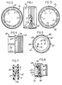
- FIGURE 1 illustrates a coupling ring 10 which has an internal annular shoulder 12 which includes a plurality of resiliently deflectable fingers 11.
- the coupling ring is preferably comprised of a one piece molded plastic material such as Torlon (Registered Trademark).
- FIGURE 2 illustrates a front view of the coupling ring shown in FIGURE 1 and illustrates how the fingers 11 project from the annular shoulder 12.
- FIGURE 3 illustrates a rear view of the coupling ring 10 shown in FIGURE 1 and illustrates how the fingers 11 are seen extending from the annular shoulder 12.
- FIGURE 4 illustrates housing 20 having a rear portion that includes threads 23; a forward portion that includes a key 24; an annular external shoulder 22 that includes a plurality of ramps 21; and a groove 29 for receiving a snap ring to retain a coupling ring.
- FIGURE 5 illustrates the front view of the housing shown in FIGURE 4.
- the housing 20 includes a plurality of electrical contacts 30 mounted therein and adapted to mate with electrical contacts of another connector housing (not shown).
- the plurality of ramps 21 are located at intervals along the annular external shoulder 22 of the housing 20.
- FIGURE 6 illustrates how the coupling ring 10 is rotatably mounted to the housing 20. This is generally accomplished by retaining annular shoulder 12 between a snap ring 40 and the shoulder 22 of the housing. As the coupling nut 10 is threaded onto a housing (not shown) the fingers 11 will travel across the projection 21 until the fingers are pressed against the coupling ring shoulder 12 and the housing shoulder 22. A nut 60 is shown mounted to the rear of the housing 20. The cutaway portion shows one of the contacts 30 mounted in the housing 20.
- FIGURE 7 illustrates an enlarged view of the deflectable fingers 11 of the coupling ring and the projections 21 on the shoulder 22 of the connector housing.
- the projections 21 on the housing are angled such that in one direction the fingers 11 slide freely across the projections but, in an opposite direction engage a face 21 A, which retards but does not prevent rotation in the opposite direction.
- This engagement of a free end 11 a of the deflectable finger 11 and the one face 21 a of the projection 21 provides an anti-decoupling feature when the coupling nut has been coupled to and completely threaded onto another housing of an electrical connector assembly.
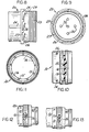
- FIGURE 8 illustrates another embodiment of the invention wherein the deflectable fingers that provides the biasing between a coupling nut (not shown) and a housing 20 are a plurality of fingers 26 integral with an external shoulder 27 on the housing 20.
- the front portion of the housing 20 includes a key 24 for aligning this housing with another housing (not shown); and the rear portion includes a plurality of threads 23 for connecting other parts to the housing 20 and a groove 29 for receiving a snap ring which retains a coupling ring.
- FIGURE 9 is a rear view of the housing shown in FIGURE 8 and illustrates a plurality of contacts 30 mounted within the housing 20; and the location of each of the deflectable fingers 26 around the outside and rear face of the shoulder 27.
- FIGURE 10 illustrates a coupling nut having an internal shoulder 16 that includes a plurality of projections 15 for providing an anti-de- coupling feature with the housing shown in FIGURE 8.
- the coupling ring 10 includes a plurality of apertures 14 for visually inspecting the engagement of the internal threads on the coupling ring 10 with the threads on another connector housing (not shown).
- FIGURE 11 illustrates a front view of the coupling ring shown in FIGURE 10 and illustrates how the plurality of projections 15 are located around the annular shoulder 16 on the inside of the coupling nut 10.
- FIGURE 12 illustrates the coupling ring shown in FIGURE 10 mounted to the housing shown in FIGURE 8.
- a cutaway view shows the inner action between the resilient fingers 26 on the housing 20 and the projections 15 of the coupling ring.
- FIGURE 13 illustrates the coupling ring- housing assembly shown in FIGURE 12 in its fully mated position with another housing 50. This illustrates how the fingers 26 have been completely deflected against the housing shoulder 27 to provide a rearward bias against the coupling ring 10 which in turn provides increased frictional force between the threads on the coupling ring 10 and the threads on the other housing 50. In addition to this additional frictional force to help prevent unwanted de- coupling, the ends of the fingers 26 engage the shoulders of projections 15 which are shaped to retard, but not prevent, rotation in a direction which will allow the coupling ring to be decoupled from the other housing.
- the fingers may be integral with either the connector housing or the coupling ring and the remaining piece may or may not have projections on it to inhibit rotation in a particular direction after the coupling nut has been fully seated on another connector housing.
Landscapes
- Details Of Connecting Devices For Male And Female Coupling (AREA)
- Connector Housings Or Holding Contact Members (AREA)
Claims (5)
Applications Claiming Priority (2)
| Application Number | Priority Date | Filing Date | Title |
|---|---|---|---|
| US206770 | 1980-11-14 | ||
| US06/206,770 US4359254A (en) | 1980-11-14 | 1980-11-14 | Electrical connector coupling ring having an integral spring |
Publications (2)
| Publication Number | Publication Date |
|---|---|
| EP0052530A1 EP0052530A1 (fr) | 1982-05-26 |
| EP0052530B1 true EP0052530B1 (fr) | 1984-09-19 |
Family
ID=22767880
Family Applications (1)
| Application Number | Title | Priority Date | Filing Date |
|---|---|---|---|
| EP81401527A Expired EP0052530B1 (fr) | 1980-11-14 | 1981-10-02 | Anneau de couplage de connecteur électrique ayant un ressort integré |
Country Status (5)
| Country | Link |
|---|---|
| US (1) | US4359254A (fr) |
| EP (1) | EP0052530B1 (fr) |
| JP (1) | JPS57109271A (fr) |
| CA (1) | CA1151258A (fr) |
| DE (1) | DE3166191D1 (fr) |
Families Citing this family (37)
| Publication number | Priority date | Publication date | Assignee | Title |
|---|---|---|---|---|
| US4462653A (en) * | 1981-11-27 | 1984-07-31 | Bendix Corporation | Electrical connector assembly |
| US4508406A (en) * | 1982-09-30 | 1985-04-02 | Allied Corporation | Electrical connector assembly having an anti-decoupling device |
| US4622198A (en) * | 1984-08-02 | 1986-11-11 | Allied Corporation | Method of making a coupling nut for an electrical connector having a molded anti-decoupling mechanism |
| US4548458A (en) * | 1984-08-02 | 1985-10-22 | Allied Corporation | Electrical connector having a molded anti-decoupling mechanism |
| US5145394A (en) * | 1991-10-03 | 1992-09-08 | G & H Technology, Inc. | Anti-rotation assembly for interconnect devices |
| US5246379A (en) * | 1992-03-02 | 1993-09-21 | Simmonds Precision Engine Systems, Inc. | Electrical connector and backshell assembly |
| FR2696049B1 (fr) * | 1992-09-21 | 1994-11-18 | Souriau & Cie | Connecteur électrique à bague filetée et verrouillage à prépondérance. |
| US5322451A (en) * | 1992-11-10 | 1994-06-21 | Woodhead Industries, Inc. | Vibration resistant electrical coupling with tactile indication |
| US5468161A (en) * | 1994-06-29 | 1995-11-21 | Simmonds Precision Engine Systems, Inc. | Semi-permanent electrical connector and backshell assembly |
| US5786976A (en) * | 1996-07-16 | 1998-07-28 | Hydraflow | Coupling with hard metallic ductile conductive coating |
| US5959828A (en) * | 1996-07-16 | 1999-09-28 | Hydraflow | Coupling with insulated flanges |
| US6135800A (en) * | 1998-12-22 | 2000-10-24 | Conxall Corporation | Anti-rotational electrical connector |
| US6036109A (en) * | 1999-02-01 | 2000-03-14 | Campbell Hausfeld/Scott Fetzer Company | Indexing aircap retaining ring |
| US6398586B1 (en) | 2001-05-01 | 2002-06-04 | Itt Manufacturing Enterprises, Inc. | Armored cable connector |
| FR2831720A1 (fr) * | 2001-10-25 | 2003-05-02 | Framatome Connectors Int | Systeme de connexion a verrouillage renforce |
| EP1617524A1 (fr) * | 2004-07-14 | 2006-01-18 | Coninvers Elektrotechnische Bauelemente GmbH | Connecteur électrique |
| FR2892568B1 (fr) * | 2005-10-20 | 2008-09-26 | Souriau Sa | Raccord pour element de contact |
| US9106012B2 (en) * | 2008-05-30 | 2015-08-11 | Itt Manufacturing Enterprises, Inc. | Antirotation coupling for connector |
| US9570845B2 (en) | 2009-05-22 | 2017-02-14 | Ppc Broadband, Inc. | Connector having a continuity member operable in a radial direction |
| US8287320B2 (en) | 2009-05-22 | 2012-10-16 | John Mezzalingua Associates, Inc. | Coaxial cable connector having electrical continuity member |
| US9017101B2 (en) | 2011-03-30 | 2015-04-28 | Ppc Broadband, Inc. | Continuity maintaining biasing member |
| US7905741B1 (en) | 2009-11-06 | 2011-03-15 | Amphenol Corporation | Anti-vibration connector coupling with an axially movable ratchet ring |
| US7914311B1 (en) | 2009-11-06 | 2011-03-29 | Amphenol Corporation | Anti-vibration connector coupling with an axially movable ratchet ring and a collar |
| US8337229B2 (en) | 2010-11-11 | 2012-12-25 | John Mezzalingua Associates, Inc. | Connector having a nut-body continuity element and method of use thereof |
| DE102011001079A1 (de) * | 2011-03-03 | 2012-09-06 | Phoenix Contact Gmbh & Co. Kg | Verbindungssystem eines Gehäuses eines Steckverbinders mit einer Mutter |
| US8366481B2 (en) | 2011-03-30 | 2013-02-05 | John Mezzalingua Associates, Inc. | Continuity maintaining biasing member |
| US9203167B2 (en) | 2011-05-26 | 2015-12-01 | Ppc Broadband, Inc. | Coaxial cable connector with conductive seal |
| US9711917B2 (en) | 2011-05-26 | 2017-07-18 | Ppc Broadband, Inc. | Band spring continuity member for coaxial cable connector |
| US9362634B2 (en) | 2011-12-27 | 2016-06-07 | Perfectvision Manufacturing, Inc. | Enhanced continuity connector |
| US8579644B2 (en) | 2012-03-13 | 2013-11-12 | Amphenol Corporation | Anti-vibration connector coupling with disengagement feature |
| US9397441B2 (en) * | 2013-03-15 | 2016-07-19 | Cinch Connections, Inc. | Connector with anti-decoupling mechanism |
| US9362666B2 (en) * | 2014-09-12 | 2016-06-07 | Cooper Technologies Company | Anti-decoupling spring |
| US9564695B2 (en) | 2015-02-24 | 2017-02-07 | Perfectvision Manufacturing, Inc. | Torque sleeve for use with coaxial cable connector |
| US10113669B2 (en) * | 2016-01-15 | 2018-10-30 | The Boeing Company | Pass-through bulkhead seal fitting |
| US10756482B2 (en) | 2016-09-20 | 2020-08-25 | Itt Manufacturing Enterprises Llc | Torque-limiting couplings |
| DE102019108700A1 (de) * | 2019-04-03 | 2020-10-08 | Turck Holding Gmbh | Zwei drehbare Teile aufweisende Vorrichtung, insbesondere elektrischer Steckverbinder |
| US20220239036A1 (en) * | 2019-05-24 | 2022-07-28 | Nokia Shanghai Bell Co., Ltd. | Communication System Connector |
Family Cites Families (6)
| Publication number | Priority date | Publication date | Assignee | Title |
|---|---|---|---|---|
| US2728895A (en) * | 1954-10-04 | 1955-12-27 | Whitney Blake Co | Self-locking coupling device |
| US3805379A (en) * | 1971-10-26 | 1974-04-23 | Trw Inc | Method of assembling an electrical connector to effect a preloading thereof |
| US3917373A (en) * | 1974-06-05 | 1975-11-04 | Bunker Ramo | Coupling ring assembly |
| US4030798A (en) * | 1975-04-11 | 1977-06-21 | Akzona Incorporated | Electrical connector with means for maintaining a connected condition |
| US4074927A (en) * | 1976-07-26 | 1978-02-21 | Automation Industries, Inc. | Electrical connector with insert member retaining means |
| US4168105A (en) * | 1978-06-27 | 1979-09-18 | Amp Incorporated | Resiliently loaded coupling ring |
-
1980
- 1980-11-14 US US06/206,770 patent/US4359254A/en not_active Expired - Lifetime
-
1981
- 1981-08-20 CA CA000384253A patent/CA1151258A/fr not_active Expired
- 1981-10-02 DE DE8181401527T patent/DE3166191D1/de not_active Expired
- 1981-10-02 EP EP81401527A patent/EP0052530B1/fr not_active Expired
- 1981-11-13 JP JP56181271A patent/JPS57109271A/ja active Pending
Also Published As
| Publication number | Publication date |
|---|---|
| EP0052530A1 (fr) | 1982-05-26 |
| CA1151258A (fr) | 1983-08-02 |
| US4359254A (en) | 1982-11-16 |
| JPS57109271A (en) | 1982-07-07 |
| DE3166191D1 (en) | 1984-10-25 |
Similar Documents
| Publication | Publication Date | Title |
|---|---|---|
| EP0052530B1 (fr) | Anneau de couplage de connecteur électrique ayant un ressort integré | |
| US4349241A (en) | Electrical connector assembly having enhanced EMI shielding | |
| US4464001A (en) | Coupling nut having an anti-decoupling device | |
| US4389081A (en) | Electrical connector coupling ring | |
| US6450829B1 (en) | Snap-on plug coaxial connector | |
| US4938718A (en) | Cylindrical connector keying means | |
| US4165910A (en) | Electrical connector | |
| US4239314A (en) | Electrical connector | |
| US6361348B1 (en) | Right angle, snap on coaxial electrical connector | |
| US4359255A (en) | Coupling ring having detent means | |
| US4334730A (en) | Insulated from ground bulkhead adapter | |
| US5336101A (en) | Connector assembly | |
| US4443052A (en) | Means to indicate fully-mated condition of electrical connector | |
| US5857869A (en) | Spring latch for use with cable connectors | |
| US4497530A (en) | Electrical connector having a coupling indicator | |
| EP0080930A2 (fr) | Ensemble de connecteurs électriques | |
| CA1227842A (fr) | Connecteur electrique a dispositif de verrouillage | |
| US4359256A (en) | Electrical connector coupling member | |
| US4519661A (en) | Connector assembly having an anti-decoupling mechanism | |
| US4362349A (en) | Electrical connector housing with integral retention mechanism | |
| US4762504A (en) | Connector coupling lock | |
| US4361373A (en) | Electrical connector comprised of plastic | |
| US4468078A (en) | Forwardly removable coupling ring for an electrical connector | |
| US10938152B2 (en) | Electrical connector assembly | |
| EP0123096A1 (fr) | Assemblage de contacts électriques à socle se composant de deux pièces |
Legal Events
| Date | Code | Title | Description |
|---|---|---|---|
| PUAI | Public reference made under article 153(3) epc to a published international application that has entered the european phase |
Free format text: ORIGINAL CODE: 0009012 |
|
| 17P | Request for examination filed |
Effective date: 19811016 |
|
| AK | Designated contracting states |
Designated state(s): DE FR GB IT |
|
| ITF | It: translation for a ep patent filed | ||
| GRAA | (expected) grant |
Free format text: ORIGINAL CODE: 0009210 |
|
| AK | Designated contracting states |
Designated state(s): DE FR GB IT |
|
| REF | Corresponds to: |
Ref document number: 3166191 Country of ref document: DE Date of ref document: 19841025 |
|
| ET | Fr: translation filed | ||
| PLBE | No opposition filed within time limit |
Free format text: ORIGINAL CODE: 0009261 |
|
| STAA | Information on the status of an ep patent application or granted ep patent |
Free format text: STATUS: NO OPPOSITION FILED WITHIN TIME LIMIT |
|
| 26N | No opposition filed | ||
| PGFP | Annual fee paid to national office [announced via postgrant information from national office to epo] |
Ref country code: FR Payment date: 19891016 Year of fee payment: 9 |
|
| PGFP | Annual fee paid to national office [announced via postgrant information from national office to epo] |
Ref country code: DE Payment date: 19891025 Year of fee payment: 9 |
|
| ITTA | It: last paid annual fee | ||
| PGFP | Annual fee paid to national office [announced via postgrant information from national office to epo] |
Ref country code: GB Payment date: 19891031 Year of fee payment: 9 |
|
| PG25 | Lapsed in a contracting state [announced via postgrant information from national office to epo] |
Ref country code: GB Effective date: 19901002 |
|
| GBPC | Gb: european patent ceased through non-payment of renewal fee | ||
| PG25 | Lapsed in a contracting state [announced via postgrant information from national office to epo] |
Ref country code: FR Effective date: 19910628 |
|
| PG25 | Lapsed in a contracting state [announced via postgrant information from national office to epo] |
Ref country code: DE Effective date: 19910702 |
|
| REG | Reference to a national code |
Ref country code: FR Ref legal event code: ST |