EP0052583A1 - A fastener for a necklace, chain or other jewellery item - Google Patents
A fastener for a necklace, chain or other jewellery item Download PDFInfo
- Publication number
- EP0052583A1 EP0052583A1 EP81830219A EP81830219A EP0052583A1 EP 0052583 A1 EP0052583 A1 EP 0052583A1 EP 81830219 A EP81830219 A EP 81830219A EP 81830219 A EP81830219 A EP 81830219A EP 0052583 A1 EP0052583 A1 EP 0052583A1
- Authority
- EP
- European Patent Office
- Prior art keywords
- fastener
- component
- external component
- internal component
- internal
- Prior art date
- Legal status (The legal status is an assumption and is not a legal conclusion. Google has not performed a legal analysis and makes no representation as to the accuracy of the status listed.)
- Withdrawn
Links
- 238000003780 insertion Methods 0.000 claims abstract description 6
- 230000037431 insertion Effects 0.000 claims abstract description 6
- 239000002184 metal Substances 0.000 claims description 4
- 229910052751 metal Inorganic materials 0.000 claims description 4
- 238000003801 milling Methods 0.000 claims description 4
- 238000010008 shearing Methods 0.000 claims description 4
- 238000005266 casting Methods 0.000 claims description 3
- 238000005553 drilling Methods 0.000 claims description 2
- 230000014759 maintenance of location Effects 0.000 claims description 2
- 238000000034 method Methods 0.000 claims description 2
- 230000000994 depressogenic effect Effects 0.000 claims 1
- 241001646071 Prioneris Species 0.000 description 6
- 238000010276 construction Methods 0.000 description 5
- 210000004905 finger nail Anatomy 0.000 description 3
- 230000000881 depressing effect Effects 0.000 description 2
- 239000000463 material Substances 0.000 description 2
- 238000004080 punching Methods 0.000 description 2
- 238000009713 electroplating Methods 0.000 description 1
- 239000010970 precious metal Substances 0.000 description 1
- 238000003466 welding Methods 0.000 description 1
Images


Classifications
-
- A—HUMAN NECESSITIES
- A44—HABERDASHERY; JEWELLERY
- A44C—PERSONAL ADORNMENTS, e.g. JEWELLERY; COINS
- A44C5/00—Bracelets; Wrist-watch straps; Fastenings for bracelets or wrist-watch straps
- A44C5/18—Fasteners for straps, chains or the like
- A44C5/20—Fasteners for straps, chains or the like for open straps, chains or the like
- A44C5/2019—Hooks
- A44C5/2023—Sliding hooks
Definitions
- This invention relates to a fastener for securing together the two ends of a necklace or for use in similar circumstances on other jewellery items or devices of precious metals.
- One object of the invention is to provide a simple and economical though also reliably-operating and safe fastener device.
- a fastener for securing the two ends of an item of jewellery characterised by two components; one of which is an internal component (1) having means (14). for securement to one end (c) of the jewellery item and forming a hook (16) to be attached to the other end of the item, the other component being an external component (10) slidably engaged with the internal component (1), between a closed position of the hook (16) and an open position allowing the insertion and removal of the other end of the jewellery item, the said internal component having a resilient arm (5a) resiliently engageable with the external component (10) to hold the fastener in the said closed position.
- the internal component can be advantageously produced by means of sheared thin metal sheeting.
- the internal component may be made of suitably shaped wire.
- the external component may consist of a tubular sheath, though it may also be moulded for aesthetic reasons, being achieved by casting or otherprocess.
- the internal component is developed to form a resilient arm which will resiliently yield and having a shaped projection which will engage in a recess formed internally within the sheath-like external component.
- the said resilient arm may have an actuating lug for application of pressure so as to fascilitate the opening operation.
- an opening which defines the resilient arm forms within the internal component an opening for fixed retention of one end of a necklace, chain or other jewellery item onto the fastener.
- the jewellery item may thus be secured to the internal component before fitting the external component thereto.
- the external component may be tubular and flattened and have a recess produced by drilling, shearing, milling or punching, arranged to be engaged by a lug on the resilient arm to retain the fastener in the closed position.
- the internal component may be shaped to allow sliding within the sheath-like external component, the sliding movement being prevented in one direction by a link of the jewellery item such as a necklace, chain or the like secured to the fastener.
- the internal component may have an enlarged part forming a stop against one extreme end of the sheath-like external component.
- the external component and the internal component may be separately finished (by electroplating or other), being fitted together subsequently without prejudice to the operation or to the finish.
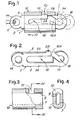
- a necklace chain or like fastener having an internal component 1 made from sheared thin sheet metal and a sheath-like external component 10.
- the internal component 1 is provided with two parallel.edges 3, 5 serving as guide edges to slidably engage between corresponding internal guide edges 7 and 9 of the sheath-like external component 10.
- the said external component 10 in this example is of shaped tubular section, simply cut to length, or as rolled.
- the external component 10 is subsequently machined with a simple milling cutter to form a recess 12 breaking through the edge 9, thereby forming an actuating opening.
- External component 10 may alternatively be made by casting or other processes, with a cavity forming a prismatic guide having moulded as well as formed surface.
- Component 1 has an eyelet or ring 14 at one end, serving as a fixed retainer to one of the ends of the necklace, chain or the like, as indicated at C in fig. 1.
- the component 1 has an open ring or hook of enlarged size at 1A, in which a hook seating 16 is formed with an access chaimel-16A towards the edge 5 of the component.
- Component 1 has an extensive longitudinal slot 18 extending between and parallel with the edges 3 and 5 and defining two arms 3A and 5A, bounded respectively by the edges 3 and 5, arm 3A connects the eyelet or ring 14 with the hook part 1A forming the hook seating 16, while arm 5A is isolated and free at the end adjacent to the eyelet or ring 14; at the end of the arm 5A an outward projection 5B at the edge 5 is provided for engagement in the recess 12 of the external component 10 the arm 5A with the projection 5B is resilient.
- the fastener consisting of the two components 1 and 10 is coupled by inserting into the sheath-like component 10, the end of the component 1 having the eyelet or ring 14.
- the arm 5b yields resiliently inwards, i.e. towards the arm 3A when the projection 5B has to penetrate into the sheath-like component 10; when the projection 5B reaches the recess 12, the arm 5A moves resiliently outwardly once more so that the assembly takes up the position shown in Fig. 1. In that form the access channel 16A to the hook seating 16 is inside the sheath-like component 10. After fitting the assembly as shown in Fig. 1, the link C of the necklace or the like is attached to the eyelet or ring 14.
- the two ends of the necklace, chain or the like, connected by the fastener are both secured to the internal component 1, which allows sufficient traction resistance.
- the fastener can only be opened by forcing the external component, 10 to slide against the resilience of the arm 5A with the projection 5B, which can be overcome (providing the projection profile 5B allows it) by means of sliding, or after depressing the projection 5B in the direction of arrow F2 for instance with the finger nail.
- the external component 10 remains secured between the hook 1A and the link C after fitting of the fastener. Before fitting of the fastener, component 10 is held on component 1 by the resilient retaining action of the projection 5B.
- Figs; 5 to 8 show a similar arrangement to the previous example.
- the internal component 21 and external component 23 are of similar structure to that of components 1 and 10 component 23 having a recess 32 similar to that at 12 in Figures 1 and 3.
- the internal component 21 has a hook seating 36 similar to that at 16, with an access channel 36A similar to that at 16A, the seating 36 being formed at one end 21A of the component 21 and having a width of no greater than the distance between the two guide edges 23 and 25 corresponding to the edges 3 and 5 in the previous example for guiding within edges 27 and 29 of the external component 23 similarly to edges 7 and 9.
- a longitudinal slot 38 similar to that at 18 is defined between two arms 23A and 25A formed by the component 21 and having the respective edges 23 and 25.
- the slot 38 has an opening which is at the end of the resilient arm 25A and is the access channel 36A, so as to allow insertion in the direction of the arrow F3 in Fig. 6, of a link to be secured to the fastener as indicated in C1 in Fig. 5.
- a sawtooth projection 25B is substituted, allowing insertion of the external component 23 over the internal component 21, with a relative sliding movement of component 23 in the direction of the arrow F4 relatively to component 21.
- the link C1 Before placing component 23 on component 21, the link C1 is inserted in the slot 38 as indicated by arrow F3 in Fig. 6, until it engages at the end of the slot 38.
- the tooth 25B After sliding the component 23 over component 21 by flexing of the arm 25A in relation to arm 23A, the tooth 25B is able b reach the recess 32 and drop into it as shown in Fig. 5.
- component 23 In that locked position component 23 is unable to slide in a direction opposite to arrow F4 in relation to the internal component 21.
- the external component 23 may be moved from the position shown in Fig. 5 in the direction of arrow F4 in relation to component 21, until the access channel 36A is outside of component 23.
- the sliding of component 23 is allowed by the slope of the side of the saw-tooth projection 25B, the permitted travel being limited by engagement between component 23 and link C1.
- the external component 23 is moved in the reverse direction to arrow F4 in relation to component 21, until the saw- tooth projection 25B returns resiliently into the seating formed by the recess 32, preventing any further movement of component 23.
- the resilient distortion of arm 25A towards arm 23A to allow opening of the fastener is achieved by forcing the two components to slide lengthwise the slope of the saw-tooth projection 25B pushing arm 25A towards arm 23A. Additional pressure with the finger-nail will facilitate this operation.
- Figs. 9 to 12 show a fastener in which an internal component 41 is shown, also produced by shearing, and a sheath-like external component 43 produced in a similar manner to the corresponding components in previous examples.
- the external component 43 has an opening or recess 45 similar to those at 12 and 32, as well as a longitudinal slit 47 starting from one of the end of the sheath-like component.
- the internal component 41 has edges 49, 50 parallel with each other to guide the internal component into the external component 43.
- the edge 49 is formed by an arm 49A extending to form a hook 41A defining a seating 52 similar to those at 16 and 36, with an access channel 52A between the ends of hook 41A and the end of an arm 50A which defines the edge 50.
- a slot 54 defined between the two arms 49A and 50A is formed within internal component 41.
- the arrangement is such that the arm 50A will yield resiliently whereas the slot 54 and seating 52 are accessible from the access channel 52A between the end of hook 41A and the end of the arm 50A.
- Near the end of arm - 50A there is provided with a saw-tooth projection 55 similar to that at 25B but pointing in the opposite direction.
- a lug 57 is formed at the end of the arm 50A for actuation purposes, this being at a small distance from the projection 55.
- An eyelet or ring 59 is formed at the opposite end of the component 41 from the hook 41A which provides the seating 52.
- the sheath-like external component 43 may be inserted over the component 41 in the direction of the arrow F9 in Fig.'9.
- the fastener In this position the fastener can be engaged by the end link C2 of the necklace, chain or the like, through the eyelet or ring 59 so as to keep the fastener fixed at that end of the necklace, chain or the like.
- the closed position of the fastener is secured by the double lock of the projection 55 and the lug 57. It is only by depressing in the direction of the arrow FA on the lug 57, thereby deflecting the arm 50A towards arm 49A, that the sheath-like component 43 can be made to release to slide in the reverse direction to arrow F9 in relation to the internal component 41, when the projection 55 moves inward from the recess 45.
- Reverse sliding in the opposite direction to arrow F9 is limited by the presence of the link C2 of the necklace, chain or the like, but travel is sufficient since the access channel 52A can be exposed sufficiently to allow the link at the other end of the necklace, chain or the like to be inserted into it.
- Moving the sheath-like external component 43 in the other direction, that is in the direction of the arrow F9 again locks the two components relatively to one another as the projection 55 engages into the recess 45.
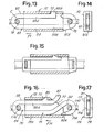
- Figs 13 and 14 show a variation on the example in Figs. 1 to 4, wherein the corresponding components and features bear the same reference number with the addition of 60 to each.
- the slot 78 in this particular case directly forms the seating for link C, without recourse to an eyelet or ring as at 14.
- a projecting tooth 61A is provided, preventing the sheath-like external component 70 from sliding in the direction opposite to arrow F1 in relation to the internal component 60.
- Fig. 15 shows a similar construction to that in Fig. 13 but with square in place of rounded ends to the internal component, at 78 and 76, for use in securing very flat necklace, chain or bracelet ends. It also has a saw tooth projection.
- Figs. 16 and 17 show a variation on the examples in Figs. 9 to 12, in which corresponding components and parts bear the same reference number plus with the addition of 80 to each.
- the slot 84 is extended to form a seating for the link C32, whereby it can be securely fixed to the fastener and the slot 84 is defined between the two arms 79A and 80A.
- the arm 79A has an S shaped profile defining the hook 71A of the internal component 71, with a seating 82 for receiving the releasable link C42 at the other end of the necklace, chain or the like; the said seating 82 opens at 82A at the opposite side to the flexible arm 80A which bears the tooth projection 85, engageable in the recess 75.
- a lug 87 is lodged in and projects through a longitudinal slit, formed by a sloping surface 77.
- the operation is the same as for the example in Figs. 9 to 12, except for the possibility of inserting the link C32 into the slit 84, before fitting the internal component 81 inside the external component 73 in the direction of the arrow F71.
- the external component may be made with tubular profile with transverse cuts defining the ends and by milling, or some other operation the recess 12, 32, 45, 72 or 75 and slit 47 can be formed.
- the external component may be made from sheared and pressed sheet metal. The latter case does not exclude actuation of the external components with an open transverse profile or an annular closed profile.
- the internal component is also easily produced from easily machined drawn material or even more simply by shearing or other easy operations.
- the internal component may be made of wire or similar material, particularly in the case of Figs. 5 to 8.
- the internal component acts in the manner of a spring with the resilient arm 5A or 25A or 50A and also defines the eyelets or seatings for the end links, both fixed and removable, on the ends of the necklace, chain or the like; on the other hand the external component does not require an eyelet.
- the necklace, chain or the like may be fitted in a preliminary manner before securing the two components of the fastener. In each case it is possible to proceed with separate easy finishing processing of the two components, without the risk of subsequent operations damaging the surface finish of the components.
- the recess 12, 32, 45, 72 or 75 may be made by internal punching, so that the recess is not accessible from the outside, in which case after the fitting of the two components and the welding of the link C1 the two components may no longer be separated.
Landscapes
- Adornments (AREA)
- Hooks, Suction Cups, And Attachment By Adhesive Means (AREA)
- Mutual Connection Of Rods And Tubes (AREA)
Applications Claiming Priority (2)
| Application Number | Priority Date | Filing Date | Title |
|---|---|---|---|
| IT09595/80A IT1136076B (it) | 1980-11-19 | 1980-11-19 | Fermaglio per catenelle ed altri monili |
| IT959580 | 1980-11-19 |
Publications (1)
| Publication Number | Publication Date |
|---|---|
| EP0052583A1 true EP0052583A1 (en) | 1982-05-26 |
Family
ID=11132590
Family Applications (1)
| Application Number | Title | Priority Date | Filing Date |
|---|---|---|---|
| EP81830219A Withdrawn EP0052583A1 (en) | 1980-11-19 | 1981-11-10 | A fastener for a necklace, chain or other jewellery item |
Country Status (3)
| Country | Link |
|---|---|
| EP (1) | EP0052583A1 (it) |
| JP (1) | JPS57127121A (it) |
| IT (1) | IT1136076B (it) |
Cited By (6)
| Publication number | Priority date | Publication date | Assignee | Title |
|---|---|---|---|---|
| FR2531322A1 (fr) * | 1982-08-03 | 1984-02-10 | Leroux Jacques | Fermoir pour chaine de collier |
| GB2175192A (en) * | 1985-03-26 | 1986-11-26 | Kirsch Maurice | Fastening means |
| GB2204631A (en) * | 1987-05-08 | 1988-11-16 | Toho Shoji Kk | Releasable connectors |
| US11071358B2 (en) | 2016-08-28 | 2021-07-27 | Mango Tree Jewelry Ltd. | Interchangeable jewelry linking system and clasps thereof |
| KR20220125202A (ko) * | 2019-12-20 | 2022-09-14 | 김천회 | 신변 장신구용 빗장 연결고리 |
| CN115137135A (zh) * | 2022-08-02 | 2022-10-04 | 深圳市周大福珠宝制造有限公司 | 一种首饰扣及具有该首饰扣的首饰 |
Citations (9)
| Publication number | Priority date | Publication date | Assignee | Title |
|---|---|---|---|---|
| FR392235A (fr) * | 1908-07-10 | 1908-11-20 | Ernest Cheneble | Système de cadenas de bijouterie |
| FR499037A (fr) * | 1919-05-06 | 1920-01-29 | Emery Jardin | Dispositif de fermoir pour chaines ou chainettes |
| US1405227A (en) * | 1920-03-26 | 1922-01-31 | Frank Wiegand | Jewelry snap fastener |
| GB247444A (en) * | 1925-06-10 | 1926-02-18 | Joseph James Morse | Improvements in snap fastenings for necklets and similar articles of jewellery |
| US1771427A (en) * | 1929-04-19 | 1930-07-29 | George H Waterhouse | Clasp for articles of jewelry |
| DE961227C (de) * | 1954-02-26 | 1957-04-04 | Augusto Enrique Hestermann | Schliesse fuer Schmuckstuecke |
| FR86919E (fr) * | 1964-10-15 | 1966-05-06 | Gay Freres Ets | Fermoir perfectionné pour chaîne, bracelet ou analogue |
| FR1503850A (fr) * | 1966-10-14 | 1967-12-01 | Gay Freres | Fermoir perfectionné |
| EP0029410A1 (fr) * | 1979-11-16 | 1981-05-27 | Attilio Brentini | Fermoir |
-
1980
- 1980-11-19 IT IT09595/80A patent/IT1136076B/it active
-
1981
- 1981-11-10 EP EP81830219A patent/EP0052583A1/en not_active Withdrawn
- 1981-11-19 JP JP56184551A patent/JPS57127121A/ja active Pending
Patent Citations (9)
| Publication number | Priority date | Publication date | Assignee | Title |
|---|---|---|---|---|
| FR392235A (fr) * | 1908-07-10 | 1908-11-20 | Ernest Cheneble | Système de cadenas de bijouterie |
| FR499037A (fr) * | 1919-05-06 | 1920-01-29 | Emery Jardin | Dispositif de fermoir pour chaines ou chainettes |
| US1405227A (en) * | 1920-03-26 | 1922-01-31 | Frank Wiegand | Jewelry snap fastener |
| GB247444A (en) * | 1925-06-10 | 1926-02-18 | Joseph James Morse | Improvements in snap fastenings for necklets and similar articles of jewellery |
| US1771427A (en) * | 1929-04-19 | 1930-07-29 | George H Waterhouse | Clasp for articles of jewelry |
| DE961227C (de) * | 1954-02-26 | 1957-04-04 | Augusto Enrique Hestermann | Schliesse fuer Schmuckstuecke |
| FR86919E (fr) * | 1964-10-15 | 1966-05-06 | Gay Freres Ets | Fermoir perfectionné pour chaîne, bracelet ou analogue |
| FR1503850A (fr) * | 1966-10-14 | 1967-12-01 | Gay Freres | Fermoir perfectionné |
| EP0029410A1 (fr) * | 1979-11-16 | 1981-05-27 | Attilio Brentini | Fermoir |
Cited By (6)
| Publication number | Priority date | Publication date | Assignee | Title |
|---|---|---|---|---|
| FR2531322A1 (fr) * | 1982-08-03 | 1984-02-10 | Leroux Jacques | Fermoir pour chaine de collier |
| GB2175192A (en) * | 1985-03-26 | 1986-11-26 | Kirsch Maurice | Fastening means |
| GB2204631A (en) * | 1987-05-08 | 1988-11-16 | Toho Shoji Kk | Releasable connectors |
| US11071358B2 (en) | 2016-08-28 | 2021-07-27 | Mango Tree Jewelry Ltd. | Interchangeable jewelry linking system and clasps thereof |
| KR20220125202A (ko) * | 2019-12-20 | 2022-09-14 | 김천회 | 신변 장신구용 빗장 연결고리 |
| CN115137135A (zh) * | 2022-08-02 | 2022-10-04 | 深圳市周大福珠宝制造有限公司 | 一种首饰扣及具有该首饰扣的首饰 |
Also Published As
| Publication number | Publication date |
|---|---|
| JPS57127121A (en) | 1982-08-07 |
| IT1136076B (it) | 1986-08-27 |
| IT8009595A0 (it) | 1980-11-19 |
Similar Documents
| Publication | Publication Date | Title |
|---|---|---|
| US6481069B1 (en) | Bracelet connector | |
| US4286360A (en) | Jewelry clasp | |
| US4408375A (en) | Releasable connector | |
| US4916779A (en) | Adjustable fastener | |
| US5586368A (en) | Locking attachment | |
| TW312103U (en) | Lock slider for slide fastener | |
| US4494310A (en) | Belt buckle knife | |
| DE3432168A1 (de) | Schnappverschluss fuer das loesbare verbinden zweier gegenstaende | |
| EP0052583A1 (en) | A fastener for a necklace, chain or other jewellery item | |
| US4534090A (en) | Releasable clasp | |
| US4152814A (en) | Swivel hook | |
| US4022506A (en) | Zipper operator | |
| US4246680A (en) | Jewelry clasp | |
| US4747165A (en) | Belt and buckle | |
| EP1295542A3 (en) | Slider for slide fastener | |
| US7676894B2 (en) | Clasp for jewelry, especially for necklaces and bracelets | |
| KR840000533Y1 (ko) | 버클(혁대를 죄는 쇠 buckle) | |
| US2882577A (en) | Operator for slide fasteners | |
| US3574903A (en) | Fastening device for a wristwatch band and the like | |
| EP3516981B1 (en) | Closure device for gold, silver and costume jewellery items | |
| US4566159A (en) | Safety clasp for a necklace or bracelet chain | |
| US4281441A (en) | Jewelry clasp | |
| US5737809A (en) | Lead attachment device | |
| US4358875A (en) | Security buckle for wrist watch metal bracelets | |
| US4074400A (en) | Fastenings suitable for personal ornaments |
Legal Events
| Date | Code | Title | Description |
|---|---|---|---|
| PUAI | Public reference made under article 153(3) epc to a published international application that has entered the european phase |
Free format text: ORIGINAL CODE: 0009012 |
|
| AK | Designated contracting states |
Designated state(s): BE CH DE FR GB NL |
|
| 17P | Request for examination filed |
Effective date: 19821230 |
|
| STAA | Information on the status of an ep patent application or granted ep patent |
Free format text: STATUS: THE APPLICATION IS DEEMED TO BE WITHDRAWN |
|
| 18D | Application deemed to be withdrawn |
Effective date: 19840601 |
|
| RIN1 | Information on inventor provided before grant (corrected) |
Inventor name: LUCANI, RAFFAELLO |