EP0052675B1 - Système et méthode de mise à feu d'une roquette - Google Patents
Système et méthode de mise à feu d'une roquette Download PDFInfo
- Publication number
- EP0052675B1 EP0052675B1 EP80304163A EP80304163A EP0052675B1 EP 0052675 B1 EP0052675 B1 EP 0052675B1 EP 80304163 A EP80304163 A EP 80304163A EP 80304163 A EP80304163 A EP 80304163A EP 0052675 B1 EP0052675 B1 EP 0052675B1
- Authority
- EP
- European Patent Office
- Prior art keywords
- coil
- firing
- rocket
- magnetic core
- driver
- Prior art date
- Legal status (The legal status is an assumption and is not a legal conclusion. Google has not performed a legal analysis and makes no representation as to the accuracy of the status listed.)
- Expired
Links
- 238000010304 firing Methods 0.000 title claims description 50
- 238000000034 method Methods 0.000 title claims description 7
- 230000001939 inductive effect Effects 0.000 claims description 9
- 230000004907 flux Effects 0.000 claims description 4
- 235000015842 Hesperis Nutrition 0.000 description 2
- 235000012633 Iberis amara Nutrition 0.000 description 2
- 238000001514 detection method Methods 0.000 description 2
- 230000000694 effects Effects 0.000 description 1
- 230000035945 sensitivity Effects 0.000 description 1
Images
Classifications
-
- F—MECHANICAL ENGINEERING; LIGHTING; HEATING; WEAPONS; BLASTING
- F41—WEAPONS
- F41A—FUNCTIONAL FEATURES OR DETAILS COMMON TO BOTH SMALLARMS AND ORDNANCE, e.g. CANNONS; MOUNTINGS FOR SMALLARMS OR ORDNANCE
- F41A19/00—Firing or trigger mechanisms; Cocking mechanisms
-
- F—MECHANICAL ENGINEERING; LIGHTING; HEATING; WEAPONS; BLASTING
- F41—WEAPONS
- F41A—FUNCTIONAL FEATURES OR DETAILS COMMON TO BOTH SMALLARMS AND ORDNANCE, e.g. CANNONS; MOUNTINGS FOR SMALLARMS OR ORDNANCE
- F41A19/00—Firing or trigger mechanisms; Cocking mechanisms
- F41A19/58—Electric firing mechanisms
- F41A19/63—Electric firing mechanisms having means for contactless transmission of electric energy, e.g. by induction, by sparking gap
-
- F—MECHANICAL ENGINEERING; LIGHTING; HEATING; WEAPONS; BLASTING
- F42—AMMUNITION; BLASTING
- F42C—AMMUNITION FUZES; ARMING OR SAFETY MEANS THEREFOR
- F42C17/00—Fuze-setting apparatus
- F42C17/04—Fuze-setting apparatus for electric fuzes
-
- F—MECHANICAL ENGINEERING; LIGHTING; HEATING; WEAPONS; BLASTING
- F42—AMMUNITION; BLASTING
- F42C—AMMUNITION FUZES; ARMING OR SAFETY MEANS THEREFOR
- F42C21/00—Checking fuzes; Testing fuzes
Definitions
- This invention relates to a rocket firing system and to a method of firing a rocket; the rocket firing system is positioned on a launcher device.
- the invention provides a rocket firing system comprising a magnetic cord and a driver coil mounted co-axial therewith for inducing a firing voltage in a rocket firing circuit coil brought into inductive linkage with the core, characterised in that means are provided for effecting a pre-firing check, said means comprising a sensor coil inductively linked with the core and driver coil and a detector device connected to the sensor coil to determine the presence and state of a said rocket firing circuit coil.
- the sensor coil is in two parts lying transversely of and closely adjacent the driver coil.
- the firing system may be embodied in a rocket launcher device.
- the invention provides a method of firing a rocket having an inductive firing circuit adapted to be magnetically linked by a firing system having a magnetic core and a driver coil, wherein first the core is brought to link magnetically with the firing circuit, then a low-power signal voltage is applied to the driver coil, the presence and state of the firing circuit being monitored by a signal regenerated in a sensor coil, and thereafter an operating power voltage is applied to the driver coil so as to induce a firing voltage in the firing circuit.
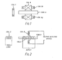
- the firing system which is mounted on the rocket launcher comprises in essence a magnetic core D, which is surrounded by a driver coil A.
- a sensor coil B mounted in close physical proximity to the coil A is a sensor coil B which is divided into two part 8, and B 2 .
- the coil B has its magnetic axis perpendicular to that of coil A and to the core D.
- the system is positioned on the launcher such that the core D aligns with a coil C mounted on a rocket positioned in the launcher.
- the coil C is connected in circuit with a detonator match in the form of a low-voltage, high-current hot wire coil onto which has been deposited a heat sensitive pyrotechnic material.
- the firing circuit driving coil C has an internal diameter larger than the core D, and when the rocket is in position, the core D enters the coil C and makes an inductive link therewith.
- Coil A is connectible to a suitable alternating current supply and which is controlled at two power levels, a low power signal level for testing purposes and a full operating power level for firing.
- the coil B is connected to a suitable voltage detection circuit.
- the firing system is set up by moving core D with no rocket present and with the coil A energised at the signal level until the induced voltage in coil B is at a minimum. The core D is then locked in position.
- the coil parts 8, and 8 2 are wound in position, and positioned so that one part will cut more flux than the other when the flux pattern becomes asymmetrically distorted by the presence of coil C. This gives a greater sensitivity, and since signal in coil B is a minimum in the balance of a rocket, allows the use of a threshold detector in the circuit to eliminate external effects.
- the coil parts are preferably connected in a bridge circuit. A single sensor coil, or one co-axial with the core D, could in theory be used but is very much less sensitive.
- two sensor coils coaxial with the core D are used, preferably in a bridge circuit.
- Such a firing system is adapted well to being applied to a series of launchers, and testing and firing can be carried out remotely, either sequentially or in unison.
Landscapes
- Engineering & Computer Science (AREA)
- General Engineering & Computer Science (AREA)
- Measurement Of Length, Angles, Or The Like Using Electric Or Magnetic Means (AREA)
Claims (10)
Priority Applications (4)
| Application Number | Priority Date | Filing Date | Title |
|---|---|---|---|
| GB7923707A GB2055181B (en) | 1979-07-06 | 1979-07-06 | Rocket firing system |
| AT80304163T ATE13224T1 (de) | 1980-11-20 | 1980-11-20 | Einrichtung und verfahren zur abfeuerung von raketen. |
| DE8080304163T DE3070627D1 (en) | 1980-11-20 | 1980-11-20 | A rocket firing system and a method of firing a rocket |
| EP80304163A EP0052675B1 (fr) | 1979-07-06 | 1980-11-20 | Système et méthode de mise à feu d'une roquette |
Applications Claiming Priority (2)
| Application Number | Priority Date | Filing Date | Title |
|---|---|---|---|
| GB7923707A GB2055181B (en) | 1979-07-06 | 1979-07-06 | Rocket firing system |
| EP80304163A EP0052675B1 (fr) | 1979-07-06 | 1980-11-20 | Système et méthode de mise à feu d'une roquette |
Publications (2)
| Publication Number | Publication Date |
|---|---|
| EP0052675A1 EP0052675A1 (fr) | 1982-06-02 |
| EP0052675B1 true EP0052675B1 (fr) | 1985-05-08 |
Family
ID=26079968
Family Applications (1)
| Application Number | Title | Priority Date | Filing Date |
|---|---|---|---|
| EP80304163A Expired EP0052675B1 (fr) | 1979-07-06 | 1980-11-20 | Système et méthode de mise à feu d'une roquette |
Country Status (2)
| Country | Link |
|---|---|
| EP (1) | EP0052675B1 (fr) |
| GB (1) | GB2055181B (fr) |
Citations (1)
| Publication number | Priority date | Publication date | Assignee | Title |
|---|---|---|---|---|
| GB1235844A (en) * | 1967-10-17 | 1971-06-16 | Ml Aviation Co Ltd | Electrical ignition of explosive devices |
Family Cites Families (5)
| Publication number | Priority date | Publication date | Assignee | Title |
|---|---|---|---|---|
| US3123002A (en) * | 1964-03-03 | Spool | ||
| GB640893A (en) * | 1940-07-22 | 1950-08-02 | Standard Telephones Cables Ltd | Magnetic detectors, especially applicable to locomotive torpedoes |
| US2555384A (en) * | 1948-01-14 | 1951-06-05 | Gordon J Watt | Electrically set mechanical time fuse |
| US4142442A (en) * | 1971-12-08 | 1979-03-06 | Avco Corporation | Digital fuze |
| CH589838A5 (fr) * | 1975-03-10 | 1977-07-15 | Oerlikon Buehrle Ag |
-
1979
- 1979-07-06 GB GB7923707A patent/GB2055181B/en not_active Expired
-
1980
- 1980-11-20 EP EP80304163A patent/EP0052675B1/fr not_active Expired
Patent Citations (1)
| Publication number | Priority date | Publication date | Assignee | Title |
|---|---|---|---|---|
| GB1235844A (en) * | 1967-10-17 | 1971-06-16 | Ml Aviation Co Ltd | Electrical ignition of explosive devices |
Also Published As
| Publication number | Publication date |
|---|---|
| GB2055181B (en) | 1982-11-24 |
| EP0052675A1 (fr) | 1982-06-02 |
| GB2055181A (en) | 1981-02-25 |
Similar Documents
| Publication | Publication Date | Title |
|---|---|---|
| US4273051A (en) | Electric device | |
| US2331058A (en) | Firing apparatus for gun perforators | |
| EP0013835B1 (fr) | Circuit de commande pour détonateur électrique à déclenchement sélectif et détonateurs comportant un tel circuit | |
| US4377113A (en) | Rocket firing system | |
| US5572135A (en) | Diagnostic apparatus and methods for ignition circuits | |
| EP0052675B1 (fr) | Système et méthode de mise à feu d'une roquette | |
| US3038384A (en) | Induction firing device for a rocket motor | |
| US2436394A (en) | Magnetic detector | |
| EP0513118B1 (fr) | Procede et dispositif de commande de dragage a electrodes multiples | |
| US4207796A (en) | Ordnance induction firing system | |
| US4935697A (en) | Method and apparatus for detecting a projectiles flight path by sending a magnetic field produced by movement of frictionally imparted electrical change on the projectile | |
| US2993440A (en) | Control device | |
| US4305785A (en) | Sensor for detecting changes in magnetic fields | |
| JPS56153262A (en) | Detecting method for short circuited point of wiring pattern | |
| US4519314A (en) | Borehole charging method including toroidal transformer cores | |
| US4685395A (en) | Controlled inductive coupling device | |
| WO1981001369A1 (fr) | Appareil d'extinction de feu | |
| US3019730A (en) | Induction mine firing and timing system | |
| US6722282B2 (en) | Ignition capsule, which can be inductively activated, for occupant restraint systems, and a test circuit for said ignition capsule | |
| US3015273A (en) | Magnetic mine firing control mechanism | |
| US2378014A (en) | Method of determining the effective range of magnetic detectors | |
| RU2638073C1 (ru) | Электродетонатор для прострелочно-взрывных работ, защищенный от блуждающих токов | |
| JPS57128566A (en) | Printing wire drive circuit | |
| SE8405055L (sv) | Sett och anordning att initiera, overvaka och avbryta forbrenningen av en brennbar gas | |
| ES477424A1 (es) | Nuevo sistema para la proteccion contra sobrecalentamientos en electroimanes de elevacion, electroimanes separadores o similares. |
Legal Events
| Date | Code | Title | Description |
|---|---|---|---|
| PUAI | Public reference made under article 153(3) epc to a published international application that has entered the european phase |
Free format text: ORIGINAL CODE: 0009012 |
|
| AK | Designated contracting states |
Designated state(s): AT BE CH DE FR IT LU NL SE |
|
| 17P | Request for examination filed |
Effective date: 19820930 |
|
| ITF | It: translation for a ep patent filed | ||
| GRAA | (expected) grant |
Free format text: ORIGINAL CODE: 0009210 |
|
| AK | Designated contracting states |
Designated state(s): AT BE CH DE FR IT LI LU NL SE |
|
| PG25 | Lapsed in a contracting state [announced via postgrant information from national office to epo] |
Ref country code: LI Effective date: 19850508 Ref country code: CH Effective date: 19850508 Ref country code: BE Effective date: 19850508 Ref country code: AT Effective date: 19850508 |
|
| REF | Corresponds to: |
Ref document number: 13224 Country of ref document: AT Date of ref document: 19850515 Kind code of ref document: T |
|
| PG25 | Lapsed in a contracting state [announced via postgrant information from national office to epo] |
Ref country code: SE Effective date: 19850530 |
|
| REF | Corresponds to: |
Ref document number: 3070627 Country of ref document: DE Date of ref document: 19850613 |
|
| PG25 | Lapsed in a contracting state [announced via postgrant information from national office to epo] |
Ref country code: DE Effective date: 19850801 |
|
| ET | Fr: translation filed | ||
| REG | Reference to a national code |
Ref country code: CH Ref legal event code: PL |
|
| PG25 | Lapsed in a contracting state [announced via postgrant information from national office to epo] |
Ref country code: LU Free format text: LAPSE BECAUSE OF NON-PAYMENT OF DUE FEES Effective date: 19851130 |
|
| PLBE | No opposition filed within time limit |
Free format text: ORIGINAL CODE: 0009261 |
|
| STAA | Information on the status of an ep patent application or granted ep patent |
Free format text: STATUS: NO OPPOSITION FILED WITHIN TIME LIMIT |
|
| 26N | No opposition filed | ||
| PG25 | Lapsed in a contracting state [announced via postgrant information from national office to epo] |
Ref country code: NL Effective date: 19860601 |
|
| NLV4 | Nl: lapsed or anulled due to non-payment of the annual fee | ||
| PG25 | Lapsed in a contracting state [announced via postgrant information from national office to epo] |
Ref country code: FR Free format text: LAPSE BECAUSE OF NON-PAYMENT OF DUE FEES Effective date: 19860731 |
|
| REG | Reference to a national code |
Ref country code: FR Ref legal event code: ST |
|
| ITPR | It: changes in ownership of a european patent |
Owner name: CESSIONE;WIDNEY AISH LIMITED |
|
| ITTA | It: last paid annual fee |