EP0052678B1 - Verfahren zur Herstellung eines texturierten, alternierenden Drall aufweisenden Multifilamentgarn - Google Patents
Verfahren zur Herstellung eines texturierten, alternierenden Drall aufweisenden Multifilamentgarn Download PDFInfo
- Publication number
- EP0052678B1 EP0052678B1 EP19800304187 EP80304187A EP0052678B1 EP 0052678 B1 EP0052678 B1 EP 0052678B1 EP 19800304187 EP19800304187 EP 19800304187 EP 80304187 A EP80304187 A EP 80304187A EP 0052678 B1 EP0052678 B1 EP 0052678B1
- Authority
- EP
- European Patent Office
- Prior art keywords
- yarn
- portions
- twist
- undetwisted
- false twisting
- Prior art date
- Legal status (The legal status is an assumption and is not a legal conclusion. Google has not performed a legal analysis and makes no representation as to the accuracy of the status listed.)
- Expired
Links
Images


Classifications
-
- D—TEXTILES; PAPER
- D02—YARNS; MECHANICAL FINISHING OF YARNS OR ROPES; WARPING OR BEAMING
- D02G—CRIMPING OR CURLING FIBRES, FILAMENTS, THREADS, OR YARNS; YARNS OR THREADS
- D02G1/00—Producing crimped or curled fibres, filaments, yarns, or threads, giving them latent characteristics
- D02G1/02—Producing crimped or curled fibres, filaments, yarns, or threads, giving them latent characteristics by twisting, fixing the twist and backtwisting, i.e. by imparting false twist
- D02G1/0206—Producing crimped or curled fibres, filaments, yarns, or threads, giving them latent characteristics by twisting, fixing the twist and backtwisting, i.e. by imparting false twist by false-twisting
- D02G1/024—Producing crimped or curled fibres, filaments, yarns, or threads, giving them latent characteristics by twisting, fixing the twist and backtwisting, i.e. by imparting false twist by false-twisting with provision for imparting irregular effects to the yarn
Definitions
- the present invention relates to the manufacture of a specially designed multifilament textured yarn, by which there can be made a woven or knitted fabric having a handling similar to that obtained by a hard twist yarn or a true twist yarn and providing patterns having a heather like feeling. More specifically, the present invention relates to the manufacture of a novel multifilament textured yarn wherein S-twist yarn portions and Z-twist yarn portions are alternatingly distributed along the length of the yarn, and either S-twist yarn portions or Z-twist yarn portions have a compact twist yarn structure and the other portions have a bulky twist yarn structure. Due to the effects of mixing the bulky portions and compacted portions, or thick portions and thin portions, an especially high valuable product having a superior handling mentioned above can be obtained.
- so called compact undetwisted portions which are obtained by retaining the twist yarn structure, in a false twist imparting region while being subjected to false twisting, in the yarn after the false twisting operation, are utilized as the above-mentioned compact twist yarn structure.
- so called bulky over detwisted portions which are obtained by untwisting a yarn in the false twist imparting region while being subjected to false twisting to an extent exceeding the twist density in the yarn, are utilized as the above-mentioned bulky twist yarn structure.
- the yarn structure in alternatingly twisted conditions comprising the compact undetwisted portions and the detwisted portions results in an effect similar to that obtained by a hard twist yarn or a true twist yarn, and the difference in configuration between the undetwisted portions and the excessively detwisted portions results in a heather like feeling effect.
- an undetwisted portion utilized in this specification means that a yarn is tightly twisted for a certain length as if a series of so called tight spots continuously occur.
- Japanese Patent Publications No. 25065/75, No. 225/76 and No. 42662/76 disclose methods wherein a drawn multifilament yarn made of polyester fibers or polyamide fibers are false twisted by means of a spindle type false twisting device having a twisting peg therein at an excessively high temperature so that the fibers constituting the yarn are partially cohered to each other.
- Japanese Patent Laid-open No. 143746/76 and No. 143749/76 and Japanese Patent Publications No. 15188/78 and No. 30818/78, methods are disclosed wherein a drawn multifilament yarn is false twisted by means of a false twisting device utilizing a turbulent fluid jet under a high overfeed.
- 61745/78 disclose methods in which the number of twists generated in a multifilament yarn by means of a false twisting device is varied. Methods in which the speed of a multifilament passing through a false twisting device is varied are described in Japanese Patent Laid-open No. 92337/74 and 92354/74. In Japanese Patent Laid-open No. 66722/77, 81749/78 and 101654/74, methods in which a multifilament yarn is irregularly false twisted along the length of the yarn are described.
- GB-A-2026559 describes a method of producing a synthetic filament yarn having the character of a crepe yarn by simultaneously drawing a filament yarn and false twisting it, the draw ratio being reduced by at least 0.3 compared to the draw ratio used in conventional drawing-false twist texturing in the production of crimped yarns.
- a yarn can be produced having alternating S-twists and Z-twists without intermediate textured points.
- US ⁇ A ⁇ 3978647 concerns the production of a highly coherent synthetic multifilamentary yarn by false twisting and heat setting, the basic object being to provide such a yarn having enhanced coherency, increased rigidity and high torque property.
- the yarn of this invention also has multiple alternate S- and Z-twist regions successively along the yarn length, some of the component filaments of the yarn being partially fused and adhered to each other, due to the vibration of the yarn on the surface of the heater, this being occasioned by the ballooning of the yarn under the twisting action of the false-twisting means.
- the present invention has for its object to provide an improved process for the manufacture of a yarn of the same general type, that is to say yarn having alternatingly twisted portions to provide in succession lengths of compact undetwisted portions and lengths of overdetwisted portions with substantially no untwisted portions therebetween.
- a particular object of the invention is to provide a process capable of manufacturing a yarn which will provide a woven or knitted fabric having a handle similar to that obtained by a hard twist yarn or a true twist yarn and more particularly a yarn which will produce patterns with a heather like feeling, especially a relatively slight and uniformly distributed heather like feeling.
- the broad object of the invention is achieved by a process in which synthetic multifilament yarn is subjected to false twisting and heat setting under particular conditions.
- the important parameters in this respect are-
- the ratio of the lengths of the undetwisted portions of the yarn to the entire length of the yarn should be at least 10%, and the sum of the squares of the lengths (in mm) of the undetwisted portions should be at least 3000 per meter length of the yarn (and preferably at least 5000 per meter length of the yarn).
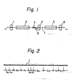
- Figure 1 is a diagrammatical elevational view illustrating an example of a process of the present invention for manufacturing a specially designed alternatingly twisted yarn
- Figure 2 is a model view illustrating a structure of a specially designed alternatingly twisted yarn obtained according to the present invention.
- Figures 3 through 11 are model views illustrating yarn forming mechanisms through which specially designed alternatingly twisted yarn according to the present invention are obtained.
- undetwisted portions which are obtained by retaining the twist structure, which has been in a yarn in a false twist imparting region while being subjected to false twisting are utilized as a compact twist yarn structure
- so called over detwisted portions which are obtained by detwisting a yarn in a false twist imparting region while being subjected to false twisting to an extent exceeding the twist density in the yarn, are utilized as a bulky twist yarn structure; and thus obtained alternatingly twisted yarn comprising the undetwisted portions and the over detwisted portions can result in a woven or knitted fabric having a handling similar to that obtained by a hard twist yarn or a true twist yarn due to the high twist density and a heather like feeling due to the difference in the configurations between the compact undetwisted portions and the over detwisted portions.
- the yarn does not have any uneveness in dyeability along the length thereof, and the requirement can be satisfied when false twisting is carried out under stationary conditions.
- the cohesion between the filaments constituting the yarn must be as little as possible. This requirement will be satisfied by not only appropriately selecting the false twisting conditions but also by utilizing an undrawn yarn, which has a wide temperature range wherein the filaments intermediately cohere, as a supply yarn, and selecting the molecular orientation in the undrawn supply yarn if necessary.
- conjugated fibers comprising at least two kinds of materials which are different in their melting points may be utilized, and at least two kinds of fibers which are different in their melting points and which are combined with each other may be utilized.
- polyester fibers may be effectively utilized.
- a friction type false twisting device must be used as a false twisting device, because such a twisting device imparts only small deflections except for twists into the yarn and does not create substantial ballooning in the yarn.
- the process of the present invention is capable of producing a multifilament yarn which is false twisted in such manner that the yarn alternatingly has compact twist yarn portions and bulky twist yarn portions along the length of the yarn, the twist directions of which are opposite to each other and the length of which are varied irregularly.
- compact twist yarn portion means a yarn portion which has twists and in which the crimp configuration of the filaments is consistent with the twist structure of the yarn.
- a compact twist yarn portion can be obtained.
- such a compactly twisted yarn portion is mainly obtained by retaining the twisting yarn structure, which has been in the yarn at a false twisting region while the yarn is false twisted, in the yarn which is obtained after the false twisting operation.
- bulk twist yarn portion means a yarn portion which has twists and in which the crimp configuration of the filaments appears.
- such bulky twist yarn portion can be obtained when a multifilament yarn which has no twist but has crimps therein is subjected to a twisting operation.
- such a bulky twist yarn portion is mainly adopted by an over detwisted yarn which is obtained by detwisting a yarn at a false twisting region under a false twisting operation over the twist density of the yarn.
- the yarn altematingly has compact twist yarn portions and bulky twist yarn portions
- the yarn does not substantially include any portions which are not included in either the compact undetwisted portions or the bulky detwisted portions.
- non-twisted portions which do not belong to either the compact undetwisted portions or the bulky over detwisted portions, at the boundaries between the compact untwisted portions and the bulky over detwisted portions.
- Such non-twisted portions do not have substantial length and usually do not exceed 1 mm.
- the relationship between the patterns with a heather like feeling in the obtained woven or knitted fabric and the amount of the undetwisted portions must be taken into consideration.
- the patterns are also related to the lengths of the undetwisted portions as well as the taste of the consumer; however, in general, if the amount of the undetwisted portions is small, only narrow stripe-like patterns appear on an obtained woven fabric; if the amount of the undetwisted portions exceeds 10%, the probability of undetwisted portions adjacent to each other becomes high and the width of the stripes increases, and therefore, the patterns clearly appear.
- the lengths and the amount of the undetwisted portions are simultaneously related to the patterns with a heather like feeling.
- the length of the undetwisted portions is about 5 mm
- uneven patterns appear but patterns with a heather like feeling cannot be obtained even if only the length of the undetwisted portions is about 10 mm, when the patterns are elongated from the uneven patterns.
- the area of the undetwisted portions increases, i.e., equal to or more than 30%
- patterns with a heather like feeling appear.
- the length of the undetwisted portions becomes about 40 mm
- patterns with a heather like feeling appear if there are about two undetwisted portions per one meter, i.e., about 8% of the total length.
- the sum of the squares of the lengths (in mm) of the undetwisted portions exceeds 3000 per one meter length of the yarn, patterns with a heather like feeling can be recognized.
- the yarn made by the process of the present invention has an additional characteristic in that it has at least a twist density (Turn/m) of 1.9x 10 3 ⁇ /D over the substantially entire yarn portions along the length of the yarn, wherein p is a specific gravity of the filaments and D is the denier number of the yarn.
- the yarn has a characteristic similar to that of a twisted yarn. More specifically, if a usual multifilament yarn or a false twisted yarn resulting therefrom is twisted, and if the relationship between the twist density and the handling is researched, a characteristic inherent to a twisted yarn can be recognized when the twist density exceeds a value of 1.9x10 3 Vp/D Turn/m.
- a yarn made by the present invention it is preferable for a yarn made by the present invention to have a tensile strength of at least 0.3 g/denier (0.27 g/dtex).
- the tensile strength of the yarn concerns the deformation of a yarn during a process wherein the yarn is formed into a woven fabric. It is preferable that the yarn has a high tensile strength in order to prevent the deformation of the yarn and that the yarn is subjected to the process under a low tension. If a yarn is subjected to the process under a tension of less than 0.27 g/dtex, the operability of the process and the quality of the obtained woven fabric will deteriorate, and accordingly, a tensile strength of at least 0.27 g/dtex is desirable. If a yarn is utilized after it is additionally twisted or sized so as to enhance the tensile strength, the original yarn is not required to have such a high tensile strength.
- a yarn has a tensile strength of at least 0.27 g/dtex as described above, after the yarn is stretch treated while being delivered between a pair of yarn feed rollers at a yarn speed of 200 m/min under a tension of 0.27 g/dtex, at least a part of compact twist yarn portions remain, and preferably 10% relative to the entire yarn length remain.
- the outer diameter of the bulky detwisted yarn portions is larger than the outer diameter of the compact undetwisted yarn portions by at least 10%, patterns with a heather like feeling appear clearly in a woven fabric resulting therefrom.
- the twist densities in the compact undetwisted portions and the bulky detwisted portions are higher, they are more preferable, however, the maximum degree of the twist densities is limited by means of the manner in which the devices are operated.
- the compactness of the undetwisted portions is enhanced and the bulkiness of the over detwisted portions is also enhanced.
- the compactness of the undetwisted portions can be obtained by retaining the twist structure in a yarn while being false twisted in a twist imparting region.
- the bulkiness of over detwisted portions can be obtained by increasing the crimps after cohesion between the constituent filaments is made as small as possible and crimps imparted to the constituent filaments are made to appear.
- the effect of the crimps must be large enough to exceed the negative effect resulting from twists.
- the twist density in a twist imparting region while a yarn is false twisted must be at least 17500 Vp/D Turn/m in order to obtain clear patterns with a heather like feeling in a woven or knitted fabric.
- Such a tendency may be enhanced when the twist density in a twist imparting region of the false twisting is high; and as a result of such tendency, the undetwisted portions may be cut into short portions, and accordingly, the length thereof may become short, and therefore, the total length thereof also may become short. Furthermore, this tendency results in a defect in that the twist density of the over detwisted portions cannot be enhanced.
- the twist density of a yarn located in a twist imparting region for false twisting can be retained in undetwisted portions without decreasing the density, and if false twisting is carried out under a high twist density, the total length of undetwisted portions with high twist density becomes remarkably long, and a yarn having over detwisted portions with high twist density can be obtained.
- the following features be included in the yarn in order to obtain a yarn with an enhanced twist density by retaining the twist structure of a yarn in a twist imparting region for false twisting so as to form compact undetwisted portions and form bulky excessively detwisted portions and not to form non-twisted portions as described above.
- a yarn, in a twist imparting region for false twisting, or undetwisted portions after the yamis false twisted, are detwisted, the entire twist density is not gradually decreased but only a part thereof-is detwisted, substantial remains at a constant level and the length thereof is gradually shortened.
- the portions which are detwisted are changed into over detwisted portions by absorbing the twists which depend on the twist density of the yarn before being detwisted.
- a yarn substantially does not have an uneveness in dyeability along the length of the yarn and that filaments constituting the yarn are almost not cohered to each other or the degree of the cohesion is so weak that filaments can be split without being cut, as would be the case if the filaments cohered to each other.
- a yarn made by the process of the present invention is further twisted, in general the following properties appear. More specifically, when the yarn is further twisted in a direction the same as that of the twists in the undetwisted portions, the undetwisted portions are unchanged and the twist density of the over detwisted portions is decreased. Contrary to this, when the yarn is further twisted in a direction the same as that of the twists in the over detwisted portions, the undetwisted portions become shortened while the twist density thereof is kept unchanged and the over detwisted portions are elongated while the twist density thereof is kept unchanged.
- the yarn made according to the present invention may be first further twisted in a direction the same as that of the over detwisted portions so that the area of the undetwisted portions is adjusted, and then, further twisted in a direction the same as that of the twists in the undetwisted portions so that the twist density of the undetwisted portions is adjusted to a value (Turn/m) of 1.9x 10 3 ⁇ /Dwhich is a minimum value for achieving the twist effect as described above, and the total length of the u ndetwisted portions and the twist effect are compared with each other, the existence of the undetwisted portions can acually be recognized if the amount of the undetwisted portions exceeds 10%.
- the lower limit of the undetwisted portions above which limit patterns with a heather like feeling clearly appear is 17500 Vp/D Turn/m.
- the lower limit of the over detwisted portions above which limit the twist effect can be recognized is 1.9x 10 3 v p/D Turn/m.
- the ratio of the total length of the undetwisted portions to the entire length of the yarn must be more than 10% and the ratio of the total length of the cover detwisted portions to the entire length of the yarn must be less than 90%.
- the twist density is undetwisted portions, the twist density in the over detwisted portions and the ratio of the length of the undetwisted portions to that of the over detwisted portions are of importance. It is obvious that if the twist densities are higher; the effect of handling due to the twist yarn becomes higher, however, it is necessary to create a remarkable effect of handling by means of the effect of the twist that the twist density in the undetwisted portions is at least 17500 ⁇ /D Turn/m, and that the ratio of the length of the undetwisted portions to the entire yarn length is at least 30% or/and that the twist density over substantially all the portions along the length of the yarn is at least 7500 Vp/D Turn/m. With regard to a yarn having a total twist of zero, all the requirements can be simultaneously satisfied.
- the twist density at the false twisted region is at least 22500 ⁇ /D Turn/m, the patterns can visually be recognized.
- the twist density in the undetwisted portions is approximately equal to that at the false twisted region (strictly speaking, in fact the former is slightly smaller than the latter, however, the difference can be disregarded), and due to false twisting with this twist density, crimps appear in the filaments in the over detwisted portions.
- a yarn having a total twist of zero if the undetwisted portions have the above-described twist density and they occupy a length of more than 30% in the entire yarn, the twist density of the over detwisted portions becomes equal to or more than a value of 9.5x 10 3 ⁇ /D Turn/m, and a yarn which has such a twist density generally belongs to a field having a handling obtained by a hard twist yarn rather than another field having a handling obtained by a usual twist yarn.
- the length of the undetwisted portions is in general determined by the various conditions for false twisting and can be varied by changing the conditions. If the sum of the squares of the length (mm) of the undetwisted portions per one meter of the yarn is at least 3000, more preferably at least 5000, very spectacular patterns with a heather like feeling can be obtained in combination with the above-explained twist effect. This is because, if the above requirement is satisfied, the length of the individual undetwisted portions is made long.
- an undrawn yarn is used as a supply yarn.
- Any friction type false twisting device may be used, however, it is preferable that a friction surface of the friction type false twisting device is moved in a direction intersecting with a yarn moving direction at an acute angle so that the yarn is subjected to the twisting operation simultaneously with the yarn delivering operation of the friction surface.
- the yarn passage especially a yarn passage located upstream from the false twisting device, or at least adjacent to the false twisting device, is made substantially stationary so that the ballooning of the yarn is substantially prevented from occurring, and the yarn is drawn and simultaneously or sequentially false twisted.
- the false twist number is in a range between a minimum value, which is a little bit higher than 17500 ⁇ /D Turn/m, and a maximum value, which is slightly smaller than a certain value of a false-twisting number which is usually used to obtain a usual false twisted yarn, i.e., a so called woolly yarn.
- a false twisting temperature increases, the effect becomes better, however, it is necessary to avoid such an excessively high temperature that filaments constituting the yarn and cohered to each other cannot be separated from each other unless the cohered filaments are broken.
- a yarn guide which is usually disposed downstream of a false twisting device in a conventional friction false twisting texturing machine, for example at a position of about 15 mm downstream from the lowermost friction disk in a friction type false twisting device of multiple friction disk type, is removed and under such a condition a yarn is textured.
- the false twisting conditions such as the removal of the yarn guide, the temperature condition of the false twisting heater, the false twist number and the draw ratio during the draw-false twisting, the twist densities of the undetwisted portions and the over detwisted portions and the lengths thereof can be varied to an extent which cannot be obtained through conventional methods.
- the false twist number must be at least 17500 p Turn/m as described above to produce a yarn having a handling similar to that obtained by a true twist yarn, and it must be at least 22500 ⁇ /D Turn/m to give a yarn having a handling similar to that obtained by a hard twist yarn.
- the temperature of the false twist heater is about between 210 and 240°C when a multifilament yarn made of polyester fibers is treated and if the temperature is about between 175 and 190°C when a multifilament yarn made of polyamide fibers, for example nylon 6 is treated.
- the temperature is set in accordance with the supply yarn, the desired textured yarn and the remaining texturing conditions.
- the formation of an alternatingly twisted yarn through a false twisting partly depends on the false twisting device and the upstream side thereof; however, the formation per se of an alternating twisted yarn is effected downstream of the false twisting device.
- a yarn located downstream of a false twisting device in a conventional method is observed, various conditions occur wherein undetwisted portions are formed, over detwisted portions are formed and non-twisted portions are formed.
- Undetwisted portions are formed through various methods which are classified into two cases, i.e., (1) a case wherein undetwisted portions which are being formed are rotated in a false twisting direction at a rotating speed depending upon the twist density, and (2) a case wherein they are rotated at a rotating speed lower than that of case (1) or are not rotated at all.
- the twist number upstream of the false twisting device is decreased.
- the formation of the over detwisted portions is followed by the increase of the twist number upstream of said false twisting device, and the non-twisted portions are formed as a transient phenomenon or are formed successively between the undetwisted portions and the excessively detwisted portions.
- the present invention is based on the knowledge that the formation of undetwisted portions just downstream of the false twisting device which can be occasionally observed in the above-described conventional methods is the most effective for forming the desired alternatingly twisted yarn, and according to the present invention, it is provided that such a formation is approximately always continued, and the twist condition of the undetwisted portion with rotation is brought to a condition similar to a false twisting condition upstream of the false twisting device. In other words, a condition wherein the false twist imparted region transmitted downstream of the false twisting device is always continued.
- the front end of the- false twist imparted region located downstream of the false twisting device is rotated, and the rotating portion untwists both the rear portion of the undetwisted portion which has been previously formed and the front end portion of itself so that excessively detwisted portions are successively formed, and-so that the front end of the false twist imparted region is moved downstream.
- the rotation of the front end of the false twist imparted region is stopped when it is held by means of delivery roller; when it contacts with a yarn guide or the like, or when the torque imparted by means of the false twisting device cannot. be transmitted.
- the false-twisting device continues to impart torque to the yarn, and therefore, a new detwisting point is created between the front end of the false twist imparted region and the false twisting device at each-moment
- the new detwisting point becomes a new front end of a new false twist imparted region, and accordingly, the above-mentioned phenomenon is repeated.
- the undetwisted portions and the over detwisted portions which are alternatingly distributed along the yarn, form an alternatingly twisted yarn Under the above-described mechanism for forming an alternatingly twisted yarn, any non-twisted portions are approximately not formed in fact.
- the main characteristics of a mechanismfor forming an alternatinglytwisted yarn according to the present invention are that, at least at a location just downstream of the false twisting device, a false twist imparting condition is always taking place, and that the rotation of the front end of the false twist imparted region is necessarily stopped by being held by means of a delivery roller, by being contacted with a guide or the like, or because the rotational force imparted by the false twisting device cannot be transmitted.
- the present invention there are three types of characteristic mechanisms for forming alternatingly twisted yarns based on the methods for stopping the rotation of the front end of the false twist imparted region, and the mechanisms respectively provide characteristic yarn.
- the front end is positively engaged with a member for preventing the transmission of the rotation of the yarn at the downstream side of the false twisting device, and at the same time, the number of the over detwisted portions generated between the false twisting device and the engaging member, is always one or less than one.
- the specially designed alternatingly twisted yarn is formed by always retaining a false twist imparting condition at the location just downstream of the false twisting device and by preventing the transmisssion of the rotation of the yarn downstream so that an over detwisted portion equal to or less than one is always formed between the false twisting device and the engaging member. That is, all various front ends of false twist imparted regions, which are generated as time passes, are made to arrive at the engaging member, such as the delivery roller or the guide, where the rotation of the front ends is stopped.
- FIG. 1 an example of a process according to the present invention for manufacturing a specially designed alternatingly twisted yarn is illustrated.
- a pair of feed rollers 1 feed a supply yarn to a pair of first delivery rollers 4 through a first heater device 2 and a false twisting device 3 which imparts twists into the supply yarn, and the twists imparted by means of the false twisting device 3 run back along the yarn to the heater device 2 where the twists are heat set.
- a second heater device 5 and a pair of second delivery rollers 6 are optionally disposed downstream of the first delivery rollers 4. Of course, in some cases, the second heater device 5 and the second delivery rollers 6 may be omitted.
- the member for preventing the transmission of the rotation of the yarn to the downstream may be the first delivery rollers 4; however instead, another engaging member 8 may be disposed at a location between the false twisting device 3 and the first delivery rollers 4 as illustrated by the broken lines.
- the member may be of a stationary type; however, it is preferable that a rotational member, for example a rotating guide which rotates as the engaged yarn moves, is disposed because such a member has a high effect for preventing the rotation of the yarn and has a low resistance against the movement of the yarn.
- a combination of a plurality of members may be utilized as the engaging member 8.
- the false twisting device 3 imparts a rotational force to the yarn, and therefore, the yarn located downstream of the false twisting device also has a tendency to rotate in a direction the same as that of the false twisting. Accordingly, it is probable that the yarn located downstream of the false twisting device is rotated and retains the false twist imparting condition while the false twists are not detwisted.
- a false twist imparting condition i.e., undetwisted condition, may receive a detwisting operation while the yarn is treated in the successive processes.
- a yarn made according to the present invention when its undetwisted portions are subjected to a detwisting operation, the entire twist density thereof is not gradually decreased but only a part of the undetwisted portion is untwisted, and the twist density in the undetwisted portion is substantially unchanged and the length thereof is gradually shortened, and the portions which have been untwisted absorb a lot of twists and change into over detwisted portions.
- the undetwisted portions have a coherently high compact portion with twist and high torsional rigidity, and once they are detwisted, they lose their cohesion and decrease their torsion rigidity.
- an appropriate fusing i.e., a part of or all the fusing in the undetwisted portions may be removed when they are subjected to detwisting. If a heating temperature is selected taking the material of the supply yarn and the material and quantity of the finishing, such as oil, into consideration, such fusing can be obtained.
- an engaging member such as the delivery roller or guide, for preventing the transmission of the rotation of the yarn to downstream is specially arranged at a location downstream from the false twisting device.
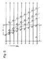
- FIGS 3,4,5 and 6 are model views illustrating mechanisms for forming alternatingly twisted yarns of this type as time elapses from to to to t" t 2 Vietnamese, in these figures, T denotes a stationary false twisting point; G, stationary point for preventing rotation by means of the engaging member; P, a boundary between the undetwisted portion and the over detwisted portion; and Q, a point where detwisting occurs.
- the length between the false twisting point T and the rotation preventing point G is denoted by L.
- Figures 3, 4, 5 and 6 a condition is assumed that at time to the front end P, of the false twist imparted region arrives at point G.
- the point P 3 moves downstream as the front end of a new false twist imparted region and arrives at point G (at time t 6 in Figure 3; time t 4 in Figure 4; time t 8 in Figure 5; and time t 3 in Figure 6), then a condition similar to that at time to appears.
- a new undetermined untwisting point Q 2 is formed and procedures similar to those described above are repeated.
- the total twist in both a yarn portion which is being treated and a yarn portion which is successive to the former yarn portion is constant and unchanged.
- the total twist in the yarn portion located upstream of the point T is constant if the false twisting is effected while stationary.
- the total twist in the yarn portion located downstream of the point P is unchanged and constant since the yarn portion has already been treated.
- the total twist between the point T and the point P is constant. More specifically,
- the equation (1) thus obtained means that the ratio between the length P 1 P 2 the undetwisted portion and the length P 2 P 3 of the over detwisted portion which is formed at a location upstream and adjacent thereto is determined by the twist densities and is constant.
- both cases illustrated in Figures 3 and 4 may occur, and besides, a case which is located at the intermediate of the cases illustrated in Figures 3 and 4 may also take place.
- detwisting may occur alternatingly at point P 2 and point P 3 ( Figure 5) or simultaneously at both points P 2 and P 3 ( Figure 6).
- the point Q may be formed at any point between the points T and G, I satisfies the following equation.
- an engaging member contacting only with yarn is disposed downstream of the false twisting device though, if it does not function well to prevent the downstream transmission of the rotation of the yarn, the mechanisms for forming alternatingly twisted yarns which were explained above with reference to Figures 3, 4, 5 and 6 cannot be achieved. Therefore, such an engaging member is not suitable, and a careful consideration concerning such point should be taken. In conclusion, even if an engaging member is disposed, the engaging member does not serve as a member for preventing the rotation of a yarn according to the present invention when it includes one or both of the following problems-
- thermoplastic synthetic multifilament yarn is subjected to a false twisting by means of a false twisting device, and after the yarn is passed through the false twisting device, the yarn is retained in a false twist imparted condition at a location at least adjacent to the false twisting device, the multifilament yarn is engaged with a member for preventing transmission of the rotation of the yarn disposed downstream of the false twisting device, wherein the member is arranged at such a location that the number of the over detwisted portions, which are generated between the false twisting device and the member for preventing the transmission of the rotation of the yarn is always at most one.
- a detwisting point Q when a detwisting point Q, is formed and a front end P 3 of the false twist imparted region is formed, only after the point P 3 arrives at the point G, a new detwisting point Q 2 is generated. More specifically if the distance L between the points T and G is set relatively short, the generation of a new Q 2 before the point P 3 arrives at the point G can be prevented from occurring.
- the length of the undetwisted portions are distributed between zero and L as explained above. If the above-explained embodiment is applied to an actual commercial process wherein a number of yarns are simultaneously manufactured, the distribution of the lengths of the compact undetwisted portions can be uniformalized between the yarns processed in different treating units.
- FIG. 2 A model view of a yarn made according to the present invention is illustrated in Figure 2, wherein if the length a i , denoting the length of either the undetwisted portion or the over detwisted portion, is long, the corresponding length b, is also long; and if the former a is short, correspondingly the latter b, is also short.
- the length which is the sum of a and b distributes randomly, and when a woven fabric is manufactured from such a yarn, the woven fabric can provide patterns which are uniformly distributed and have a slight heather like feeling.
- the structure of the yarn is characterized in that the yarn is a multifilament yarn and has false twisted crimps therein, and the Z-twist portion (or S-twist portion) is a compact twist yarn portion wherein the crimp configuration of the filaments is consistent with the twist structure of the yarn, and the S-twist portion (or Z-twist portion) is a bulky twist yarn portion wherein crimp configuration of the filaments appear in the twist structure of the yarn.
- portion of the S- or Z-portion may be used as a compact or bulky twist yarn portion, this can be selected by setting the false twisting direction at will, and the above explained relationships expressed in the equations can be applied to the portions.
- the length P 1 P 2 of the undetwisted portion formed between the points P, and P 2 and the length P 2 P 3 of the over detwisted portion formed between the points P 2 and P 3 always satisfy the equation (1).
- a specially designed alternatingly twisted yarn made by the present invention has: the length of undetwisted portions P 1 P 2 formed when the front end P 3 of the false twist imparted region arrived at the point G; and the length of an over detwisted portion P 1 P 3 formed adjacent to and upstream of the undetwisted portion.
- the lengths P 1 P 2 and P 1 P 3 satisfy the equation (1); however the length of the over detwisted portion does not have any predetermined relationship with the length of a undetwisted portion which is formed adjacent to and upstream of the excessively detwisted portion.
- an alternatingly twisted yarn of the present invention alternatingly has S-twist portions and Z-twist portions which vary in their lengths distributed along the length of the yarn, and there is a positive high correlation between lengths of the S-twist portion and the length of the Z-twist portion adjacent at one direction of the corresponding S-twist portion, but there is low correlation between the length of the S-twist portion and the length of the Z-twist portion adjacent at the opposite direction of the corresponding S-twist portion.
- a model view of a structure of an alternatingly twisted yarn made by the process of the present invention is exemplified in Figure 2.
- the term "positive high correlation” means that the correlation coefficient which will be defined below is at least 0.7, and the term “low correlation” means that the correlation coefficient is in a range between -0.3 and 0.3. More specifically the following equations (I) and (11) are satisfied.
- the number n used in the above equations (I) and (II) must be between 100 and 600.
- a process for manufacturing a specially designed alternatingly twisted yarn is characterized in that a thermoplastic synthetic multifilament yarn is subjected to false twisting by means of a false twisting device, and after the yarn is passed through the false twisting device, the yarn is retained in a false twist imparted condition at a location at least adjacent to the false twisting device, and in addition, an over detwisted portion always exists between the false twisting device and a member, which the yarn from the false twisting device contacts first.
- member which the yarn contacts first means a member, such as a delivery roller or a yarn guide utilized to change a yarn passage, which is similar to the member which was explained in connection with the first type mechanism and which was used to prevent the downstream transmission of the rotation of the yarn, and the term does not include a member which only contacts a yarn and which substantially does not have the function of preventing the transmission.
- FIGS 7, 8, 9 and 10 are model views illustrating mechanisms for forming alternatingly twisted yarns in the process of the present invention belonging to this type, wherein the changes are illustrated as time elapses from to to to t, and t 2 .
- T denotes a false twisting point
- G a contacting point where the yarn departing from the false twisting device contacts first
- P a boundary between a undetwisted portion and an over detwisted portion
- Q an untwisting commencing point.
- the points P, and Q are moved downstream at a speed equal to that of the yarn.
- the detwisted yarn portion changes into an excessively detwisted condition, and torque therein is balanced.
- Both ends of the over detwisted portion are denoted by P 2 and P 3 .
- the portion between the points P, and P z is moved downstream as an undetwisted portion, and the portion between the points P 2 and P 3 is moved downstream as an over detwisted portion while the length thereof increases.
- the point P 3 moves downstream as a front end of a new false twist imparted region, and finally it reaches an undetermined point Y where the rotational force imparted by the false twisting device cannot be transmitted downstream (at time t 2 in Figures 7 through 10), and then a condition similar to that at time to takes place, and procedure similar to that described above is repeated.
- detwisting occurs only at the point P 3 , and the over detwisted portion between the points P 2 and P 3 moves downstream while the length thereof is increased upstream.
- the point P 2 has a priority for detwisting at the first stage, and the over detwisted portion between the points P 2 and P 3 moves downstream while the length thereof is increased downstream.
- the detwisting does not occur at the point P 2 but at the point P 3 , i.e., a detwisting wherein the length thereof is increased upstream takes place.
- the number of the over detwisted portions located between T and G is one at times to and t 2 and is two at time t,. In this type of mechanism an over detwisted portion always exists between T and G.
- a yarn of the present invention can be obtained which has relatively long S-twist portions and Z-twist portions.
- the points X and Y, especially, detwisting commencing points Q, and Q 2 , in Figures 7 and 10 may be located at random between T and G, (more specifically, the point Q, may be located at random between X and T and the point Q 2 may be located randomly between Y and T), the lengths of the portions can be varied.
- a third type mechanism for forming alternatingly twisted yarn by the process of the present invention provides a method of manufacturing a specially designed alternatingly twisted yarn, in which relatively long undetwisted portions and over detwisted portions can be formed and in which, the coefficients of variation, i.e., the variations in the average lengths, of the undetwisted portions and the over detwisted portions can relatively be equalized even when many yarns are simultaneously manufactured by means of a multiplicity of yarn treating units in a machine. Accordingly, this type of mechanism is desirable for a commercial operation.
- the S- and Z-twists may not be diminished when the yarn is beaten, in other words, the S- and Z-twists in the yarn may probably remain, and accordingly, the obtained woven fabric can have a handling similar to that obtained by a hard twist yarn and patterns with a slight heather like feeling.
- a process for manufacturing an alternatingly twisted yarn of this type of the present invention has the following characteristics.
- a false twist imparted condition is always retained; and an engaging member is arranged close to the furthest downstream position which can be reached by this yarn portion retained in the false twist imparted condition while the yarn is being rotated (i.e., the ultimate position where the rotation of the yarn is stopped).
- case (1) wherein the furthest downstream end of the yarn in the false twist imparted condition arrives at the engaging member by which downstream transmission of the rotation of the yarn is prevented
- case (2) wherein the end does not arrive at the engaging member.
- both cases (1) and (2) occur randomly.
- a false twisting texturing machine having a construction similar to that illustrated in Figure 1 can be utilized to carry out the above-described process for manufacturing an atternatingty twisted yarn according to the present invention.
- the present mechanism for forming alternatingly twisted yarn comprises the procedure illustrated in Figure 3 through 6 concerning the first type mechanism and the procedure illustrated in Figures 7 through 10 regarding the second type mechanism, and these procedures occur randomly as time elapses.
- Figure 11 is a model view illustrating a mechanism of this type from time to to t, ... as time elapses.
- the front end P, of the false twist imparted region reaches the point G at time to.
- the portion located downstream of the point P is an over detwisted portion
- the portion located upstream of the point P is a false twist imparted region and is under undetwisted condition.
- a rotational force is applied at the point T, however, the point P, now located at the point G cannot rotate, and accordingly, detwisting is commenced at an undetermined point Q, located between the points T and P,.
- the points P, and Q advance downstream at a speed equal to that of the yarn.
- a yarn portion which has been detwisted is changed to an over detwisted condition, and the torque therein is balanced, and the both ends of the over detwisted portion are designated by P 2 and P 3 .
- the portion between the points P, and P 2 is a undetwisted portion and moves downstream, and the portion between the points P 2 and P 3 is an over detwisted portion and moves downstream while the length thereof is increased.
- the point P 3 moves downstream as a new front end of a new false twist imparted region, and finally arrives an undetermined point X where the rotation cannot be transmitted (at time t 2 ) so that a condition wherein the rotation cannot be transmitted similar to that at time to occurs. Accordingly, a new detwisting point Q 2 which is undetermined is formed, and then a procedure similar to that described above repeats.
- this mechanism is suitable to obtain an alternatingly twisted yarn by which a woven or knitted fabric having uniformly distributed patterns with a heather like feeling can be manufactured.
- a specially designed alternating twist yarn of the present invention has S-twist portions and Z-twist portions, the length of which are randomly distributed, and that the coefficient of variation, i.e., the variation of the lengths, is at least 50%.
- the coefficient of variation i.e., the variation of the lengths
- the requirements and conditions which are desirable to carry out a method of the present invention are not limited to the above-mentioned seven items, however, when a thermoplastic multifilament yarn is false twisted, if the above-mentioned seven items are satisfied, the object of the present invention can be achieved.
- Polyethylene terephthalate was melt spun and was taken up at a speed of 3000 m/min so that a multifilament yarn of 137 denier/36 filament was obtained.
- the yarn was drawn at a draw ratio of 1.4 and was false twisted at the drawing zone, the heating temperature was 238°C and the number of the false twists was 3200 Turn/m.
- the heating device was a contacting plate, the length of which was 1.5 m and the radius of curvature of which was 30 m, having a semi-circular groove, the radius of which was 2 mm and which extended along the yarn passage.
- the false twisting device was of an outer surface friction type provided with three shafts.
- the distance between the heating device and the false twisting device was 65 cm and a second contacting plate, the length of which was 50 cm, the radius of curvature of which was 10m, was disposed therebetween and was maintained at a temperature of 40°C.
- the distance between the false twisting device and the delivery device was 40 cm, and the delivery speed was 520 m/min.
- a rotatable guide having a diameter of 10 mm was disposed at a position 20 mm downstream of the false twisting device, and the yarn was wrapped therearound.
- a yarn alternatingly having undetwisted portions and over detwisted portions was obtained.
- the twist density of the undetwisted portions was 3000 Turn/m, the average length thereof was 8.3 mm, the maximum length thereof was 20 mm, and the ratio of the lengths thereof to the entire yarn length was 36.5%.
- the twist density of the over detwisted portions was 1720 Turn/m, the average length thereof was 14.4 mm, the maximum length.thereof was 32 mm, and the ratio of the lengths thereof to the entire yarn length was 63.5%.
- the correlation coefficient between the lengths of the undetwisted portions (a,) and the lengths of the over detwisted portions (b,) located adjacent thereto and downstream thereof during the treating operation was 0.14.
- the frequency between zero and 12.5 mm was almost constant, the frequency between 12.5 and 20 was gradually and linearly decreased as the length increased, and the length more than 20 mm was zero.
- the coefficient of variation of a was 60.0%.
- the outer diameter of the undetwisted portions was approximately uniform and was 100 ⁇ m, and the outer diameter of the over detwisted portions was 130 ⁇ m in their average.
- the yarn obtained through the above exptained process was further heat treated and then a woven fabric (structure: plain weave fabric; warp density: 87/inch (3425/m); and weft density: 84/inch (3300°/m) was manufactured.
- a woven fabric structure: plain weave fabric; warp density: 87/inch (3425/m); and weft density: 84/inch (3300°/m) was manufactured.
- the undetwisted portions were transparent and formed an ornamental effect in a combination of the warps and wefts, and the patterns were visually uniform.
- the fabric was hard due to the cohesion in the yarn and due to the hard twist effect, it was treated by means of caustic soda so that its weight was decreased by 23%, and a hand similar to that of cotton voile was obtained.
- the thus obtained fabric had an ornamental effect, which was superior to that obtained by a conventional yarn, and had a spectacular handling.
- Example 1 the rotational guide disposed downstream of the false twisting device and the engagement of the yarn therewith were changed as follows, and the other conditions were the same as those in Example 1.
- Test No. 1 The wrapping and contacting angle between the rotational guide and the yarn was set at 45°.
- Test No. 2 A second rotational guide similar to the rotational guide was disposed 14 mm downstream from the first rotational guide so that the yarn was passed along a zigzag (S-line) passage, and the contacting angle of each guide was 45°.
- the second rotational guide in test No. 2 did not contribute to prevent the rotation of the yarn, however, it served to change the yarn passage. Accordingly, such a rotational guide may be required in an actual process.
- Example 1 the location of the rotational guide is displaced to a position being 30 mm from and downstream of the false twisting device, and the other conditions were the same as those in Example 1.
- the twist density of the undetwisted portions in the obtained yarn was 3000 Turn/m, the average length thereof was 12.4 mm, and the maximum length thereof was 30 mm, and the ratio of the lengths thereof to the entire length of the yarn was 37.6%.
- the twist density of the over detwisted portions in the obtained yarn was 1810 Turn/m, the average length thereof was 20.6 mm, the maximum length thereof was 47 mm, and the ratio of the lengths thereof to the entire length of the yarn was 62.4%.
- Example 1 the rotational guide disposed at a position being 20 mm from and downstream of the false twisting device was replaced by a fixed guide made of titanium oxide ceramic and having a diameter of 8 mm, and the contacting angle of the yarn was 45°.
- the other conditions were the same as those in
- Example 1 A yarn approximately similar to that of Example 1 was obtained. More specifically, the over detwisted portions were slightly longer than those of Example 1, and the twist density thereof was a little bit lower than that of Example 1.
- 100 photographs of the yarn running between a location just downstream of the false twisting device and a location 5 mm downstream from the false twisting device were taken utilizing a stroboscope and then enlarged. In all 100 photographs, the yarn located just downstream from the false twisting device was in undetwisted condition. There were six photographs illustrating that over detwisted portions of 5 mm in length were included in the yarn.
- the obtained yarn alternatingly had undetwisted portions and over detwisted portions.
- the twist density of the undetwisted portions was 3000 Turn/m, the average length thereof was 70 mm, the maximum length thereof was 200 mm, the ratio of the lengths thereof to the entire length of the yarn was 39.4%, and outer diameter thereof was approximately 100 pm.
- the twist density of the over detwisted portions was 1950 Turn/m, the average length was 107.5 mm, the ratio of the lengths thereof to the entire yarn length was 60.6%, and the outer diameter thereof was 128 pm.
- the yarn obtained through the above explained process was subjected to a heat treatment by passing through a heating zone, which was disposed subsequent to the above-explained process, which was heated at a temperature of 237°C and the length of which was 1.2 m, and then it was taken up at a speed of 520 m/min so that the torque of the yarn was decreased and the tensile strength thereof was increased. Thereafter, a woven fabric (structure: plain weave fabric; warp density: 85/inch (3350/m); and weft density: 82/inch (3330/m) was obtained. In the thus obtained fabric, the undetwisted portions were transparent-like, and several undetwisted portions were continuously gathered on the fabric. The gathered undetwisted portions in the wefts and the warp form special patterns with a heather like feeling on the fabric. Although the fabric was partially not uniform and uneven, when it was visually observed as a whole, it felt uniform and had a spectacular ornamental appearance.
- a traverser was disposed at a position 50 mm upstream from the take up device so that the yarn engaging position in the take up device was varied and so that the take up device was protected. This traverser almost had no effect on the formation of the yarn.
- Example 5 the take up device positioned 40 cm downstream from the false twisting device along the rotational axis thereof was further displaced in a perpendicular direction by 5 cm, so that a yarn passed through the false twisting device was introduced along the rotational axis and was wrapped around a first rotational guide for 45°, and then was wrapped around a second rotational guide for 45° and introduced in the rotational axis, whereby the yarn was engaged with the take u p device.
- the other conditions were the same as those in Example 1.
- the distance L (mm) which was equal to the yarn passage between the false twisting device and the first rotational guide, was varied between 7 and 300 mm.
- the relationships between the distance and the average lengths and the maximum lengths of the undetwisted portions in the obtained yarns were researched.
- the average lengths were approximately proportional to the distance L if L was between 7 and 100 mm, and the average length was 40.5 mm for L equal to 100 mm.
- the degree of increase of the average length due to the increase of the distance L was gradually decreased, and the average length was almost constant, i.e., about 70 mm for the distance L of between 200 and 300 mm.
- the maximum length was approximately equal to L if L was between 7 and 200 mm. In a range wherein L was between 200 and 300 mm, the maximum length was about 200 mm and almost did not vary.
- Example 6 in addition to the temperature of 237°C for the false twisting machine, 235° and 240° were utilized, and the maximum arrival distances of the front ends of false.twist imparted region were measured. When the temperature was 235°C, the distance was 100 mm; and at 240°C, 250 mm.
- Example 5 under four conditions, wherein between a location 200 mm downstream from the false twisting device and the take up device, one fixed guide, two and three fixed guides, and one fixed guide and one rotational guide were disposed, the yarn engaging conditions were researched.
- the fixed guide can be used if the turning angle is equal to or less than 30°; and if the turning angle is more tHan 30°, the warapped contacting angle may be less than. 30° by utilizing a rotatable member.
- the obtained yarn had undetwisted portions and over detwisted portions which portions were alternatingly - distributed.
- the average lengths of the undetwisted portions were between 70 and 92 mm. These yarns were used as a weft yarn to form a plain weave fabric (warp yarn: a multifilament yarn of 50 denier/24 filament; warp density: 150/inch (5900/m); and weft density: 85/inch (3350/m)) a clear difference was felt between the part of the fabric wherein the yarn having an average length of undetwisted portions of 70 mm was-used and the part of the fabric wherein the yarn having an average length of 92 mm was used.
- warp yarn a multifilament yarn of 50 denier/24 filament; warp density: 150/inch (5900/m); and weft density: 85/inch (3350/m)
- a rotatable guide having a diameter of 10 mm was disposed at a location 160 mm downstream from the false twisting device, and the yarn was wrapped around this guide so that a treatment could be carried out.
- the average length of the undetwisted portions which had been 70 mm was changed to 62 mm, and similarly 92 mm was changed to 68 mm.
- These yarns were woven to form a plain weave fabric in which no substantial difference was visually recognized.
- the heating temperature in the treating unit, wherein the yarn having the longest average length of undetwisted portions was manufactured was 240°C, and contrary to this the heating temperature in the unit, wherein the yarn with the shortest average length was manufactured, was 237°C.
- the distance L (mm) which was measured along the yarn passage between the false twisting device and the rotatable guide was variously changed within a range of between 7 and 300 mm, and the relationship between the distance L, and the average length and the maximum length of undetwisted portions in the yarn obtained by the corresponding distance L was observed.
- the average lengths were approximately proportional to the distance L in a range wherein the distance L was 7 and 100 mm (7 and 120 mm), i.e., 4 0 .5 mm ( 5 1 mm) at L of 100 mm (120 mm).
- the degree of the increase of the average length was gradually decreased as the distance L increased, and when the distance L exceeded 200 mm (250 mm) until it reached 300 mm, the average length of about 70 mm (92 mm) was almost unchanged.
- the maximum length was approximately equal to L when the distance L was in a range between 7 and 200 mm (7 and 250 mm), and it was almost 200 mm (250 mm) and unchanged when the distance L was in a range of between 200 and 300 mm (250 and 300 mm).
Landscapes
- Engineering & Computer Science (AREA)
- Mechanical Engineering (AREA)
- Textile Engineering (AREA)
- Yarns And Mechanical Finishing Of Yarns Or Ropes (AREA)
Claims (17)
Priority Applications (2)
| Application Number | Priority Date | Filing Date | Title |
|---|---|---|---|
| DE8080304187T DE3071779D1 (en) | 1980-11-21 | 1980-11-21 | A process for manufacturing a textured multifilament yarn having alternating twists |
| EP19800304187 EP0052678B1 (de) | 1980-11-21 | 1980-11-21 | Verfahren zur Herstellung eines texturierten, alternierenden Drall aufweisenden Multifilamentgarn |
Applications Claiming Priority (1)
| Application Number | Priority Date | Filing Date | Title |
|---|---|---|---|
| EP19800304187 EP0052678B1 (de) | 1980-11-21 | 1980-11-21 | Verfahren zur Herstellung eines texturierten, alternierenden Drall aufweisenden Multifilamentgarn |
Publications (2)
| Publication Number | Publication Date |
|---|---|
| EP0052678A1 EP0052678A1 (de) | 1982-06-02 |
| EP0052678B1 true EP0052678B1 (de) | 1986-09-24 |
Family
ID=8187307
Family Applications (1)
| Application Number | Title | Priority Date | Filing Date |
|---|---|---|---|
| EP19800304187 Expired EP0052678B1 (de) | 1980-11-21 | 1980-11-21 | Verfahren zur Herstellung eines texturierten, alternierenden Drall aufweisenden Multifilamentgarn |
Country Status (2)
| Country | Link |
|---|---|
| EP (1) | EP0052678B1 (de) |
| DE (1) | DE3071779D1 (de) |
Families Citing this family (1)
| Publication number | Priority date | Publication date | Assignee | Title |
|---|---|---|---|---|
| CN118962087B (zh) * | 2024-10-14 | 2025-02-11 | 淄博尚和纺织有限公司 | 纱线捻度测试装置及测试方法 |
Family Cites Families (4)
| Publication number | Priority date | Publication date | Assignee | Title |
|---|---|---|---|---|
| GB815202A (en) * | 1956-08-04 | 1959-06-17 | Inventa Ag | Improvements relating to the production of crimped yarn of continuous filaments of synthetic linear polymers |
| GB1406421A (en) * | 1971-10-13 | 1975-09-17 | Ici Ltd | Production of bulked yarn |
| US3978647A (en) * | 1971-12-20 | 1976-09-07 | Mitsubishi Rayon Co., Ltd. | Highly coherent and rigid synthetic multifilamentary yarn and process for manufacturing the same |
| DE2831868C2 (de) * | 1978-07-20 | 1983-11-10 | Akzo Gmbh, 5600 Wuppertal | Verfahren zur Herstellung eines hochgezwirnten, abwechselnd S- und Z-Drehungen aufweisenden, synthetischen Filamentgarns mit Crêpegarn-Charakter |
-
1980
- 1980-11-21 EP EP19800304187 patent/EP0052678B1/de not_active Expired
- 1980-11-21 DE DE8080304187T patent/DE3071779D1/de not_active Expired
Also Published As
| Publication number | Publication date |
|---|---|
| EP0052678A1 (de) | 1982-06-02 |
| DE3071779D1 (en) | 1986-10-30 |
Similar Documents
| Publication | Publication Date | Title |
|---|---|---|
| US4307565A (en) | Spun yarn-like textured composite yarn and a process for manufacturing the same | |
| EP0044084B1 (de) | Einem gesponnenen Garn ähnliches, texturiertes Polyestergarn und Verfahren zu dessen Herstellung | |
| EP0022895B2 (de) | Baumwollgarnähnliches texturiertes Mischgarn und Verfahren zu dessen Herstellung | |
| US4402178A (en) | Textured multifilament yarn having alternating twists | |
| US4523428A (en) | Process for manufacturing textured multifilament yarn having alternating twist | |
| US4265082A (en) | Spun-like yarn and a process for manufacturing the same | |
| US4033103A (en) | Process and apparatus for producing a variable diameter alternate twist yarn | |
| US4103481A (en) | Variable diameter yarn | |
| US4345425A (en) | Process for making bulky textured multifilament yarn | |
| EP0052678B1 (de) | Verfahren zur Herstellung eines texturierten, alternierenden Drall aufweisenden Multifilamentgarn | |
| US4346552A (en) | Bulky textured multifilament yarn | |
| CA1135577A (en) | False twist machine | |
| CA1121674A (en) | Fabrics having salt-and-pepper patterns and crimped filament yarns for producing the same | |
| JPS6249376B2 (de) | ||
| JP2877817B2 (ja) | 嵩高フアンシーヤーンの製造方法 | |
| JPS5917209B2 (ja) | 特殊交互撚糸 | |
| JPS63105134A (ja) | スパンライク複合構造糸 | |
| JPH0317934B2 (de) | ||
| US3874156A (en) | Process for simultaneously edge-crimping and false-twisting yarn and yarn produced thereby | |
| JPS6142011B2 (de) | ||
| JPH1060745A (ja) | 嵩高弾性糸の製造方法 | |
| US4478037A (en) | Twisting method and apparatus | |
| JP4028153B2 (ja) | 仮撚加工糸及びその製造方法と同加工糸を用いた織編物並びに同加工糸を用いた合撚糸及び同合撚糸を用いた織編物 | |
| JP2004293006A (ja) | 仮撚加工糸及びその製造方法並びにその仮撚加工糸の合撚糸及び織編物 | |
| JP4077178B2 (ja) | 加工糸及びその織編物 |
Legal Events
| Date | Code | Title | Description |
|---|---|---|---|
| PUAI | Public reference made under article 153(3) epc to a published international application that has entered the european phase |
Free format text: ORIGINAL CODE: 0009012 |
|
| AK | Designated contracting states |
Designated state(s): DE FR GB IT NL |
|
| RBV | Designated contracting states (corrected) |
Designated state(s): DE FR GB IT NL |
|
| 17P | Request for examination filed |
Effective date: 19821020 |
|
| GRAA | (expected) grant |
Free format text: ORIGINAL CODE: 0009210 |
|
| ITF | It: translation for a ep patent filed | ||
| AK | Designated contracting states |
Kind code of ref document: B1 Designated state(s): DE FR GB IT NL |
|
| REF | Corresponds to: |
Ref document number: 3071779 Country of ref document: DE Date of ref document: 19861030 |
|
| ET | Fr: translation filed | ||
| PLBI | Opposition filed |
Free format text: ORIGINAL CODE: 0009260 |
|
| PLBI | Opposition filed |
Free format text: ORIGINAL CODE: 0009260 |
|
| PLBI | Opposition filed |
Free format text: ORIGINAL CODE: 0009260 |
|
| 26 | Opposition filed |
Opponent name: ENKA AG Effective date: 19870527 |
|
| NLR1 | Nl: opposition has been filed with the epo |
Opponent name: ENKA AG |
|
| 26 | Opposition filed |
Opponent name: RHODIA AG Effective date: 19870622 |
|
| NLR1 | Nl: opposition has been filed with the epo |
Opponent name: RHODIA AG |
|
| 26 | Opposition filed |
Opponent name: HOECHST AKTIENGESELLSCHAFT, FRANKFURT Effective date: 19870624 |
|
| NLR1 | Nl: opposition has been filed with the epo |
Opponent name: HOECHST AKTIENGESELLSCHAFT, |
|
| ITTA | It: last paid annual fee | ||
| PLAB | Opposition data, opponent's data or that of the opponent's representative modified |
Free format text: ORIGINAL CODE: 0009299OPPO |
|
| PGFP | Annual fee paid to national office [announced via postgrant information from national office to epo] |
Ref country code: FR Payment date: 19921109 Year of fee payment: 13 |
|
| PGFP | Annual fee paid to national office [announced via postgrant information from national office to epo] |
Ref country code: GB Payment date: 19921110 Year of fee payment: 13 |
|
| PGFP | Annual fee paid to national office [announced via postgrant information from national office to epo] |
Ref country code: NL Payment date: 19921130 Year of fee payment: 13 |
|
| R26 | Opposition filed (corrected) |
Opponent name: AKZO FASER AKTIENGESELLSCHAFT * 870622 RHONE-POULE Effective date: 19870527 |
|
| PGFP | Annual fee paid to national office [announced via postgrant information from national office to epo] |
Ref country code: DE Payment date: 19921212 Year of fee payment: 13 |
|
| NLXE | Nl: other communications concerning ep-patents (part 3 heading xe) |
Free format text: IN PAT.BUL.15/87 CORR.:AKZO FASER AKTIENGESELLSCHAFT + PAT.BUL.17/87 CORR.:RHONE-POULENC RHODIA AKTIENGESELLSCHAFT |
|
| RDAG | Patent revoked |
Free format text: ORIGINAL CODE: 0009271 |
|
| STAA | Information on the status of an ep patent application or granted ep patent |
Free format text: STATUS: PATENT REVOKED |
|
| 27W | Patent revoked |
Effective date: 19920730 |
|
| GBPR | Gb: patent revoked under art. 102 of the ep convention designating the uk as contracting state |
Free format text: 920730 |
|
| NLR2 | Nl: decision of opposition | ||
| APAH | Appeal reference modified |
Free format text: ORIGINAL CODE: EPIDOSCREFNO |