EP0052709B1 - Distributeur - Google Patents
Distributeur Download PDFInfo
- Publication number
- EP0052709B1 EP0052709B1 EP81107400A EP81107400A EP0052709B1 EP 0052709 B1 EP0052709 B1 EP 0052709B1 EP 81107400 A EP81107400 A EP 81107400A EP 81107400 A EP81107400 A EP 81107400A EP 0052709 B1 EP0052709 B1 EP 0052709B1
- Authority
- EP
- European Patent Office
- Prior art keywords
- pressure
- bore
- consumer
- annular groove
- housing
- Prior art date
- Legal status (The legal status is an assumption and is not a legal conclusion. Google has not performed a legal analysis and makes no representation as to the accuracy of the status listed.)
- Expired
Links
Images
Classifications
-
- F—MECHANICAL ENGINEERING; LIGHTING; HEATING; WEAPONS; BLASTING
- F15—FLUID-PRESSURE ACTUATORS; HYDRAULICS OR PNEUMATICS IN GENERAL
- F15B—SYSTEMS ACTING BY MEANS OF FLUIDS IN GENERAL; FLUID-PRESSURE ACTUATORS, e.g. SERVOMOTORS; DETAILS OF FLUID-PRESSURE SYSTEMS, NOT OTHERWISE PROVIDED FOR
- F15B13/00—Details of servomotor systems ; Valves for servomotor systems
- F15B13/14—Special measures for giving the operating person a "feeling" of the response of the actuated device
Definitions
- the invention is based on a directional valve according to the preamble of main claim 1.
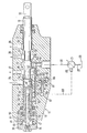
- a longitudinal bore 12 is formed in the housing 10 of a directional control valve 11, in which a control slide 13 is guided in a tightly sliding manner.
- annular grooves 14 to 18 are formed at a distance from one another, an inlet bore 19 running transversely to the longitudinal bore 12 opening into the annular groove 16, from which a delivery line 20 leads to a variable displacement pump 21.
- This sucks 22 pressure medium from a container 23 via a suction line.
- Such bores 27, 28, which open into the ring grooves 15, 17, have connection to a consumer, not shown.
- Two elongated annular grooves 31, 32 are formed on the control slide 13 on both sides of an approximately central collar 30.
- the control slide projects from one side of the housing and there has a connecting pin 33 which is articulated on a lever, not shown, via which the control slide is actuated.
- the housing is closed by an approximately screw-shaped locking screw 34, which is screwed into the housing.
- the control slide 13 has a central blind bore 36, into which a differential piston 37 is immersed, which is mounted in the base 38 of the screw plug slightly in the axial and radial directions, so that it can adjust itself correctly relative to the slide.
- the large-diameter piston part 37 ′ delimits the inner part of the blind bore 36, which forms a pressure chamber 39.
- a transverse bore 40 leads to a small annular groove 41 on the outside of the spool 13. From an annular groove 43 adjacent to the annular groove 41, also on the outside of the spool, a transverse bore 44 leads to a pressure chamber 45 formed by the differential piston 37 and the blind bore 36 .
- a sleeve 47 is screwed, which has an outer collar 48, on which the inner edge of a spring plate 49 rests, while the outer edge of which rests on the bottom 38 of the locking screw 34.
- a spring plate 49 Opposite the spring plate 49 there is also a spring plate 50 on the sleeve 47, the inner side of which rests against the end face of the control slide.
- a compression spring 51 which, together with the spring plates, forms a return device for the control slide 13 in a known manner, i.e. this places the spool in the neutral position shown in the drawing when no force is exerted on the spool.
- a channel 53 leads from the annular groove 14 into the region of the annular groove 41 when the control slide is in the neutral position.
- a channel 54 running in the housing 10 leads to a location on the longitudinal bore 12 that is close to the left flank 16 ′ of the annular groove 16.
- a third channel 55 in the housing likewise runs from the annular groove 43 to a point on the longitudinal bore 12 which is close to the right flank 16 "of the annular groove 16.
- a bore 56 branches off from the channel 55 and opens at the annular groove 41. From the channel 54, a channel 57 emerges, which opens into a housing bore 58 with two seats 59, 60 lying opposite one another.
- valve bodies 62, 63 of a double check valve 61 are arranged, which are pressed apart by a compression spring 64.
- a channel 65 running in the housing to the channel 55.
- a bore 66 leads from the center of the bore 58 to a bore 67 running transversely in the housing 10, from which a control line 68 leads to the pressure regulator 69 of the pump 21.
- the bore 67 will run through all valves, and from each such bore 67 a corresponding bore 66 leads to the double check valve 61.
- the pressure medium conveyed by the pump is passed on to the bore 28, from which it flows to the consumer.
- a certain load pressure builds up there, which is also propagated into the channel 55 via the annular groove 17. From here, the pressure medium reaches the annular grooves 41, 43 under this load pressure and from these in turn via the bores 40, 44 into the pressure chambers 39 and 45 on both sides of the piston 37 '.
- the highest pressure of the consumers connected to the valves is selected via the double check valves 61 and transmitted into the control line 68 via the bores 66, 67.
- the pressure prevailing there actuates the pressure regulator 69 of the pump 21 in such a way that the latter is set to the highest consumer pressure which arises.
Landscapes
- Engineering & Computer Science (AREA)
- Physics & Mathematics (AREA)
- Fluid Mechanics (AREA)
- Mechanical Engineering (AREA)
- General Engineering & Computer Science (AREA)
- Multiple-Way Valves (AREA)
- Sliding Valves (AREA)
Claims (5)
Applications Claiming Priority (2)
| Application Number | Priority Date | Filing Date | Title |
|---|---|---|---|
| DE19803044420 DE3044420A1 (de) | 1980-11-26 | 1980-11-26 | Wegeventil |
| DE3044420 | 1980-11-26 |
Publications (2)
| Publication Number | Publication Date |
|---|---|
| EP0052709A1 EP0052709A1 (fr) | 1982-06-02 |
| EP0052709B1 true EP0052709B1 (fr) | 1984-12-27 |
Family
ID=6117560
Family Applications (1)
| Application Number | Title | Priority Date | Filing Date |
|---|---|---|---|
| EP81107400A Expired EP0052709B1 (fr) | 1980-11-26 | 1981-09-18 | Distributeur |
Country Status (2)
| Country | Link |
|---|---|
| EP (1) | EP0052709B1 (fr) |
| DE (2) | DE3044420A1 (fr) |
Families Citing this family (4)
| Publication number | Priority date | Publication date | Assignee | Title |
|---|---|---|---|---|
| DE4325772C2 (de) * | 1993-07-31 | 1996-07-11 | Peter Dr Ing Beater | Antriebssystem mit einem Signalgeber |
| DE19631803B4 (de) * | 1996-08-07 | 2007-08-02 | Bosch Rexroth Aktiengesellschaft | Hydraulische Steuervorrichtung |
| DE19646449A1 (de) * | 1996-11-11 | 1998-05-14 | Rexroth Mannesmann Gmbh | Steuereinrichtung für einen hydraulischen Verbraucher, insbesondere für das Hubwerk eines Traktors |
| FR2860008B1 (fr) * | 2003-09-24 | 2006-02-10 | Staubli Sa Ets | Mecanisme de tirage a ratiere negative et metier a tisser equipe d'un tel mecanisme |
Family Cites Families (3)
| Publication number | Priority date | Publication date | Assignee | Title |
|---|---|---|---|---|
| GB796496A (en) * | 1954-11-02 | 1958-06-11 | British Messier Ltd | Improvements in or relating to fluid pressure servo mechanisms |
| US3152610A (en) * | 1961-09-11 | 1964-10-13 | New York Air Brake Co | Hydraulic device |
| DE1696047B2 (de) * | 1968-02-02 | 1976-12-02 | J. Walter Co, Maschinen Gmbh, 8640 Kronach | Hydraulisch oder pneumatisch angetriebene glaspresse |
-
1980
- 1980-11-26 DE DE19803044420 patent/DE3044420A1/de not_active Withdrawn
-
1981
- 1981-09-18 EP EP81107400A patent/EP0052709B1/fr not_active Expired
- 1981-09-18 DE DE8181107400T patent/DE3167960D1/de not_active Expired
Also Published As
| Publication number | Publication date |
|---|---|
| DE3167960D1 (en) | 1985-02-07 |
| DE3044420A1 (de) | 1982-06-16 |
| EP0052709A1 (fr) | 1982-06-02 |
Similar Documents
| Publication | Publication Date | Title |
|---|---|---|
| DE69019379T2 (de) | Kombiniertes lasthalt- und lastdruckkompensationsventil. | |
| DE2027562A1 (de) | Fluid-Steuervorrichtung | |
| DE1128239B (de) | Steuerschieber fuer doppeltwirkende druckmittelbetriebene Motoren | |
| DE2305798A1 (de) | Hydraulische steuereinrichtung, insbesondere lenkeinrichtung | |
| DE1959764A1 (de) | Druckkompensierte Steuerventile fuer durch ein Druckmedium betaetigte Systeme | |
| DE2232857C2 (de) | Steuereinrichtung für ein hydraulisch angetriebenes Arbeitsgerät | |
| DE2434229B2 (de) | Bremsdrucksteuereinheit für eine druckmittelbetätigbare Fahrzeugbremsanlage | |
| DE19631803B4 (de) | Hydraulische Steuervorrichtung | |
| DE1169746B (de) | Federbelastetes UEberdruckventil mit einem seine Ausloesung bewirkenden federbelasteten Hilfsventil | |
| DE4237932C2 (de) | Volumenstromsteuerung für Kraftfahrzeughydraulik, insbesondere für Lenkeinrichtungen von Kraftfahrzeugen | |
| DE2648280A1 (de) | Lastdrucksteuerung | |
| DE2359755C2 (de) | Hydraulisches Schaltventil | |
| EP0052709A1 (fr) | Distributeur | |
| DE19651967A1 (de) | Wegeventil zur lastunabhängigen Steuerung eines hydraulischen Verbrauchers hinsichtlich Richtung und Geschwindigkeit | |
| DE10135298A1 (de) | Ventilanordnung | |
| DE2701509A1 (de) | Hydraulische steuereinrichtung fuer wenigstens zwei verbraucher | |
| CH509535A (de) | Sicherheitsventil für druckmittelbetriebene Vorrichtungen | |
| DE2738463C2 (de) | Hydraulische Steuervorrichtung für einen bevorrechtigten zur Fahrzeuglenkung benützten ersten Servomotor und mindestens einen zweiten Servomotor | |
| DE4026849C2 (de) | Ventilanordnung zum Erzeugen eines Steuerdrucks in einer hydraulischen Anlage | |
| EP0877169B1 (fr) | Dispositif de commande hydraulique indépendante de la pression de charge d'un moteur à double effet | |
| DE3312511A1 (de) | Wegeventil mit steuerleitungen zum melden des verbraucherdruckes | |
| EP0258587B1 (fr) | Dispositif de commande hydraulique | |
| DE1284237B (de) | Steuereinrichtung mit einem Entlastungsventil und einem Antikavitations- oder Regulierventil | |
| DE3418172C2 (de) | Hydraulische Steuereinrichtung | |
| DE19625348A1 (de) | Anordnung zur Ansteuerung eines hydraulisch betätigbaren Hauptventils |
Legal Events
| Date | Code | Title | Description |
|---|---|---|---|
| PUAI | Public reference made under article 153(3) epc to a published international application that has entered the european phase |
Free format text: ORIGINAL CODE: 0009012 |
|
| 17P | Request for examination filed |
Effective date: 19810918 |
|
| AK | Designated contracting states |
Designated state(s): DE FR GB IT |
|
| ITF | It: translation for a ep patent filed | ||
| GRAA | (expected) grant |
Free format text: ORIGINAL CODE: 0009210 |
|
| AK | Designated contracting states |
Designated state(s): DE FR GB IT |
|
| REF | Corresponds to: |
Ref document number: 3167960 Country of ref document: DE Date of ref document: 19850207 |
|
| ET | Fr: translation filed | ||
| PLBE | No opposition filed within time limit |
Free format text: ORIGINAL CODE: 0009261 |
|
| STAA | Information on the status of an ep patent application or granted ep patent |
Free format text: STATUS: NO OPPOSITION FILED WITHIN TIME LIMIT |
|
| 26N | No opposition filed | ||
| PG25 | Lapsed in a contracting state [announced via postgrant information from national office to epo] |
Ref country code: GB Effective date: 19880918 |
|
| PG25 | Lapsed in a contracting state [announced via postgrant information from national office to epo] |
Ref country code: FR Free format text: LAPSE BECAUSE OF NON-PAYMENT OF DUE FEES Effective date: 19890531 |
|
| GBPC | Gb: european patent ceased through non-payment of renewal fee | ||
| PG25 | Lapsed in a contracting state [announced via postgrant information from national office to epo] |
Ref country code: DE Effective date: 19890601 |
|
| REG | Reference to a national code |
Ref country code: FR Ref legal event code: ST |