EP0052714A1 - Amplificateur de laser à excitation transverse - Google Patents
Amplificateur de laser à excitation transverse Download PDFInfo
- Publication number
- EP0052714A1 EP0052714A1 EP81107599A EP81107599A EP0052714A1 EP 0052714 A1 EP0052714 A1 EP 0052714A1 EP 81107599 A EP81107599 A EP 81107599A EP 81107599 A EP81107599 A EP 81107599A EP 0052714 A1 EP0052714 A1 EP 0052714A1
- Authority
- EP
- European Patent Office
- Prior art keywords
- housing
- electrodes
- laser amplifier
- amplifier according
- laser
- Prior art date
- Legal status (The legal status is an assumption and is not a legal conclusion. Google has not performed a legal analysis and makes no representation as to the accuracy of the status listed.)
- Granted
Links
Images


Classifications
-
- H—ELECTRICITY
- H01—ELECTRIC ELEMENTS
- H01S—DEVICES USING THE PROCESS OF LIGHT AMPLIFICATION BY STIMULATED EMISSION OF RADIATION [LASER] TO AMPLIFY OR GENERATE LIGHT; DEVICES USING STIMULATED EMISSION OF ELECTROMAGNETIC RADIATION IN WAVE RANGES OTHER THAN OPTICAL
- H01S3/00—Lasers, i.e. devices using stimulated emission of electromagnetic radiation in the infrared, visible or ultraviolet wave range
- H01S3/02—Constructional details
- H01S3/03—Constructional details of gas laser discharge tubes
-
- H—ELECTRICITY
- H01—ELECTRIC ELEMENTS
- H01S—DEVICES USING THE PROCESS OF LIGHT AMPLIFICATION BY STIMULATED EMISSION OF RADIATION [LASER] TO AMPLIFY OR GENERATE LIGHT; DEVICES USING STIMULATED EMISSION OF ELECTROMAGNETIC RADIATION IN WAVE RANGES OTHER THAN OPTICAL
- H01S3/00—Lasers, i.e. devices using stimulated emission of electromagnetic radiation in the infrared, visible or ultraviolet wave range
- H01S3/09—Processes or apparatus for excitation, e.g. pumping
- H01S3/097—Processes or apparatus for excitation, e.g. pumping by gas discharge of a gas laser
- H01S3/0971—Processes or apparatus for excitation, e.g. pumping by gas discharge of a gas laser transversely excited
Definitions
- the invention relates to a TE laser amplifier of essentially symmetrical construction with a symmetrical discharge current distribution, consisting of a gas-circulating electrode system having at least two opposite discharge surfaces, which is arranged with a high-voltage line leading to the outside in the resonator or discharge space of a housing, the in the case of laser operation, the laser beam has reflecting mirrors on its one end face in the direction of the other end face, which interact with partially transparent mirrors fastened in the region of this second end face, while in the case of amplifier operation, instead of the mirrors, the amplified laser radiation which passes through is provided, with mirrors and windows in the free spaces are arranged between the electrodes.
- Such laser amplifiers contain DE-OS 27 53 304 and European Patent 0 001 032. However, these otherwise usable laser amplifiers have a housing made of (glass) ceramic or quartz, which cannot be processed particularly well.
- GB-PS 1 301207 also shows and describes a similar laser.
- the object of the invention is to increase the service life and the power per volume for the generic laser amplifier. According to the invention, this object is achieved in that the housing is completely closed, e.g. from the outlet of the high-voltage supply and its insulator from the housing and up to the coupling or decoupling of the laser beam.
- Such metal housings can be easily manufactured for high pressures. On the other hand, you can achieve a homogeneous field distribution and good heat dissipation, which affects a longer life of the gas. Metal is also less gas permeable and easy to outgas.
- a metal housing is very stable and suitable for continuous operation.
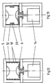
- FIG. 1 and 2 show the schematic diagram of an elongated TE laser amplifier 1, the housing 2 of which consists of a symmetrical hollow body made of metal, for example a non-magnetic metal such as aluminum, copper, tungsten, an alloy of these metals or a ferromagnetic metal.
- the hollow body essentially has the shape of a trough, in which an electrode 5 or 6 is fastened on the inside on the bottom side and on the cover 8 or is integrated into these walls.
- At least one further electrode 29 - in the present exemplary embodiment there are two - can be provided inside the gas space and outside the discharge zone.
- auxiliary electrode is then designed as a plate, (mesh) wire, film or pinhole and is guided outwards via an insulator 22 to one pole of the voltage source 30, for example a battery.
- the other pole of the voltage source lies on the housing 2.
- the high-voltage supply is designated by 11 and the part which isolates it and the electrode 5 from the rest of the housing * is designated by 12. But it would also be conceivable that the electrode 5 supplying the high-voltage pulse is freely suspended in the metallic housing 2.
- the actual gas discharge is carried out by methods known per se with the aid of trigger wires (according to Lambert-Pearson), so-called corona cutting, surface discharges or UV pre ionizations initiated or stabilized by spark gaps.
- the switching pulse required for this has a half width of typically ⁇ 100 nsec and a rising edge of typically ⁇ 20 nsec. This fast flank initiates the gas discharge due to the high voltage supplied via 11.
- the mirror 15 which reflects the radiation 100%, and on the right inner face 4, the mirror 16, which is partially transparent to the radiation, is attached to the left inner face 3 in the direction of view.
- the mirror 15 can also be designed as a triple, with the mirror and / or triple also being integrated into these end faces, if necessary, or being able to represent them themselves.
- Fig. 3 shows, in contrast, in the longitudinal axis of the housing 2, a central electrode 7, the discharge surfaces of the electrodes 5 and 6 facing with their white discharge surfaces 9, 10 in the opposite direction. It is of course conceivable here to carry out a single or multiple folding of the beam path, as a result of which a design which is short in accordance with the number of folds is achieved.
- the center electrode 7 is attached to the cover 8 and the electrodes 5 and 6 are attached to the side walls of the tub.
- the electrodes 5 and 6 are attached to the cover 8, while the central electrode - if any - is attached to the inner tub base or on one of the side walls or is integrated there.
- One of the electrodes must be insulated from the rest of the housing; in the present case it is the central electrode 7, with the help of the insulator 12 and 12 '.
- the isolator 12 ' could be omitted if the high-voltage supply 11 does not extend beyond the center electrode.
- Fig. 4 only shows a variant of Fig. 3, in which the insulator 12 and the cover 8 have been separated from one another Takes place.
- the high-voltage supply 11 and the center electrode 7 can also be made from one piece if necessary, as was indicated by the simple hatching of these parts in FIG. 3.
- a cooling device in the housing 2, which e.g. can also be connected to the resonator or discharge space 17 (FIG. 1) via a gas duct.
- Such training is then in the so-called flow operation and / or circulation process, which e.g. is described in DE-OS 27 53 304, operated.
- the lid is fastened with screws to the facing surfaces of the tub and sealed with an O-ring after the interior has been filled with gas using methods known from vacuum technology.
- Other locking options such as Gluing, soldering or electron welding are conceivable.
- housings with a round cross section are also conceivable.
- the plasma generated by the gas discharge is also influenced by the action on the magnetic and electrical field.
- the field lines emerge relatively widened in the initial region of the cathode 6, while after a polarity reversal of the excitation voltage shown in FIG. 6, the field lines emerge in a load parallel (homogeneous) manner.
- FIGS. 7 to 13 This effect can be supported by a whole number of measures indicated in FIGS. 7 to 13.
- the cross sections of anode 5 and cathode 6 being designed differently. Both have known profiles - e.g. Rogowski, Chang or others.
- Fig. 8 the cross section of the anode is smaller and in Fig. 9 larger than that of the respective. because associated cathode formed.
- two means for influencing the electrical potential profile are provided on the longitudinal walls of the housing.
- permanent or electromagnets 27, 28 are provided for this purpose.
- the direction of the field and the density can also be impressed on the field lines by forming the housing 2 which conducts the discharge current from magnetizable metal, for example according to FIGS.
- Both longitudinal walls of the housing 2 each have a constriction 18 running parallel to the electrodes 5 and 6, which e.g. in the case of FIG. 10 has an approximately semicircular cross section and is strictly limited to the area between the electrodes, which directly influences the stray fields.
- the constriction cross section is flatter and extends over the entire height of the wall.
- the electrodes can also have different cross sections.
- the mirrors 15 and 16 must be replaced by end windows which are transparent to the radiation. Immediately after the discharge taking place between the electrodes, a pulse is shot into the existing medium through one of these windows. This pulse usually has a nicer beam profile and a lower power. The total impulse then leaving the housing through the other window is amplified by approximately 3 to 10%.
Landscapes
- Physics & Mathematics (AREA)
- Electromagnetism (AREA)
- Engineering & Computer Science (AREA)
- Plasma & Fusion (AREA)
- Optics & Photonics (AREA)
- Lasers (AREA)
Applications Claiming Priority (2)
| Application Number | Priority Date | Filing Date | Title |
|---|---|---|---|
| DE3044023 | 1980-11-22 | ||
| DE3044023A DE3044023C2 (de) | 1980-11-22 | 1980-11-22 | Transversal angeregter Gaslaser-Oszillator oder -Verstärker |
Publications (3)
| Publication Number | Publication Date |
|---|---|
| EP0052714A1 true EP0052714A1 (fr) | 1982-06-02 |
| EP0052714B1 EP0052714B1 (fr) | 1984-12-27 |
| EP0052714B2 EP0052714B2 (fr) | 1988-03-16 |
Family
ID=6117322
Family Applications (1)
| Application Number | Title | Priority Date | Filing Date |
|---|---|---|---|
| EP81107599A Expired EP0052714B2 (fr) | 1980-11-22 | 1981-09-24 | Amplificateur de laser à excitation transverse |
Country Status (4)
| Country | Link |
|---|---|
| US (1) | US4677637A (fr) |
| EP (1) | EP0052714B2 (fr) |
| CA (1) | CA1172741A (fr) |
| DE (2) | DE3044023C2 (fr) |
Cited By (7)
| Publication number | Priority date | Publication date | Assignee | Title |
|---|---|---|---|---|
| FR2509096A1 (fr) * | 1981-07-03 | 1983-01-07 | Kraftwerk Union Ag | Laser a haute energie du type a excitation transversale |
| WO1984001672A1 (fr) * | 1982-10-14 | 1984-04-26 | Commw Of Australia | Laser a gaz excite par une decharge a haute pression |
| EP0247452A1 (fr) * | 1986-05-22 | 1987-12-02 | Siemens Aktiengesellschaft | Laser ionique |
| DE3817145A1 (de) * | 1987-06-03 | 1988-12-22 | Lambda Physik Forschung | Elektrode fuer gepulste gas-laser |
| EP0309825A1 (fr) * | 1987-09-24 | 1989-04-05 | Deutsches Zentrum für Luft- und Raumfahrt e.V. | Laser à gaz, notamment laser à haute puissance |
| EP0244474B1 (fr) * | 1985-11-12 | 1991-05-22 | Hughes Aircraft Company | Suppression de la decharge hf dans des dispositifs a gaz a basse pression |
| US6879616B2 (en) | 2003-01-24 | 2005-04-12 | Trumpf, Inc. | Diffusion-cooled laser system |
Families Citing this family (4)
| Publication number | Priority date | Publication date | Assignee | Title |
|---|---|---|---|---|
| JP2745776B2 (ja) * | 1990-05-10 | 1998-04-28 | 富士電機株式会社 | 燃料電池発電システム |
| US5557629A (en) * | 1992-08-28 | 1996-09-17 | Kabushiki Kaisha Komatsu Seisakusho | Laser device having an electrode with auxiliary conductor members |
| JP3787120B2 (ja) * | 2002-12-10 | 2006-06-21 | ファナック株式会社 | ガスレーザ発振装置 |
| US8258632B1 (en) * | 2005-10-24 | 2012-09-04 | Lawrence Livermore National Security, Llc | Optically-initiated silicon carbide high voltage switch with contoured-profile electrode interfaces |
Citations (3)
| Publication number | Priority date | Publication date | Assignee | Title |
|---|---|---|---|---|
| WO1979000432A1 (fr) * | 1977-12-23 | 1979-07-12 | Battelle Memorial Institute | Laser impulsionnel a milieu actif gazeux excite electriquement |
| GB2035674A (en) * | 1978-11-22 | 1980-06-18 | Eltro Gmbh | TEA laser apparatus |
| EP0024576B1 (fr) * | 1979-08-13 | 1984-07-25 | Kraftwerk Union Aktiengesellschaft | Dispositif pour la production de décharges pulsées rapides dans un laser, notamment pour des lasers à haute energie |
Family Cites Families (6)
| Publication number | Priority date | Publication date | Assignee | Title |
|---|---|---|---|---|
| DE147593C (fr) * | ||||
| US3638140A (en) * | 1969-07-28 | 1972-01-25 | Hughes Aircraft Co | Laser-cooling system |
| US3757248A (en) * | 1972-07-31 | 1973-09-04 | Massachusetts Inst Technology | Pulsed gas laser |
| US4150343A (en) * | 1975-01-10 | 1979-04-17 | Lasag Ag | Method for generating laser pulses by means of a gas laser and apparatus for carrying out the method |
| EP0001032B1 (fr) * | 1977-08-18 | 1981-02-25 | ELTRO GmbH Gesellschaft für Strahlungstechnik | Laser à décharge dans le gaz avec excitation transversale |
| DE2919709B2 (de) * | 1979-05-16 | 1981-03-12 | Opower, Hans, Dr., 8033 Krailling | Gepulster CO↓2↓-Laser |
-
1980
- 1980-11-22 DE DE3044023A patent/DE3044023C2/de not_active Expired
-
1981
- 1981-09-24 DE DE8181107599T patent/DE3167963D1/de not_active Expired
- 1981-09-24 EP EP81107599A patent/EP0052714B2/fr not_active Expired
- 1981-11-20 CA CA000390522A patent/CA1172741A/fr not_active Expired
-
1986
- 1986-02-20 US US06/833,502 patent/US4677637A/en not_active Expired - Fee Related
Patent Citations (3)
| Publication number | Priority date | Publication date | Assignee | Title |
|---|---|---|---|---|
| WO1979000432A1 (fr) * | 1977-12-23 | 1979-07-12 | Battelle Memorial Institute | Laser impulsionnel a milieu actif gazeux excite electriquement |
| GB2035674A (en) * | 1978-11-22 | 1980-06-18 | Eltro Gmbh | TEA laser apparatus |
| EP0024576B1 (fr) * | 1979-08-13 | 1984-07-25 | Kraftwerk Union Aktiengesellschaft | Dispositif pour la production de décharges pulsées rapides dans un laser, notamment pour des lasers à haute energie |
Cited By (7)
| Publication number | Priority date | Publication date | Assignee | Title |
|---|---|---|---|---|
| FR2509096A1 (fr) * | 1981-07-03 | 1983-01-07 | Kraftwerk Union Ag | Laser a haute energie du type a excitation transversale |
| WO1984001672A1 (fr) * | 1982-10-14 | 1984-04-26 | Commw Of Australia | Laser a gaz excite par une decharge a haute pression |
| EP0244474B1 (fr) * | 1985-11-12 | 1991-05-22 | Hughes Aircraft Company | Suppression de la decharge hf dans des dispositifs a gaz a basse pression |
| EP0247452A1 (fr) * | 1986-05-22 | 1987-12-02 | Siemens Aktiengesellschaft | Laser ionique |
| DE3817145A1 (de) * | 1987-06-03 | 1988-12-22 | Lambda Physik Forschung | Elektrode fuer gepulste gas-laser |
| EP0309825A1 (fr) * | 1987-09-24 | 1989-04-05 | Deutsches Zentrum für Luft- und Raumfahrt e.V. | Laser à gaz, notamment laser à haute puissance |
| US6879616B2 (en) | 2003-01-24 | 2005-04-12 | Trumpf, Inc. | Diffusion-cooled laser system |
Also Published As
| Publication number | Publication date |
|---|---|
| EP0052714B2 (fr) | 1988-03-16 |
| CA1172741A (fr) | 1984-08-14 |
| DE3167963D1 (de) | 1985-02-07 |
| US4677637A (en) | 1987-06-30 |
| DE3044023A1 (de) | 1982-06-03 |
| EP0052714B1 (fr) | 1984-12-27 |
| DE3044023C2 (de) | 1984-11-22 |
Similar Documents
| Publication | Publication Date | Title |
|---|---|---|
| DE4113241A1 (de) | Gepulster gasentladungslaser | |
| DE1000960B (de) | Vakuumpumpe | |
| DE2351919A1 (de) | Hohlkathoden-laserroehre | |
| EP0052714A1 (fr) | Amplificateur de laser à excitation transverse | |
| DE4108472A1 (de) | Vorrichtung zum vorionisieren von gas in einem gepulsten gaslaser | |
| EP0590346A1 (fr) | Laser à ruban à CO2 refroidi par diffusion avec tension d'allumage réduite | |
| EP0122597B1 (fr) | Laser à gaz à excitation transversale | |
| DE641080C (de) | Entladungsroehre, deren Wandung zwei oder mehrere leitende Teile aufweist | |
| DE2546512B2 (de) | Hochleistungs-gaslaser | |
| DE2224008B2 (de) | Gas-Laser | |
| EP0001032B1 (fr) | Laser à décharge dans le gaz avec excitation transversale | |
| DE2048862C3 (de) | Vorrichtung zur spektralphotometrischen Analyse | |
| DE3212705C2 (fr) | ||
| DE2060948A1 (de) | Gaslaser | |
| DE2527609C3 (de) | Ionenquelle | |
| DE3588137T2 (de) | Entladungsangeregtes Lasergerät | |
| DE3851515T2 (de) | Metalldampf-Laser-Apparat. | |
| EP1218975B1 (fr) | Laser a gaz | |
| DE3611303A1 (de) | Gaslaseranordnung | |
| EP0610170B1 (fr) | Laser à gaz | |
| DE10010706A1 (de) | Hohlkathoden-Sputter-Ionenquelle zur Erzeugung von Ionenstrahlen hoher Intensität | |
| DE3035702A1 (de) | Vorionisierungs-anordnung fuer tea-laser, insbesondere tea-excimmer-laser | |
| DE3816413A1 (de) | Verfahren zum betreiben eines gasentladungslasers und gasentladungslaser | |
| DE2908350A1 (de) | Glimmentladungslampe zur qualitativen und quantitativen spektralanalyse | |
| DE1931391C (de) | Optischer Sender oder Verstarker fur kohärente Strahlung |
Legal Events
| Date | Code | Title | Description |
|---|---|---|---|
| PUAI | Public reference made under article 153(3) epc to a published international application that has entered the european phase |
Free format text: ORIGINAL CODE: 0009012 |
|
| AK | Designated contracting states |
Designated state(s): BE CH DE FR GB IT NL |
|
| 17P | Request for examination filed |
Effective date: 19820528 |
|
| ITF | It: translation for a ep patent filed | ||
| GRAA | (expected) grant |
Free format text: ORIGINAL CODE: 0009210 |
|
| AK | Designated contracting states |
Designated state(s): BE CH DE FR GB IT LI NL |
|
| REF | Corresponds to: |
Ref document number: 3167963 Country of ref document: DE Date of ref document: 19850207 |
|
| ET | Fr: translation filed | ||
| PLBI | Opposition filed |
Free format text: ORIGINAL CODE: 0009260 |
|
| 26 | Opposition filed |
Opponent name: KRAFTWERK UNION AKTIENGESELLSCHAFT Effective date: 19850927 |
|
| NLR1 | Nl: opposition has been filed with the epo |
Opponent name: KRAFTWERK UNION AKTIENGESELLSCHAFT |
|
| PLAB | Opposition data, opponent's data or that of the opponent's representative modified |
Free format text: ORIGINAL CODE: 0009299OPPO |
|
| R26 | Opposition filed (corrected) |
Opponent name: DELETED BERGES, PIETER JOZEF R. 106(3), 102(1) 24. Effective date: 19850927 |
|
| PLAB | Opposition data, opponent's data or that of the opponent's representative modified |
Free format text: ORIGINAL CODE: 0009299OPPO |
|
| PUAH | Patent maintained in amended form |
Free format text: ORIGINAL CODE: 0009272 |
|
| STAA | Information on the status of an ep patent application or granted ep patent |
Free format text: STATUS: PATENT MAINTAINED AS AMENDED |
|
| 27A | Patent maintained in amended form |
Effective date: 19880316 |
|
| AK | Designated contracting states |
Kind code of ref document: B2 Designated state(s): BE CH DE FR GB IT NL |
|
| NLXE | Nl: other communications concerning ep-patents (part 3 heading xe) |
Free format text: IN PAT.BUL.02/86,PAGE 273:CORR.:SIEMENS AG |
|
| R26 | Opposition filed (corrected) |
Opponent name: SIEMENS AKTIENGESELLSCHAFT, BERLIN UND MUENCHEN Effective date: 19850927 |
|
| NLR2 | Nl: decision of opposition | ||
| NLR3 | Nl: receipt of modified translations in the netherlands language after an opposition procedure | ||
| EN3 | Fr: translation not filed ** decision concerning opposition | ||
| ITTA | It: last paid annual fee | ||
| PGFP | Annual fee paid to national office [announced via postgrant information from national office to epo] |
Ref country code: NL Payment date: 19890930 Year of fee payment: 9 |
|
| PG25 | Lapsed in a contracting state [announced via postgrant information from national office to epo] |
Ref country code: NL Effective date: 19910401 |
|
| NLV4 | Nl: lapsed or anulled due to non-payment of the annual fee | ||
| PGFP | Annual fee paid to national office [announced via postgrant information from national office to epo] |
Ref country code: GB Payment date: 19910718 Year of fee payment: 11 |
|
| PGFP | Annual fee paid to national office [announced via postgrant information from national office to epo] |
Ref country code: CH Payment date: 19910813 Year of fee payment: 11 |
|
| PGFP | Annual fee paid to national office [announced via postgrant information from national office to epo] |
Ref country code: BE Payment date: 19911024 Year of fee payment: 11 |
|
| PGFP | Annual fee paid to national office [announced via postgrant information from national office to epo] |
Ref country code: DE Payment date: 19920909 Year of fee payment: 12 |
|
| PG25 | Lapsed in a contracting state [announced via postgrant information from national office to epo] |
Ref country code: GB Effective date: 19920924 |
|
| PG25 | Lapsed in a contracting state [announced via postgrant information from national office to epo] |
Ref country code: LI Effective date: 19920930 Ref country code: CH Effective date: 19920930 Ref country code: BE Effective date: 19920930 |
|
| BERE | Be: lapsed |
Owner name: ELTRO G.M.B.H. G. FUR STRAHLUNGSTECHNIK Effective date: 19920930 |
|
| GBPC | Gb: european patent ceased through non-payment of renewal fee |
Effective date: 19920924 |
|
| REG | Reference to a national code |
Ref country code: CH Ref legal event code: PL |
|
| PGFP | Annual fee paid to national office [announced via postgrant information from national office to epo] |
Ref country code: FR Payment date: 19930909 Year of fee payment: 13 |
|
| PG25 | Lapsed in a contracting state [announced via postgrant information from national office to epo] |
Ref country code: DE Effective date: 19940601 |
|
| PG25 | Lapsed in a contracting state [announced via postgrant information from national office to epo] |
Ref country code: FR Effective date: 19950531 |
|
| REG | Reference to a national code |
Ref country code: FR Ref legal event code: ST |