EP0052726B1 - Récipient isolant pour aliments - Google Patents
Récipient isolant pour aliments Download PDFInfo
- Publication number
- EP0052726B1 EP0052726B1 EP81107978A EP81107978A EP0052726B1 EP 0052726 B1 EP0052726 B1 EP 0052726B1 EP 81107978 A EP81107978 A EP 81107978A EP 81107978 A EP81107978 A EP 81107978A EP 0052726 B1 EP0052726 B1 EP 0052726B1
- Authority
- EP
- European Patent Office
- Prior art keywords
- sealing
- webs
- jacketing
- insert
- lid
- Prior art date
- Legal status (The legal status is an assumption and is not a legal conclusion. Google has not performed a legal analysis and makes no representation as to the accuracy of the status listed.)
- Expired
Links
- 235000013305 food Nutrition 0.000 title claims abstract description 11
- 238000007789 sealing Methods 0.000 claims abstract description 16
- 239000011521 glass Substances 0.000 claims description 7
- 229920003023 plastic Polymers 0.000 claims description 5
- 239000004033 plastic Substances 0.000 claims description 5
- 230000002093 peripheral effect Effects 0.000 claims description 3
- 230000000875 corresponding effect Effects 0.000 claims 3
- 238000005253 cladding Methods 0.000 abstract 1
- 238000004519 manufacturing process Methods 0.000 description 7
- 238000010276 construction Methods 0.000 description 4
- 238000005516 engineering process Methods 0.000 description 2
- 206010053648 Vascular occlusion Diseases 0.000 description 1
- 238000004026 adhesive bonding Methods 0.000 description 1
- 238000005187 foaming Methods 0.000 description 1
- 238000002347 injection Methods 0.000 description 1
- 239000007924 injection Substances 0.000 description 1
- 238000009434 installation Methods 0.000 description 1
- 238000009413 insulation Methods 0.000 description 1
- 239000002184 metal Substances 0.000 description 1
- 235000021178 picnic Nutrition 0.000 description 1
- 230000001681 protective effect Effects 0.000 description 1
- 230000000630 rising effect Effects 0.000 description 1
- 230000002792 vascular Effects 0.000 description 1
- 208000021331 vascular occlusion disease Diseases 0.000 description 1
- 238000003466 welding Methods 0.000 description 1
Images


Classifications
-
- A—HUMAN NECESSITIES
- A47—FURNITURE; DOMESTIC ARTICLES OR APPLIANCES; COFFEE MILLS; SPICE MILLS; SUCTION CLEANERS IN GENERAL
- A47J—KITCHEN EQUIPMENT; COFFEE MILLS; SPICE MILLS; APPARATUS FOR MAKING BEVERAGES
- A47J41/00—Thermally-insulated vessels, e.g. flasks, jugs, jars
- A47J41/0055—Constructional details of the elements forming the thermal insulation
- A47J41/0072—Double walled vessels comprising a single insulating layer between inner and outer walls
- A47J41/0077—Double walled vessels comprising a single insulating layer between inner and outer walls made of two vessels inserted in each other
Definitions
- the invention relates to a feed vessel designed as an insulating vessel according to the preamble of claim 1.
- the heat-insulating inner container consists of a double-walled, evacuated and possibly internally mirrored glass body.
- the inner container is therefore relatively susceptible to mechanical damage, in particular when used in a food container of the type mentioned above, when eating directly from the food container with metal cutlery. It has therefore become common practice to provide a plastic inner insert which rests against its inner wall and protects it in such feed vessels in order to protect the inner container.
- Such containers are known for example from DE-B-1212696 and DE-U-7331 929.
- the sensitive inner container between the casing body and the inner insert must be enclosed and held as tightly and reliably as possible, manufacturing technical care is required to achieve this holding enclosure.
- a partial one-piece construction between the inner insert and the casing body is proposed in the second prior art document, which leads to a relatively complex and bulky plastic injection-molded part.
- the inner container overlaps the insulating container at the top, then forms part of the outer casing, and is then screwed to the casing part.
- the sensitive glass insulated container is supported on a rigid nozzle rising from the floor. It is therefore also at risk when the jacket and inner container are screwed together.
- welding or gluing is proposed for the connection between the inner insert and the casing body, which is complex in terms of production technology and requires care in mass production.
- This part which is generally designed as a screw cap and has a handle in the case of receptacles, must have a sealing part which seals the inside opening of the receptacle in a well-sealed manner.
- an elastic protective sleeve is provided on the bottom of the jacket to support the glass insulating vessel. This can yield in a certain range, but this arrangement also requires great care when screwing the bottom and jacket together.
- the sensitive insulating vessel is clamped and endangered in the same way.
- the handle protruding laterally from the jacket or lid is designed to hold cutlery items.
- the jacket and inner part or bottom are connected by means of thread arrangements, the closure is screwed into the inner part by means of a thread or is inserted by means of a bayonet arrangement.
- Bayonet connections are also used to insert sealing plugs in insulating containers (US-A-2 925 187).
- wedge-like projections are provided on the part and corresponding grooves are provided on the other part, so that during assembly these parts interlock or there are pegs projecting upwards on the inner part arranged, which engage in corresponding vertical bores in a radially inwardly projecting flange of the upper part of the shell during assembly.
- great care must be taken to ensure that the keyway and tenon-and-hole connections are perfectly aligned when the snap connection is made. Installation with these guide means is time-consuming and cumbersome and can only be mechanized by complex control measures.
- the invention has for its object to construct the individual parts accommodating the inner container in such a way that they can be assembled in production terms without additional tools or devices with little work on the conveyor belt to form the finished feed vessel.
- the feed vessel consists of a heat-insulating inner container 1, which consists, for example, of a double-walled, evacuated glass container.
- the melted evacuation nozzle is designated by 2.
- the inner container 1 is surrounded by a jacket body 3, which consists of a jacket part 4 with a side handle 5 and a bottom part 6. From the inside of the bottom part 6 there are elastic webs 7, which are arranged in a circle according to FIG. 2, approximately like a petal, and support the inner container 1. 1, a second size of the inner container, which lies within the tolerance, is indicated by dashed lines, the elastic webs 7 then occupying the position also indicated by dashed lines.
- An inner insert 8 is arranged inside the inner container 1 and is connected to the casing body 3 by means of a latching construction, which is denoted overall by 9.
- the inner insert 8 extends outwards over the upper edge of the inner container 1 and has a thread 10 on the outside, onto which a vascular closure, generally designated 11, can be screwed.
- the vessel closure 11 consists of a cover part 12 with a carrying handle 13, in which a sealing part 14 is inserted via a latching structure, designated overall by 15.
- the sealing part 14 seals the upper opening of the inner insert with the inner container in the scrubbed state of the vessel closure 11.
- the carrying handle 5 on the outside of the jacket part 4 has in its upper web 16 an opening 16 'into which a piece of cutlery can be inserted.
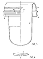
- Each latch construction consists of a combined rotary latch and an axial pull latch. 2, on the inside of the jacket part 4 of the jacket body 3 projecting circumferential webs 17 are provided as the axial pull latching of the latching construction 9, which in the assembled state cooperate with circumferential webs 18 on the inner insert 8 according to FIG. 3.
- a number of projecting, axially extending webs 19 are arranged over an inner cylindrical jacket region of the jacket part 4, which engage in recesses 20 according to FIGS. 3 and 4 when the peripheral webs 17, 18 are connected.
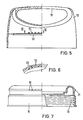
- 5 and 7 consists of a projecting web 21 which extends in the circumferential direction and which can extend over the entire circumference or only partially over the circumference, the web 21 behind the over the Internally distributed projections 22 of the cover part 12 snaps into place.
- projecting webs 23 are provided as a rotary catch, which engage in recesses 24 on the circumference of the sealing part 14.
Landscapes
- Physics & Mathematics (AREA)
- Thermal Sciences (AREA)
- Engineering & Computer Science (AREA)
- Food Science & Technology (AREA)
- Packages (AREA)
- Table Devices Or Equipment (AREA)
- Purses, Travelling Bags, Baskets, Or Suitcases (AREA)
- Closures For Containers (AREA)
Claims (5)
Priority Applications (1)
| Application Number | Priority Date | Filing Date | Title |
|---|---|---|---|
| AT81107978T ATE11633T1 (de) | 1980-11-20 | 1981-10-06 | Als isoliergefaess ausgebildetes speisegefaess. |
Applications Claiming Priority (2)
| Application Number | Priority Date | Filing Date | Title |
|---|---|---|---|
| DE3043826 | 1980-11-20 | ||
| DE19803043826 DE3043826A1 (de) | 1980-11-20 | 1980-11-20 | Als isoliergefaess ausgebildetes speisegefaess |
Publications (2)
| Publication Number | Publication Date |
|---|---|
| EP0052726A1 EP0052726A1 (fr) | 1982-06-02 |
| EP0052726B1 true EP0052726B1 (fr) | 1985-02-06 |
Family
ID=6117225
Family Applications (1)
| Application Number | Title | Priority Date | Filing Date |
|---|---|---|---|
| EP81107978A Expired EP0052726B1 (fr) | 1980-11-20 | 1981-10-06 | Récipient isolant pour aliments |
Country Status (4)
| Country | Link |
|---|---|
| US (1) | US4473161A (fr) |
| EP (1) | EP0052726B1 (fr) |
| AT (1) | ATE11633T1 (fr) |
| DE (2) | DE3043826A1 (fr) |
Cited By (1)
| Publication number | Priority date | Publication date | Assignee | Title |
|---|---|---|---|---|
| US6652923B2 (en) | 2000-02-16 | 2003-11-25 | Ise Electronics Corporation | Electron-emitting source, electron-emitting module, and method of manufacturing electron-emitting source |
Families Citing this family (15)
| Publication number | Priority date | Publication date | Assignee | Title |
|---|---|---|---|---|
| DE8334684U1 (de) * | 1983-12-02 | 1984-01-26 | Rotpunkt Dr. Anso Zimmermann, 6434 Niederaula | Isolierflasche fuer Fluessigkeiten |
| US5553735A (en) * | 1994-03-08 | 1996-09-10 | Kimura; Fumiyo | Vessel with display function |
| DE9420827U1 (de) * | 1994-12-28 | 1996-05-02 | Emsa-Werke Wulf GmbH & Co, 48282 Emsdetten | Thermokanne |
| DE19622956C2 (de) * | 1996-04-06 | 2001-05-03 | Milke Siegfried | Isolierkanne und Deckel |
| US5918761A (en) * | 1996-11-06 | 1999-07-06 | The Thermos Company | Vacuum insulated travel mug |
| US5950854A (en) * | 1997-09-30 | 1999-09-14 | Genpak, L.L.C. | Container closure system |
| US5968618A (en) * | 1998-04-13 | 1999-10-19 | Miller; Blair J. | Thermal coffee carafe |
| DE29819515U1 (de) * | 1998-11-02 | 1999-01-07 | Ewald Euscher GmbH & Co, 33611 Bielefeld | Sprühdose |
| US6105799A (en) * | 1999-01-02 | 2000-08-22 | Takagawa; Nobuyuki | Thermal container having improved supporting units therein to securely hold the insulated vessel within the outer structure thereof |
| US6354452B1 (en) * | 2000-07-25 | 2002-03-12 | Becton, Dickinson And Company | Collection container assembly |
| US6386431B1 (en) * | 2001-01-19 | 2002-05-14 | Shin-Shuoh Lin | Vacuum insulated coffee server manufacturing process |
| AU2003268274A1 (en) * | 2002-09-04 | 2004-03-29 | Becton, Dickinson And Company | Collection assembly |
| US20090071968A1 (en) * | 2007-09-11 | 2009-03-19 | O'brien Diane | Container |
| US20090107997A1 (en) * | 2007-10-30 | 2009-04-30 | Cornelius Derek W | Leak-proof drinking cup and lid assembly |
| US20090266737A1 (en) * | 2008-04-23 | 2009-10-29 | Cole Joseph W | Beverage container permitting multiple configurations |
Family Cites Families (20)
| Publication number | Priority date | Publication date | Assignee | Title |
|---|---|---|---|---|
| CA848254A (en) * | 1970-08-04 | Veb Rhonglaswerk Dermbach | Insulated food and beverage container | |
| GB640056A (en) * | 1947-12-23 | 1950-07-12 | Thermos 1925 Ltd | Improvements in or relating to vacuum flasks |
| US2925187A (en) * | 1956-12-03 | 1960-02-16 | Aladdin Ind Inc | Closures for vacuum bottles |
| US2934231A (en) * | 1958-02-13 | 1960-04-26 | Aladdin Ind Inc | Closure for vacuum bottles |
| DE1212696B (de) * | 1959-06-16 | 1966-03-17 | Aladdin Ind Inc | Isolierbehaelter |
| DE1811516U (de) * | 1959-12-22 | 1960-05-19 | Glashuette Ing A Ritschny | Isoliergefaess. |
| US3232468A (en) * | 1963-08-05 | 1966-02-01 | Aladdin Ind Inc | Vacuum bottles having plastic liner |
| DE1429786A1 (de) * | 1963-08-05 | 1969-02-06 | Aladdin Ind Inc | Thermosflasche |
| US3298554A (en) * | 1963-09-11 | 1967-01-17 | Hamilton Skotch Corp | Insulated picnic jug or container |
| US3356243A (en) * | 1963-11-07 | 1967-12-05 | Hamilton Skotch Corp | Insulated container or bottle |
| DE1891565U (de) * | 1963-12-14 | 1964-04-23 | Dieter Link | Isolierflasche. |
| US3258147A (en) * | 1964-08-20 | 1966-06-28 | Aladdin Ind Inc | Vacuum bottles having fillers with plastic liners |
| US3765559A (en) * | 1971-10-13 | 1973-10-16 | Flambeau Prod Corp | Slush cone |
| DE7331929U (de) * | 1973-09-03 | 1974-01-17 | Zimmermann A Kg | Verschließbares Speisegefaß mit Kunststoffeinsatz |
| GB1438025A (en) * | 1973-10-03 | 1976-06-03 | Thermos Ltd | Vacuum bottle assemblies |
| US3871543A (en) * | 1974-01-02 | 1975-03-18 | Federal Package Corp | Double-wall jar |
| US4006835A (en) * | 1974-02-28 | 1977-02-08 | Aladdin Industries, Incorporated | Convertible stopper for a wide mouth thermos |
| DE2833609A1 (de) * | 1978-07-31 | 1980-02-28 | Zimmermann Isolierflaschen | Speisegefaess mit einem waermeisolierenden innenbehaelter |
| GB2033573B (en) * | 1978-11-09 | 1983-03-02 | Thermos Ltd | Vacuumjacketed vessels |
| US4273247A (en) * | 1980-01-28 | 1981-06-16 | Schenley Industries, Inc. | Bottle closure-cup assembly |
-
1980
- 1980-11-20 DE DE19803043826 patent/DE3043826A1/de not_active Ceased
-
1981
- 1981-10-06 AT AT81107978T patent/ATE11633T1/de not_active IP Right Cessation
- 1981-10-06 EP EP81107978A patent/EP0052726B1/fr not_active Expired
- 1981-10-06 DE DE8181107978T patent/DE3168812D1/de not_active Expired
-
1983
- 1983-11-10 US US06/550,987 patent/US4473161A/en not_active Expired - Fee Related
Cited By (1)
| Publication number | Priority date | Publication date | Assignee | Title |
|---|---|---|---|---|
| US6652923B2 (en) | 2000-02-16 | 2003-11-25 | Ise Electronics Corporation | Electron-emitting source, electron-emitting module, and method of manufacturing electron-emitting source |
Also Published As
| Publication number | Publication date |
|---|---|
| US4473161A (en) | 1984-09-25 |
| DE3043826A1 (de) | 1982-07-01 |
| EP0052726A1 (fr) | 1982-06-02 |
| ATE11633T1 (de) | 1985-02-15 |
| DE3168812D1 (en) | 1985-03-21 |
Similar Documents
| Publication | Publication Date | Title |
|---|---|---|
| EP0052726B1 (fr) | Récipient isolant pour aliments | |
| DE69605877T2 (de) | Behälter mit schraubkappe | |
| EP0922499B1 (fr) | Distributeur de fluides | |
| DE3103954C2 (fr) | ||
| EP0631923B1 (fr) | Bouchon | |
| DE69704590T2 (de) | Hydraulische Dämpfungsvorrichtung | |
| DE8915637U1 (de) | Verschlußvorrichtung für ein insbesondere evakuierbares zylinderförmiges Gehäuse | |
| DE3538454A1 (de) | Einstellbarer spenderverschluss | |
| DE2122330B2 (de) | Operationsleuchte | |
| DE69806868T2 (de) | Lippenstifthalterung und damit ausgestattetes gehäuse | |
| DE2524708C2 (de) | Warmhaltegeschirr | |
| DE10016394B4 (de) | Compact-Disc-Box mit geringer Höhe | |
| DE8505501U1 (de) | Gefäß für Speisen und Getränke mit einem kalorischen Speicher | |
| EP0918701B1 (fr) | Bouchon avec protection contre le devissage dependante de la temperature | |
| DE2925411A1 (de) | Magnetkompass | |
| DE60212911T2 (de) | Behälter für stabförmigen Artikel | |
| DE60032243T2 (de) | Zurückziehbares blutentnahmegerät | |
| DE68904022T2 (de) | Vorrichtung zur befestigung eines ventils auf einem druckbehaelter und behaelter mit einer solchen vorrichtung. | |
| DE4327945A1 (de) | Verschlußdeckel | |
| DE9109216U1 (de) | Außenspiegel für Kraftfahrzeuge | |
| EP0460449A1 (fr) | Moteur-fusée | |
| DE8031030U1 (de) | Als Isoliergefäß ausgebildetes Speisegefäß | |
| DE9407857U1 (de) | Behälter mit Kühl- und/oder Warmhaltevorrichtung | |
| DE2832650A1 (de) | Verschluss zur verwendung bei der abgabe eines sprays | |
| DE3237527C1 (de) | Kastenartiges Gleitfußelement für Sockelsysteme im Möbelbau |
Legal Events
| Date | Code | Title | Description |
|---|---|---|---|
| PUAI | Public reference made under article 153(3) epc to a published international application that has entered the european phase |
Free format text: ORIGINAL CODE: 0009012 |
|
| AK | Designated contracting states |
Designated state(s): AT BE CH DE FR GB IT LU NL SE |
|
| 17P | Request for examination filed |
Effective date: 19820630 |
|
| ITF | It: translation for a ep patent filed | ||
| GRAA | (expected) grant |
Free format text: ORIGINAL CODE: 0009210 |
|
| AK | Designated contracting states |
Designated state(s): AT BE CH DE FR GB IT LI LU NL SE |
|
| REF | Corresponds to: |
Ref document number: 11633 Country of ref document: AT Date of ref document: 19850215 Kind code of ref document: T |
|
| REF | Corresponds to: |
Ref document number: 3168812 Country of ref document: DE Date of ref document: 19850321 |
|
| ET | Fr: translation filed | ||
| PG25 | Lapsed in a contracting state [announced via postgrant information from national office to epo] |
Ref country code: LU Free format text: LAPSE BECAUSE OF NON-PAYMENT OF DUE FEES Effective date: 19851031 |
|
| PLBE | No opposition filed within time limit |
Free format text: ORIGINAL CODE: 0009261 |
|
| STAA | Information on the status of an ep patent application or granted ep patent |
Free format text: STATUS: NO OPPOSITION FILED WITHIN TIME LIMIT |
|
| 26N | No opposition filed | ||
| PGFP | Annual fee paid to national office [announced via postgrant information from national office to epo] |
Ref country code: AT Payment date: 19860922 Year of fee payment: 6 |
|
| PGFP | Annual fee paid to national office [announced via postgrant information from national office to epo] |
Ref country code: NL Payment date: 19871031 Year of fee payment: 7 |
|
| PG25 | Lapsed in a contracting state [announced via postgrant information from national office to epo] |
Ref country code: GB Effective date: 19881006 |
|
| PG25 | Lapsed in a contracting state [announced via postgrant information from national office to epo] |
Ref country code: SE Effective date: 19881007 |
|
| PG25 | Lapsed in a contracting state [announced via postgrant information from national office to epo] |
Ref country code: BE Effective date: 19881031 |
|
| BERE | Be: lapsed |
Owner name: ANSO ZIMMERMANN ISOLIERFLASCHEN Effective date: 19881031 |
|
| GBPC | Gb: european patent ceased through non-payment of renewal fee | ||
| PG25 | Lapsed in a contracting state [announced via postgrant information from national office to epo] |
Ref country code: AT Effective date: 19891006 |
|
| PG25 | Lapsed in a contracting state [announced via postgrant information from national office to epo] |
Ref country code: NL Effective date: 19900501 |
|
| NLV4 | Nl: lapsed or anulled due to non-payment of the annual fee | ||
| PG25 | Lapsed in a contracting state [announced via postgrant information from national office to epo] |
Ref country code: FR Effective date: 19900629 |
|
| REG | Reference to a national code |
Ref country code: FR Ref legal event code: ST |
|
| EUG | Se: european patent has lapsed |
Ref document number: 81107978.9 Effective date: 19890614 |
|
| PGFP | Annual fee paid to national office [announced via postgrant information from national office to epo] |
Ref country code: CH Payment date: 19961024 Year of fee payment: 16 |
|
| PGFP | Annual fee paid to national office [announced via postgrant information from national office to epo] |
Ref country code: DE Payment date: 19961220 Year of fee payment: 16 |
|
| PG25 | Lapsed in a contracting state [announced via postgrant information from national office to epo] |
Ref country code: LI Free format text: LAPSE BECAUSE OF NON-PAYMENT OF DUE FEES Effective date: 19971031 Ref country code: CH Free format text: LAPSE BECAUSE OF NON-PAYMENT OF DUE FEES Effective date: 19971031 |
|
| REG | Reference to a national code |
Ref country code: CH Ref legal event code: PL |
|
| PG25 | Lapsed in a contracting state [announced via postgrant information from national office to epo] |
Ref country code: DE Free format text: LAPSE BECAUSE OF NON-PAYMENT OF DUE FEES Effective date: 19980701 |