EP0052810A2 - Filtre presse à plateaux pourvue d'un chariot de nettoyage - Google Patents
Filtre presse à plateaux pourvue d'un chariot de nettoyage Download PDFInfo
- Publication number
- EP0052810A2 EP0052810A2 EP81109382A EP81109382A EP0052810A2 EP 0052810 A2 EP0052810 A2 EP 0052810A2 EP 81109382 A EP81109382 A EP 81109382A EP 81109382 A EP81109382 A EP 81109382A EP 0052810 A2 EP0052810 A2 EP 0052810A2
- Authority
- EP
- European Patent Office
- Prior art keywords
- cleaning
- filter
- driver
- filter press
- plate
- Prior art date
- Legal status (The legal status is an assumption and is not a legal conclusion. Google has not performed a legal analysis and makes no representation as to the accuracy of the status listed.)
- Granted
Links
Images
Classifications
-
- B—PERFORMING OPERATIONS; TRANSPORTING
- B01—PHYSICAL OR CHEMICAL PROCESSES OR APPARATUS IN GENERAL
- B01D—SEPARATION
- B01D25/00—Filters formed by clamping together several filtering elements or parts of such elements
- B01D25/12—Filter presses, i.e. of the plate or plate and frame type
- B01D25/172—Plate spreading means
Definitions
- the invention relates to a plate filter press with a cleaning carriage which can be moved in the direction of movement of the displaceable filter plates and which has a drive and a driver which can be brought into engagement with the filter plates.
- spray pipes for this purpose, which are provided with nozzles directed against the filter surface.
- These spray pipes are supplied with pressurized water and, depending on the arrangement, horizontally or vertically moved along the surface to be cleaned. Their guidance and their drive are on the cleaning trolley. There are different types of cleaning. If there is only one gap between two plates, you will clean the two surfaces with two opposing rows of nozzles. If each plate is accessible from both sides, then two spray pipes are used, which clean both plates at the same time.
- the cleaning carriage has to perform a travel movement in order to successively move the filter plates against the opened pressure piece or the filter plates already there. Then it returns to its cleaning position above the next filter plate.
- the cleaning trolley therefore needs a reversible drive.
- the control for carrying out the oscillating driving movements is also complicated.
- the invention is accordingly based on the object to further develop the device mentioned at the outset. wrap that the cleaning trolley and especially its motion control is simplified.
- the plate filter press according to the invention is characterized in that the cleaning carriage is provided with a releasable brake and that the driver can be pushed out by the drive in the direction of movement of the filter plates.
- the cleaning trolley pushes off the filter plate that has just been moved and moves to its next cleaning position.
- the filter plates can be connected to one another by chains or other spacer elements, so that the displacement of the respectively cleaned filter plate brings the next filter plate into the cleaning position.
- the cleaning trolley has reached its next cleaning position, it is set by its brake.
- the driver can now be drawn in to engage the filter plate that is being cleaned. After the cleaning process has been completed, the work cycle described is repeated.
- the cleaning trolley according to the invention does not require an endlessly rotating, reversible drive, but only a short-stroke, oscillating drive. This drive gradually moves a filter plate and then the cleaning trolley in the opposite direction. This sequence of movements can be controlled and automated very easily. The cleaning trolley can thus also move the plates when opening them normally with cake ejection. It replaces the disk drive.
- the drive can be of any design.
- a particularly advantageous feature against the plate filter press is characterized by a piston-cylinder unit forming the drive and the driver. This results in a very simple and easily controllable construction depending on the stroke of the piston-cylinder unit.
- the piston-cylinder unit is preferably pivotally attached to the cleaning trolley. As a result, it can overflow the filter plate that is to be moved next before it intervenes. Alternative protrusions or other design changes to the filter plates are not required.
- the brake can be released depending on the stroke of the driver.
- the brake can be released depending on the actuating force of the driver or the displacement resistance of the filter plates. In both cases, the workflow is easily automated.
- the stroke of the driver is advantageously adjustable in order to allow adaptation to filter plates of different thicknesses.
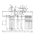
- FIG. 1 shows a schematic side view of a plate filter press.
- the plate filter press comprises a detachable pressure piece 1 and a large number of filter plates, the first four of which are numbered 2, 3, 4 and 5.
- the filters plates are connected to one another via chains 6 or other spacer elements, so that when one of the filter plates comes to rest on the open pressure piece 1 or on the filter plates already located there, the next filter plate, in this case filter plate 3, has reached its cleaning position and the next two filter plates 4 and 5 have been pulled from the plate stack.
- a cleaning carriage 7 can be moved in the direction of movement of the filter plates.
- the cleaning trolley 7 carries a cleaning device 8 in the form of a spray tube, which can be moved up and down by a motor 9 via a chain.
- the cleaning carriage 7 carries a piston-cylinder unit 10, which forms a drive and a filter plate driver.
- the piston-cylinder unit is pivotally attached to one arm 13 of a two-armed lever 13, 14, which in turn is articulated via a bracket 15 on the cleaning trolley.
- the other arm 14 carries a brake shoe 11, which rests against a brake drum 16 under the action of a compression spring 12.
- the piston-cylinder unit 10 has just brought the cleaning trolley 7 into its cleaning position above the space between the filter plates 2 and 3.
- the cleaning carriage 7 is held here by the brake 11, 16.
- the piston rod of the piston-cylinder unit 10 can now be drawn in, overflowing the filter plate 3 and engaging with it.
- the piston rod is pushed out again, bringing the filter plate 3 into contact with the filter plate 2. Subsequently the extension stroke of the piston rod continues. It overcomes the force of the compression spring 12. The brake is therefore released and the cleaning carriage 7 moves away from the pressure piece 1 by a filter plate width. It reaches its next cleaning position with regard to the space between the filter plates 3 and 4, in which it is stopped by switching off the piston-cylinder unit by means of a contactless limit switch 17. The brake 11, 16 engages again, and the work cycle described can begin again.
- the brake 11, 16 is released manually, for example, the piston-cylinder unit 10 is raised by means of a lever pull 18 and the cleaning carriage 7 is pushed into its corresponding position near the pressure piece 1.
- the further work process proceeds automatically after the piston-cylinder unit has been lowered. When all the plates have been cleaned, the carriage is pushed into the starting position by hand.
Landscapes
- Chemical & Material Sciences (AREA)
- Chemical Kinetics & Catalysis (AREA)
- Filtration Of Liquid (AREA)
Applications Claiming Priority (2)
| Application Number | Priority Date | Filing Date | Title |
|---|---|---|---|
| DE3043821A DE3043821C2 (de) | 1980-11-20 | 1980-11-20 | Plattenfilterpresse mit einem Reinigungswagen |
| DE3043821 | 1980-11-20 |
Publications (3)
| Publication Number | Publication Date |
|---|---|
| EP0052810A2 true EP0052810A2 (fr) | 1982-06-02 |
| EP0052810A3 EP0052810A3 (en) | 1982-07-14 |
| EP0052810B1 EP0052810B1 (fr) | 1983-11-30 |
Family
ID=6117223
Family Applications (1)
| Application Number | Title | Priority Date | Filing Date |
|---|---|---|---|
| EP81109382A Expired EP0052810B1 (fr) | 1980-11-20 | 1981-10-30 | Filtre presse à plateaux pourvue d'un chariot de nettoyage |
Country Status (4)
| Country | Link |
|---|---|
| US (1) | US4405457A (fr) |
| EP (1) | EP0052810B1 (fr) |
| CA (1) | CA1176992A (fr) |
| DE (2) | DE3043821C2 (fr) |
Cited By (5)
| Publication number | Priority date | Publication date | Assignee | Title |
|---|---|---|---|---|
| DE3742363C1 (en) * | 1987-12-14 | 1988-11-17 | Netzsch Maschinenfabrik | Shunting appliance for filter plates |
| FR2631559A1 (fr) * | 1988-05-21 | 1989-11-24 | Putsch & Co H | Dispositif pour le transport et le verrouillage des plateaux de filtre-presses |
| EP0702992A1 (fr) * | 1994-09-22 | 1996-03-27 | Sala International AB | Procédé et dispositif relatif à des press-filters |
| CN106984076A (zh) * | 2017-05-22 | 2017-07-28 | 苏子战 | 一种压滤机用滤板间距调节链结 |
| CN107050946A (zh) * | 2017-05-17 | 2017-08-18 | 苏子战 | 一种可调节间距和厚度的板框式滤板 |
Families Citing this family (12)
| Publication number | Priority date | Publication date | Assignee | Title |
|---|---|---|---|---|
| DE3833391A1 (de) * | 1987-11-28 | 1989-06-08 | Kloeckner Humboldt Deutz Ag | Vorrichtung zum auspressen von fluessigkeit aus schuett- und/oder rieselfaehigem gut |
| AU600866B2 (en) * | 1987-12-26 | 1990-08-23 | Ishigaki Kiko Co. Ltd. | Apparatus for cake removal in a filter press |
| US5370795A (en) * | 1992-06-25 | 1994-12-06 | Jwi, Inc. | Plate shifter for filter press |
| US5328617A (en) * | 1992-09-28 | 1994-07-12 | Jwi, Inc. | Air-assist discharge of filter press cake |
| DE19733486C1 (de) * | 1997-08-01 | 1998-09-24 | Netzsch Erich Holding | Antrieb für Reinigungs- und Verschiebevorrichtungen an Filterpressen |
| US5855778A (en) * | 1997-08-07 | 1999-01-05 | William R. Perrin Ontario Ltd. | Filter press |
| US7229264B2 (en) * | 2004-07-28 | 2007-06-12 | Wayne Crooks | Platen with self-cleaning exhaust holes and multi-opening press utilizing same |
| RU2312699C1 (ru) * | 2006-03-31 | 2007-12-20 | Общество с ограниченной ответственностью "Научно-производственная компания - Восточная Украина" | Фильтр-пресс с промывным устройством |
| US9237822B2 (en) * | 2009-09-23 | 2016-01-19 | Theresa Peronti | Hand operated fruit squeezer |
| CN106310753B (zh) * | 2016-10-27 | 2019-10-25 | 康明克斯(北京)机电设备有限公司 | 一种采用卧式油缸的新型压滤机 |
| CN110420485A (zh) * | 2019-05-14 | 2019-11-08 | 景津环保股份有限公司 | 一种滤板分三组开闭压滤机 |
| SE545705C2 (en) * | 2022-03-24 | 2023-12-12 | Luossavaara Kiirunavaara Ab | A pendulum supporting device and a filter press apparatus comprising the device |
Family Cites Families (9)
| Publication number | Priority date | Publication date | Assignee | Title |
|---|---|---|---|---|
| DE1302541B (fr) * | 1961-03-25 | 1972-05-31 | ||
| FR1464767A (fr) * | 1965-11-22 | 1967-01-06 | Sarl A Faure & Cie | Filtre-presse à débâtissage automatisé |
| US3637082A (en) * | 1969-06-20 | 1972-01-25 | Shriver & Co Inc T | Plate shifter and scraper assembly for filter presses |
| DE2627579C2 (de) * | 1976-06-19 | 1985-01-10 | Rittershaus & Blecher Gmbh, 5600 Wuppertal | Filterpresse |
| JPS5419268A (en) * | 1977-07-14 | 1979-02-13 | Ngk Insulators Ltd | Device of partially opening filter plate of filter press |
| DE2741659A1 (de) * | 1977-09-16 | 1979-03-22 | Wilms Gmbh | Filteranlage |
| NL7803430A (nl) * | 1978-03-31 | 1979-10-02 | Holland Bergen Machine | Filterpers. |
| DE2847734A1 (de) * | 1978-11-03 | 1980-05-14 | Wilms Gmbh | Filterpresse |
| DE2914448C2 (de) * | 1979-04-10 | 1984-06-28 | Eberhard Hoesch & Söhne GmbH & Co, 5160 Düren | Vorrichtung zum Verschieben der Filterplatten einer Filterpresse |
-
1980
- 1980-11-20 DE DE3043821A patent/DE3043821C2/de not_active Expired
-
1981
- 1981-10-30 DE DE8181109382T patent/DE3161561D1/de not_active Expired
- 1981-10-30 EP EP81109382A patent/EP0052810B1/fr not_active Expired
- 1981-11-09 US US06/319,141 patent/US4405457A/en not_active Expired - Fee Related
- 1981-11-18 CA CA000390389A patent/CA1176992A/fr not_active Expired
Cited By (7)
| Publication number | Priority date | Publication date | Assignee | Title |
|---|---|---|---|---|
| DE3742363C1 (en) * | 1987-12-14 | 1988-11-17 | Netzsch Maschinenfabrik | Shunting appliance for filter plates |
| FR2631559A1 (fr) * | 1988-05-21 | 1989-11-24 | Putsch & Co H | Dispositif pour le transport et le verrouillage des plateaux de filtre-presses |
| EP0702992A1 (fr) * | 1994-09-22 | 1996-03-27 | Sala International AB | Procédé et dispositif relatif à des press-filters |
| AU684379B2 (en) * | 1994-09-22 | 1997-12-11 | Svedala Pumps & Process Aktiebolag | A method and arrangement relating to press filters |
| US5728307A (en) * | 1994-09-22 | 1998-03-17 | Sala International Ab | Method of emptying the press chambers of a press filter and an apparatus therefor |
| CN107050946A (zh) * | 2017-05-17 | 2017-08-18 | 苏子战 | 一种可调节间距和厚度的板框式滤板 |
| CN106984076A (zh) * | 2017-05-22 | 2017-07-28 | 苏子战 | 一种压滤机用滤板间距调节链结 |
Also Published As
| Publication number | Publication date |
|---|---|
| US4405457A (en) | 1983-09-20 |
| EP0052810B1 (fr) | 1983-11-30 |
| DE3043821A1 (de) | 1982-07-08 |
| DE3161561D1 (en) | 1984-01-05 |
| DE3043821C2 (de) | 1983-10-20 |
| CA1176992A (fr) | 1984-10-30 |
| EP0052810A3 (en) | 1982-07-14 |
Similar Documents
| Publication | Publication Date | Title |
|---|---|---|
| EP0052810B1 (fr) | Filtre presse à plateaux pourvue d'un chariot de nettoyage | |
| EP0532136B1 (fr) | Séparateur magnétique à chaînes | |
| DE69019791T2 (de) | Vorrichtung zum Abtrennen von geformten Gummigegenständen aus einer geformten Folie. | |
| DE2224592C3 (de) | Doppelt wirkende hydraulische Pulverpresse mit einem einzigen Hydraulikzylinder | |
| DE2823501A1 (de) | Plattenfilterpresse mit steuereinrichtung fuer die bewegung der plattenverschiebevorrichtung und etwaiger integrierter zusatzeinrichtungen | |
| DE2001193B2 (de) | Filterpresse | |
| AT5768U2 (de) | Stopfmaschine | |
| DE3123396A1 (de) | Vorrichtung zum reinigen eines pressstempels in einer presse, insbesondere steinpresse | |
| DE1940426C3 (de) | Steuervorrichtung fur eine Band haspelanlage | |
| DE3240962C2 (de) | Palettenwechselvorrichtung | |
| DE69104339T2 (de) | Vorrichtung zum Entsanden von Gusstücken. | |
| DE1752366B2 (de) | Verdichtungspresse | |
| DE9319221U1 (de) | Vorrichtung zum Reinigen, insbesondere von Kohlestaubfiltern | |
| DE2544581A1 (de) | Plattenfilterpresse | |
| DE2849145C3 (de) | Spritzgießform für Transportkästen, bei der Formbachken auf schrägen Führrungssäulen verschiebbar sind | |
| DE3529775A1 (de) | Vorrichtung zur herstellung von formteilen | |
| DE3831361C2 (de) | Vorrichtung zum Ausbringen eines Formteils von hydraulischen Pressen | |
| DE3050260C2 (de) | Automatische Sandslingerformmaschine | |
| DE29821379U1 (de) | Formschließanordnung einer Spritzgußformmaschine | |
| DE102018118131B3 (de) | Reinigungsvorrichtung und Verfahren zum Reinigen eines Innengewindes einer Deckelverschraubung eines Reaktordruckbehälters | |
| DE3640762C2 (fr) | ||
| DE2631789C3 (de) | Fördervorrichtung für aus einer Spritzgießform ausgeworfene Spritzgu fiteile | |
| DE2801436A1 (de) | Vorrichtung zum trennen von pressplatten, insbesondere in filterpressen | |
| DE19618550A1 (de) | Filterpresse | |
| DE1602638C (de) | Vorrichtung zum Herstellen von ringförmigen Federn aus geraden, an einem Ende konisch verjüngten Schraubenfedern |
Legal Events
| Date | Code | Title | Description |
|---|---|---|---|
| PUAI | Public reference made under article 153(3) epc to a published international application that has entered the european phase |
Free format text: ORIGINAL CODE: 0009012 |
|
| PUAL | Search report despatched |
Free format text: ORIGINAL CODE: 0009013 |
|
| AK | Designated contracting states |
Designated state(s): CH DE FR GB IT LI |
|
| AK | Designated contracting states |
Designated state(s): CH DE FR GB IT LI |
|
| 17P | Request for examination filed |
Effective date: 19820816 |
|
| ITF | It: translation for a ep patent filed | ||
| GRAA | (expected) grant |
Free format text: ORIGINAL CODE: 0009210 |
|
| AK | Designated contracting states |
Designated state(s): CH DE FR GB IT LI |
|
| REF | Corresponds to: |
Ref document number: 3161561 Country of ref document: DE Date of ref document: 19840105 |
|
| ET | Fr: translation filed | ||
| PLBE | No opposition filed within time limit |
Free format text: ORIGINAL CODE: 0009261 |
|
| STAA | Information on the status of an ep patent application or granted ep patent |
Free format text: STATUS: NO OPPOSITION FILED WITHIN TIME LIMIT |
|
| PGFP | Annual fee paid to national office [announced via postgrant information from national office to epo] |
Ref country code: FR Payment date: 19841016 Year of fee payment: 4 |
|
| PGFP | Annual fee paid to national office [announced via postgrant information from national office to epo] |
Ref country code: CH Payment date: 19841122 Year of fee payment: 4 |
|
| 26N | No opposition filed | ||
| PGFP | Annual fee paid to national office [announced via postgrant information from national office to epo] |
Ref country code: DE Payment date: 19841220 Year of fee payment: 4 |
|
| PG25 | Lapsed in a contracting state [announced via postgrant information from national office to epo] |
Ref country code: LI Effective date: 19851031 Ref country code: CH Effective date: 19851031 |
|
| REG | Reference to a national code |
Ref country code: CH Ref legal event code: PL |
|
| PG25 | Lapsed in a contracting state [announced via postgrant information from national office to epo] |
Ref country code: FR Free format text: LAPSE BECAUSE OF NON-PAYMENT OF DUE FEES Effective date: 19870630 |
|
| GBPC | Gb: european patent ceased through non-payment of renewal fee | ||
| REG | Reference to a national code |
Ref country code: FR Ref legal event code: ST |
|
| PG25 | Lapsed in a contracting state [announced via postgrant information from national office to epo] |
Ref country code: GB Effective date: 19881118 |
|
| PG25 | Lapsed in a contracting state [announced via postgrant information from national office to epo] |
Ref country code: DE Effective date: 19890701 |