EP0052859A1 - Selbsttätig schaltbarer Ventilator für Kühlsysteme von Verbrennungsmotoren - Google Patents
Selbsttätig schaltbarer Ventilator für Kühlsysteme von Verbrennungsmotoren Download PDFInfo
- Publication number
- EP0052859A1 EP0052859A1 EP81109753A EP81109753A EP0052859A1 EP 0052859 A1 EP0052859 A1 EP 0052859A1 EP 81109753 A EP81109753 A EP 81109753A EP 81109753 A EP81109753 A EP 81109753A EP 0052859 A1 EP0052859 A1 EP 0052859A1
- Authority
- EP
- European Patent Office
- Prior art keywords
- bellows
- tight
- gas
- fan
- front plate
- Prior art date
- Legal status (The legal status is an assumption and is not a legal conclusion. Google has not performed a legal analysis and makes no representation as to the accuracy of the status listed.)
- Granted
Links
- 238000001816 cooling Methods 0.000 title claims abstract description 24
- 238000002485 combustion reaction Methods 0.000 title claims description 6
- 239000011888 foil Substances 0.000 claims description 12
- 239000002184 metal Substances 0.000 claims description 11
- 230000001681 protective effect Effects 0.000 claims description 8
- 230000008878 coupling Effects 0.000 claims description 7
- 238000010168 coupling process Methods 0.000 claims description 7
- 238000005859 coupling reaction Methods 0.000 claims description 7
- 230000005540 biological transmission Effects 0.000 abstract description 3
- 239000012530 fluid Substances 0.000 abstract 2
- 239000010408 film Substances 0.000 description 8
- 239000007788 liquid Substances 0.000 description 7
- XLYOFNOQVPJJNP-UHFFFAOYSA-N water Substances O XLYOFNOQVPJJNP-UHFFFAOYSA-N 0.000 description 6
- 238000005476 soldering Methods 0.000 description 5
- 238000003466 welding Methods 0.000 description 5
- 238000009835 boiling Methods 0.000 description 4
- 238000010276 construction Methods 0.000 description 3
- 239000012528 membrane Substances 0.000 description 3
- 238000006073 displacement reaction Methods 0.000 description 2
- 239000011810 insulating material Substances 0.000 description 2
- 238000009413 insulation Methods 0.000 description 2
- 238000004519 manufacturing process Methods 0.000 description 2
- 239000000463 material Substances 0.000 description 2
- 125000006850 spacer group Chemical group 0.000 description 2
- 230000003068 static effect Effects 0.000 description 2
- BOSAWIQFTJIYIS-UHFFFAOYSA-N 1,1,1-trichloro-2,2,2-trifluoroethane Chemical compound FC(F)(F)C(Cl)(Cl)Cl BOSAWIQFTJIYIS-UHFFFAOYSA-N 0.000 description 1
- AJDIZQLSFPQPEY-UHFFFAOYSA-N 1,1,2-Trichlorotrifluoroethane Chemical compound FC(F)(Cl)C(F)(Cl)Cl AJDIZQLSFPQPEY-UHFFFAOYSA-N 0.000 description 1
- 230000015572 biosynthetic process Effects 0.000 description 1
- 238000005266 casting Methods 0.000 description 1
- 239000013013 elastic material Substances 0.000 description 1
- 239000000945 filler Substances 0.000 description 1
- 230000017525 heat dissipation Effects 0.000 description 1
- 239000002655 kraft paper Substances 0.000 description 1
- 230000007774 longterm Effects 0.000 description 1
- 239000007769 metal material Substances 0.000 description 1
- 238000003825 pressing Methods 0.000 description 1
- 230000002265 prevention Effects 0.000 description 1
- 238000007789 sealing Methods 0.000 description 1
- 238000003860 storage Methods 0.000 description 1
- 239000000126 substance Substances 0.000 description 1
- 239000000725 suspension Substances 0.000 description 1
- 239000010409 thin film Substances 0.000 description 1
Images




Classifications
-
- F—MECHANICAL ENGINEERING; LIGHTING; HEATING; WEAPONS; BLASTING
- F01—MACHINES OR ENGINES IN GENERAL; ENGINE PLANTS IN GENERAL; STEAM ENGINES
- F01P—COOLING OF MACHINES OR ENGINES IN GENERAL; COOLING OF INTERNAL-COMBUSTION ENGINES
- F01P7/00—Controlling of coolant flow
- F01P7/02—Controlling of coolant flow the coolant being cooling-air
- F01P7/08—Controlling of coolant flow the coolant being cooling-air by cutting in or out of pumps
- F01P7/081—Controlling of coolant flow the coolant being cooling-air by cutting in or out of pumps using clutches, e.g. electro-magnetic or induction clutches
- F01P7/082—Controlling of coolant flow the coolant being cooling-air by cutting in or out of pumps using clutches, e.g. electro-magnetic or induction clutches using friction clutches
- F01P7/085—Controlling of coolant flow the coolant being cooling-air by cutting in or out of pumps using clutches, e.g. electro-magnetic or induction clutches using friction clutches actuated by fluid pressure
-
- F—MECHANICAL ENGINEERING; LIGHTING; HEATING; WEAPONS; BLASTING
- F01—MACHINES OR ENGINES IN GENERAL; ENGINE PLANTS IN GENERAL; STEAM ENGINES
- F01P—COOLING OF MACHINES OR ENGINES IN GENERAL; COOLING OF INTERNAL-COMBUSTION ENGINES
- F01P7/00—Controlling of coolant flow
- F01P7/02—Controlling of coolant flow the coolant being cooling-air
- F01P7/08—Controlling of coolant flow the coolant being cooling-air by cutting in or out of pumps
- F01P7/081—Controlling of coolant flow the coolant being cooling-air by cutting in or out of pumps using clutches, e.g. electro-magnetic or induction clutches
- F01P7/082—Controlling of coolant flow the coolant being cooling-air by cutting in or out of pumps using clutches, e.g. electro-magnetic or induction clutches using friction clutches
- F01P7/087—Controlling of coolant flow the coolant being cooling-air by cutting in or out of pumps using clutches, e.g. electro-magnetic or induction clutches using friction clutches actuated directly by deformation of a thermostatic device
-
- F—MECHANICAL ENGINEERING; LIGHTING; HEATING; WEAPONS; BLASTING
- F01—MACHINES OR ENGINES IN GENERAL; ENGINE PLANTS IN GENERAL; STEAM ENGINES
- F01P—COOLING OF MACHINES OR ENGINES IN GENERAL; COOLING OF INTERNAL-COMBUSTION ENGINES
- F01P7/00—Controlling of coolant flow
- F01P7/02—Controlling of coolant flow the coolant being cooling-air
- F01P7/08—Controlling of coolant flow the coolant being cooling-air by cutting in or out of pumps
- F01P7/081—Controlling of coolant flow the coolant being cooling-air by cutting in or out of pumps using clutches, e.g. electro-magnetic or induction clutches
- F01P7/082—Controlling of coolant flow the coolant being cooling-air by cutting in or out of pumps using clutches, e.g. electro-magnetic or induction clutches using friction clutches
- F01P7/088—Controlling of coolant flow the coolant being cooling-air by cutting in or out of pumps using clutches, e.g. electro-magnetic or induction clutches using friction clutches actuated in response to driving speed, e.g. by centrifugal devices
-
- F—MECHANICAL ENGINEERING; LIGHTING; HEATING; WEAPONS; BLASTING
- F16—ENGINEERING ELEMENTS AND UNITS; GENERAL MEASURES FOR PRODUCING AND MAINTAINING EFFECTIVE FUNCTIONING OF MACHINES OR INSTALLATIONS; THERMAL INSULATION IN GENERAL
- F16D—COUPLINGS FOR TRANSMITTING ROTATION; CLUTCHES; BRAKES
- F16D43/00—Automatic clutches
- F16D43/02—Automatic clutches actuated entirely mechanically
- F16D43/25—Automatic clutches actuated entirely mechanically controlled by thermo-responsive elements
Definitions
- the invention relates to an automatically switchable fan, in particular for cooling systems of internal combustion engines, with an annular thermostat swept by the cooling air, which is designed as a gas-tight container with a fixed front plate facing the cooling air flow and a radially flexible wall and contains a medium which is at a predetermined temperature increase acts on the flexible wall in the sense of a coupling of the fan to a drive shaft of the internal combustion engine.
- the thermostat In the known embodiment of the thermostat, it consists of a metal disc arranged on the end face and exposed to the cooling air flow and a membrane made of rubber-elastic material.
- the metal disc is profiled so that there is a cavity between it and the membrane, which is gas-tight to the outside. The operation of this thermostat is described in DE-PS 26 35 896 in detail.
- the present invention is based on the object of improving the fan of the type mentioned in such a way that the disadvantages shown no longer have to be accepted, given the economy of its production.
- the container comprises a bellows or parts of the same, which are connected in a rotationally fixed and gas-tight manner to the fixed front plate swept by the cooling air flow, and in that one or more elements are provided which are connected to the front plate in a heat-conducting manner in the Reach the cavity of the container and determine a selectable minimum distance between the front plate and the flexible wall of the container.
- the one or more heat-conducting elements which are thermally conductively connected to the fixed front plate serve to improve the heat-conducting connection between the front plate of the thermostat facing the cooling air flow and the filling medium located in the bellows. Since they protrude into the cavity formed by the bellows, they accelerate the heat exchange with the filling medium.
- these elements determine a selectable minimum distance between the front plate and the flexible wall of the container.
- a bellows or the parts thereof are made of metal, is particularly well suited for creating a cavity with excellent gas tightness. Its edge areas can be connected, for example, by gas soldering or welding to the fixed front plate facing the cooling air flow, both gastight and with excellent thermal conductivity. But also clamp connections of the edge area of the bellows with the inner hub of the fan have proven to be gas-tight. Such clamp connections can be additionally protected against heat loss by using brackets made of insulating material.
- the bellows is preferably formed from one or more foils, at least one of which has a gas-tight structure and, if appropriate, is combined with further foils arranged in layers, which are in turn provided with slits or openings.
- At least one of the foils with slits or openings can also be designed as a protective foil for the gas-tight foil in order to protect it along its outer surfaces against overpressures prevailing in the interior of the bellows.
- the bellows can preferably be designed as a bellows with one or more shafts.
- the gas-tight films are in the form of annular shells, either two of these shells being combined along their edges to form a gas-tight cavity which is thermally conductively connected to the front plate or a ring-shaped shell is directly connected to the front plate in a heat-conducting manner along its edges.
- the gas-tight shells forming the bellows are preferably combined in the interior of the bellows with correspondingly shaped shells made of the rigid support film provided with slots or openings and, if appropriate, on the outer surface of the bellows with correspondingly shaped shells made of the elastic protective film provided with slots or openings, so that they together form a multi-layer bellows.
- a housing 1 of a water pump is connected to a motor in a known manner.
- the water pump shaft 2 is mounted in the housing 1 by means of ball bearings 3.
- a pump impeller 4 is pressed onto the water pump shaft 2.
- a shaft seal 5 separates the water space from the bearing part.
- a hub 6 is also pressed onto the water pump shaft 2, on which a V-belt pulley consisting of parts 7 and 8 and a counter pulley 9 belonging to the coupling are fastened by means of rivets 10.
- a fan is freely rotatably mounted on an attached part 11 of the pump shaft 2. This storage can be carried out in various ways, for example, a slide bearing or a Needle bearing possible.
- the fan consists of the inner hub part 18, which is mounted here on the part 11 of the pump shaft 2 via the ball bearings 12 and 13, and an annular outer hub part 19, which carries blades 20 and 21.
- the number and design of the wings is generally known in practice.
- the hub part 19 with the wings is preferably made of plastic.
- the two ball bearings 12 and 13 are selected in the present example for better thermal insulation compared to part 11 of the pump shaft 2.
- a snap ring 14, a spacer ring 15 and an annular flange 16 of an inner hub part 18 of the fan form a clamping connection in order to secure the fan against axial displacement.
- the hub parts 18 and 19 of the fan are connected to a thermostat.
- the thermostat consists of a metallic front plate 22, a bellows 23 made of metal and a base plate 24, which is fixedly arranged on the end face and exposed to the cooling air flow.
- the bellows 23 creates a cavity between the front plate 22 and the base plate 24 into which the filling medium can be filled .
- the Faltenbalo23 is formed with an inner and an outer bellows part 23 a, b. These two parts 23 a, b are connected gas-tight by means of the likewise metallic base plate 24 by welding or soldering.
- the metallic front plate 22 is connected to the bellows ends 32 and 33 (FIG. 3) in a gas-tight manner, preferably by soldering or welding. With the inner B algend 32, however, it is already sufficient if, as shown, it is connected to the inner hub part 18 in a rotationally fixed and gas-tight manner together with the front plate 22 only by means of a clamp connection.
- the first ring 1 consists of a ring 26, a spring ring 27 (see also FIGS. 4 and 5) and a ring 28.
- the front plate 22 and the inner bellows edge 32 are together with the three rings 26, 27 and 28 mentioned clamped between an extension 25 of the inner hub part 18 and a snap ring 29.
- the thermostat 22, 23, 24 in the clamping device 25, 26, 27, 28, 29 is held in a pair of rings 37 made of insulating material.
- the described clamping device can also be replaced by a suitable screw connection.
- the ring 34 In addition to its task of conducting the heat from the front plate 22 well and quickly into the interior of the bellows 23, the ring 34 also has the task of preventing the bellows from being compressed inadmissibly. Its extension in the axial direction is therefore chosen in accordance with the minimum permissible distance between the front plate 23 and base plate 24. So that the filling medium can communicate in front of and behind the spaces of the ring 34, the ring has notches 35 arranged distributed along its circumference.
- individual segments can also be arranged in a ring on the front plate 22.
- Other shapes, such as radial ribs (not shown) are also conceivable.
- the front plate 22 On its surface exposed to the cooling air flow, the front plate 22 carries cooling fins 36, which are also connected to the front plate 22 in a highly heat-conducting manner.
- the front plate 22 can be produced, for example together with the elements 34 and 36, in a pressing or casting process.
- a friction lining 31 made of a material suitable for friction clutches is fastened on the disk 9 belonging to the clutch. This friction lining could also be attached to the base plate 24 of the thermostat, but this is not shown in a drawing.
- a plate spring 3 0th Between a radially outwardly projecting ring flange of the ring 28 and the base plate 24 is a plate spring 3 0th With this, the pressure acting on the filling medium of the thermostat can be influenced and also the self-suspension of the bellows can be taken into account.
- Trichlorotrifluoroethane (C 2 C1 3 F 3 ), which is known under the trade name "Frigen 113”, can be used as the filling medium, for example.
- the filling medium can also consist of two or more different liquids, but the boiling point of none of the substances should be significantly below the desired switch-on temperature of the thermostat.
- a metal bellows is used in the embodiment of the fan according to the invention shown in FIG. 6 ′, which can be referred to as a bellows with a single shaft.
- the metal bellows shown in FIG. 6 is formed from two annular shells 38 and 39, the edges of which are connected in a gastight manner by soldering or welding in order to create an annular cavity 4o which concentrically surrounds the inner hub 18 of the fan.
- a ring 41 is provided here as a good heat-conducting element, which is connected to the front plate 42 in a highly heat-conductive manner, preferably also by soldering or welding.
- Grooves 43 are embedded on the circumference of the ring 41 in order to enable free circulation of the filling medium in the cavity 4o.
- the fixed wall of the shell 38 is also connected to the front plate 42.
- a pressure plate 44 abutting against the resilient wall of the shell 49, the surface of which lying away from the shell is provided with a friction lining 45, is pressed onto a counter disc 46 seated on the motor shaft 2 and so that the fan is coupled in the frictional connection.
- the pressure plate 44 is axially displaceable on the inner fan hub 47 and is positively connected to it by means of teeth and grooves.
- the front plate 42 which is also fastened to the inner fan hub 47 and is connected to the outer hub 48 which carries the fan blades, causes the pressure plate 44 and the counter disc 46, the rotation of the fan blades.
- the thermostat is formed by a bellows designed as an annular shell 61, the edges of which are directly soldered or welded to the front plate 50 in a gastight manner.
- the shell 61 in the exemplary embodiment comprises a very thin gas-tight metal foil (FIG. 8).
- This metal foil 51 is shell-shaped. However, it is extremely sensitive to changes in pressure and must therefore be protected against overstress by supporting or protective shells.
- a suitable rigid rigid support shell 52 is shown, the shape of which essentially corresponds to that of the shell 51. However, their surface is provided with slots 59 to a to allow good circulation of the filling medium in the shell or bellows interior.
- the support shell 52 is also made of metal and at the same time fulfills the task of good heat transfer from the front plate 50 to the filling medium. It also serves. it as a spacer between the front plate 5o and the shell 51 to ensure a selectable minimum distance between the ring surface of the shell 51 and the front plate 5o.
- the slots 59 of the shell 52 run in the radial direction and have the further task of reducing the rigidity of the support shell 52. Instead of the slots 59, however, openings of any shape and in any number and arrangement can also be selected.
- a further annular shell 53 which is arranged as a protective shell on the outer surface of the shell 51, serves to overstress - Prevention of the shell 51 by increased internal pressure.
- the shell 53 is also with radial slots 6 0 or other arbitrarily arranged openings. provided, but in contrast to the support shell 52 it can also consist of a plastic material, so that the lifting movement of the shell 51 required for the coupling when the filling medium is increased in pressure is not impeded.
- the rigid support shell 52 has to resist the spring 54.
- the described, essentially mutually identical shells 53, 51 and 52 are in the mentioned order pushed over each other and united at their edges with the front panel 5b. At least the shells 51 and 52 formed from metal are soldered or welded gas-tight to the front plate 50 along their edge zones.
- one or more shells 51 can also be made of plastic, provided that at least one shell 51 ensures a gas-tight connection to the front panel, which can preferably be achieved by choosing a metallic foil.
- the shell 53 since it has no sealing function, can also be made of plastic in order to achieve good elasticity. Only the plate 52, which in addition to its supporting function also has the task of good heat transfer from the front plate to the filling medium, should be made of a metallic material.
- a pressure plate 55 is also provided in the embodiment shown in FIG. 7, which is connected to the outer hub part 56 of the fan is positively connected by means of teeth 57 and grooves 58.
- the mode of operation of the fan described in connection with FIG. 1 essentially corresponds to that of the training forms shown in FIGS. 6 and 7, so that these no longer have to be discussed in detail.
Landscapes
- Engineering & Computer Science (AREA)
- General Engineering & Computer Science (AREA)
- Mechanical Engineering (AREA)
- Chemical & Material Sciences (AREA)
- Combustion & Propulsion (AREA)
- Physics & Mathematics (AREA)
- Fluid Mechanics (AREA)
- Structures Of Non-Positive Displacement Pumps (AREA)
- Control Of Positive-Displacement Air Blowers (AREA)
- Details Of Measuring And Other Instruments (AREA)
- General Details Of Gearings (AREA)
- Control Of Temperature (AREA)
Abstract
Description
- Die Erfindung betrifft einen selbsttätig schaltbaren Ventilator, insbesondere für Kühlsysteme von Verbrennungsmotoren, mit einem von der Kühlluft überstrichenen, ringförmigen Thermostaten, der als gasdichter Behälter mit einer festen, dem Kühlluftstrom zugewandten Frontplatte und einer radial nachgiebigen Wandung ausgebildet ist und ein Medium enthält, das bei einer vorgegebenen Temperaturerhöhung auf die nachgiebige Wandung im Sinne einer Ankupplung des Ventilators an eine Antriebswelle des Verbrennungsmotors einwirkt.
- Bei der bekannten Ausführungsform des Thermostaten besteht dieser aus einer stirnseitig angeordneten, dem Kühlluftstrom ausgesetzten Metallscheibe und einer Membran aus gummielastischem Material. Die Metallscheibe ist so profiliert, daß zwischen ihr und der Membran ein Hohlraum besteht, der gegenüber dem Außenraum gasdicht ausgeführt ist. Die Wirkungsweise dieses Thermostaten ist in der DE-PS 26 35 896 im einzelnen beschrieben.
- Es hat sich nun gezeigt, daß die bekannte Konstruktion des Thermostaten auf lange Sicht gesehen keine zufriedenstellende Gasdichtheit aufweist und die gasdichte Einspannung von Kunststoffmembranen große Schwierigkeiten bereitet.
- Ferner ist bei der bekannten Konstruktion auch das Problem der Wärmeübertragung vom Außenraum auf das Füllmedium noch nicht optimal gelöst, da die Befestigungen der genannten Bestandteile des Thermostaten eine beachtliche Wärmeableitung und damit einen großen Wärmeverlust bedingen.
- Der vorliegenden Erfindung liegt nun die Aufgabe zugrunde, den Ventilator der genannten Art derart zu verbessern, daß bei Wirtschaftlichkeit seiner Herstellung die aufgezeigten Nachteile nicht mehr in Kauf genommen werden müssen.
- Erfindungsgemäß wird dies dadurch erreicht, daß der Behälter einen Balg oder Teile desselben umfaßt, die mit der festen, vom Kühlluftstrom überstrichenen Frontplatte drehfest und gasdicht verbunden sind und daß ferner ein oder mehrere Elemente vorgesehen sind, die mit der Frontplatte wärmeleitend verbunden sind, in den Hohlraum des Behälters hineinreichen und einen wählbaren Mindestabstand zwischen der Frontplatte und der nachgiebigen Wandung des Behälters bestimmen.
- Die mit der festen Frontplatte wärmeleitend verbundenen, ein oder mehreren wärmeleitenden Elemente dienen zur Verbesserung der wärmeleitenden Verbindung zwischen der dem Kühlluftstrom zugewandten Frontplatte des Thermostaten und dem im Balg befindlichen Füllmedium. Da sie in den durch den Balg gebildeten Hohlraum hineinragen, beschleunigen sie den Wärmeaustausch mit dem Füllmedium.
- Gleichzeitig bestimmen diese Elemente einen wählbaren Mindestabstand zwischen der Frontplatte und der nachgiebigen Wandung des Behälters.
- Es hat sich gezeigt, daß ein Balg der oder dessen Teile aus Metall bestehen, für die Schaffung eines Hohlraumes mit ausgezeichneter Gasdichtheit besonders gut geeignet ist. Seine Randbereiche lassen sich beispielsweise durch Verlöten oder Verschweißen mit der festen, dem Kühlluftstrom zugewandten Frontplatte sowohl gasdicht, als auch mit hervorragender Wärmeleitfähigkeit verbinden. Aber auch Klemmverbindungen des Randbereiches des Balges mit der Innennabe des Ventilators haben sich als gasdicht erwiesen. Solche Klemmverbindungen können durch Verwendung von Halterungen aus isolierendem Material gegen Wärmeverluste noch zusätzlich geschützt sein..
- Vorzugsweise ist der Balg aus einer oder mehreren Folien gebildet, von denen mindestens eine eine gasdichte Struktur aufweist und ggf. mit weiteren, schichtartig zu dieser angeordneten Folien kombiniert ist, die ihrerseits mit Schlitzen oder Durchbrüchen versehen sind. Insbesondere ist es von Vorteil, mindestens eine der Folien mit Schlitzen oder Durchbrüchen als Stützfolie für die gasdichte Folie auszubilden und längs deren Oberfläche im Innenraum des Balges anzuordnen. Mindestens eine der Folien mit Schlitzen oder Durchbrüchen kann ferner als Schutzfolie für die gasdichte Folie ausgebildet sein, um diese längs deren Außenflächen gegen im Innenraum des Balg herrschende Überdrucke zu schützen. Man kann den Balg vorzugsweise als Faltenbalg mit einer oder mehreren Wellen ausbilden.
- Bei einer wegen ihrer wirtschaftlichen Herstellung besonders interessanten und bevorzugten Ausbildung des Behälters für das Füllmedium, liegen die gasdichten Folien in Form ringförmiger Schalen vor, wobei entweder zwei dieser Schalen längs ihrer Ränder zu einem gasdichten Hohlraum vereinigt sind, der mit der Frontplatte wärmeleitend verbunden ist oder eine ringförmige Schale ist längs ihrer Ränder unmittelbar mit der Frontplatte wärmeleitend verbunden. Dabei sind vorzugsweise die den Balg bildenden gasdichten Schalen im Balginnenraum mit entsprechend geformten Schalen aus der mit Schlitzen oder Durchbrüchen versehenen biegesteifen Stützfolie und ggf. auf der Außenfläche des Balgs mit entsprechend geformten Schalen aus der mit Schlitzen oder Durchbrüchen versehenen elastischen Schutzfolie kombiniert, so daß sie gemeinsam einen mehrschichtigen Balg bilden.
- Einzelheiten der Erfindung ergeben sich aus der nachstehenden Zeichnung anhand der Figuren. Hierin zeigen:
- Fig. l einen Axialschnitt eines erfindungsgemäßen Ventilators, der auf der Wasserpumpenwelle eines Fahrzeugmotors montiert ist,
- Fig. 2 und 3 Einzelteile des Faltenbalges im Schnitt,
- Fig. 4 und 5 eine Draufsicht und einen Schnitt durch einen Federring,
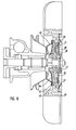
- Fig. 6 einen Axialschnitt einer weiteren Ausbildung des erfindungsgemäßen Ventilators,
- Fig. 7 einen Axialschnitt einer weiteren Ausbildung des erfindungsgemäßen Ventilators,
- Fig. 8,9,lo Teile des Balgs, wie er in dem in Fig. 7 gezeigten Ventilator verwendet ist,
- Fig. 11 eine Draufsicht auf den in Fig. lo gezeigten Balgteil,
- Fig. 12 Draufsicht auf den in Fig. 9 gezeigten Balgteil und
- Fig. 13 einen Querschnitt durch eine Ausbildung einer Folie, wie sie für den Balg gemäß der in Fig. 7 gezeigten Ausbildung des Ventilators verwendbar ist.
- Ein Gehäuse 1 einer Wasserpumpe ist in bekannter Weise mit einem Motor verbunden. Die Wasserpumpenwelle 2 ist mittels Kugellager 3 im Gehäuse 1 gelagert. Auf der Wasserpumpenwelle 2 ist ein Pumpenlaufrad 4 aufgepreßt. Eine Wellendichtung 5 trennt den Wasserraum vom Lagerteil. Auf die Wasserpumpenwelle 2 ist ferner eine Nabe 6 aufgepreßt, auf welcher eine aus Teilen 7 und 8 bestehende Keilriemenscheibe und eine zur Kupplung gehörige Gegenscheibe 9 mittels Nieten lo befestigt sind. Auf einem angesetzten Teil 11 der Pumpenwelle 2 ist ein Ventilator frei drehbar gelagert. Diese Lagerung kann in verschiedener Weise ausgeführt sein, beispielsweise ist ein Gleilager oder auch ein Nadellager möglich. Der Ventilator besteht aus dem inneren Nabenteil 18, welcher hier über die Kugellager 12 und 13 auf dem Teil 11 der Pumpenwelle 2 gelagert ist und einem ringförmigen äußeren Nabenteil 19, welcher Flügel 2o und 21 trägt. Die Anzahl und Ausführung der Flügel ist in der Praxis allgemein bekannt. Der Nabenteil 19 mit den Flügeln ist vorzugsweise aus Kunststoff gefertigt. Die beiden Kugellager 12 und 13 sind im vorliegenden Beispiel zur besseren Wärmeisolation gegenüber dem Teil 11 der Pumpenwelle 2 gewählt. Ein Sprengring 14, ein Distanzring 15 und ein Ringflansch 16 eines inneren Nabenteiles 18 des Ventilators bilden eine Klemmverbindung um den Ventilator gegen eine axiale Verschiebung zu sichern.
- Die Nabenteile 18 und 19 des Ventilators sind mit einem Thermostaten verbunden. Der Thermostat besteht aus einer stirnseitig fest angeordneten und dem Kühlluftstrom ausgesetzten metallischen Frontplatte 22, einem Faltenbalg 23 aus Metall und einer Grundplatte 24. Durch den Faltenbalg 23 wird zwischen der Frontplatte 22 und der Grundplatte 24 ein Hohlraum geschaffen, in den das Füllmedium eingefüllt werden kann.
- Der Faltenbalo23 ist, wie aus Fig. 3 ersichtlich, mit einem inneren und einem äußeren Balgteil 23 a,b ausgebildet. Diese beiden Teile 23 a, b sind mittels der ebenfalls metallischen Grundplatte 24 durch Verschweißen oder Verlöten gasdicht verbunden.
- Grundsätzlich ist es auch möglich den beschriebenen metallischen Faltenbalg mit der Grundplatte als Boden in'einem Stück herzustellen. Ob dies im Einzelfall vorzuziehen ist, ist aus Gründen der Wirtschaftlichkeit von Fall zu Fall durch einen Fachmann zu entscheiden.
- Die metallische Frontplatte 22 ist mit den Balgenden 32 und 33 (Fig.3) gasdicht, vorzugsweise durch Löten oder Schweißen verbunden. Bei dem inneren Balgende 32 genügt es allerdings auch schon, wenn man es, wie dargestellt, zusammen mit der Frontplatte 22 nur mit Hilfe einer Klemmverbindung mit dem inneren Nabenteil 18 drehfest und gasdicht verbindet.
- Eine solche Klemmverbindung besteht gemäß Fig. 1 aus einem Ring 26, einem Federring 27 (siehe auch Fig. 4 und 5) und einem Ring 28. Die Frontplatte 22 und der innere Balgrand 32 sind zusammen mit den genannten drei Ringen 26, 27 und 28 zwischen einen Fortsatz 25 des inneren Nabenteiles 18 und einen Sprengring 29 eingeklemmt. Zur Verbesserung der Wärmeisolation ist der Thermostat 22, 23, 24 in der Klemmvorrichtung 25, 26, 27, 28, 29 in einem Ringpaar 37 aus isolierendem Material gehalten. Die beschriebene Klemmvorrichtung kann auch durch eine geeignete Verschraubung ersetzt werden.
- Es hat sich gezeigt, daß die beschriebene Verbindung zwischen Balg 23 und Frontplatte 22 eine gute Wärmeleitfähigkeit liefert. Eine weitere Verbesserung des Wärmeaustausches mit einem durch einen Einfüllstutzen in den Faltenbalg 23 eingefüllten Füllmedium wird durch einen Ring 34 geschaffen. Dieser Ring 34 ist mit der Frontplatte 22 gut wärmeleitend verlötet oder verschweißt und ragt in das Innere des Faltenbalges 23.
- Neben seiner Aufgabe, die Wärme von der Frontplatte 22 gut und schnell in das Innere des Faltenbalges 23 zu leiten, hat der Ring 34 weiter die Aufgabe, ein unzulässiges Zusammendrücken des Faltenbalges zu verhindern. Seine Ausdehnung in Axialrichtung ist daher entsprechend dem zulässigen Mindestabstand zwischen Frontplatte 23 und Grundplatte 24 gewählt. Damit das Füllmedium vor und hinter den Räumen des Ringes 34 kommunizieren kann, weist der Ring längs seines Umfanges verteilt angeordnete Einschnitte 35 auf.
- Anstelle des Ringes 34 können auch einzelne Segmente ringförmig auf der Frontplatte 22 angeordnet sein. Auch andere Formen, wie radial verlaufende Rippen (nicht dargestellt) sind denkbar.
- Auf ihrer dem Kühlluftstrom ausgesetzten Oberfläche trägt die Frontplatte 22 Kühlrippen 36, die ebenfalls mit der Frontplatte 22 gut wärmeleitend verbunden sind. Die Frontplatte 22 kann hierzu, beispielsweise zusammen mit den Elementen 34 und 36, in einem Preß-oder Gießverfahren hergestellt sein.
- An den beschriebenen Thermostaten 22, 23, 24 ist der die Flügel 20, 21 tragende Nabenteil 19 angespritzt. Auf der zur Kupplung gehörenden Scheibe 9 ist ein Reibbelag 31 aus einem für Reibungskupplungen geeigneten Material befestigt. Dieser Reibbelag könnte auch auf der Grundplatte 24 des Thermostaten angebracht werden, doch ist dies nicht in einer Zeichnung dargestellt.
- Zwischen einem radial nach außen ragenden Ringflansch des Ringes 28 und der Grundplatte 24 befindet sich eine Tellerfeder 30. Mit dieser kann der auf das Füllmedium des Thermostaten wirkende Druck beeinflußt und auch die Eigenfederung des Faltenbalges berücksichtigt werden.
- Im Hohlraum des beschriebenen Thermostaten befindet sich, wie in der DE-PS 26 35 896 bereits beschrieben, eine Flüssigkeit, deren Siedepunkt ungefähr im Bereich 50° - 60° C liegt. Wenn der Siedepunkt tiefer liegt, kann dies mittels der Tellerfeder 3o ausgeglichen werden. Die Füllmenge der Flüssigkeit im Thermostaten wird so gewählt, daß über den ganzen Arbeitsbereich, also auch bei höchsten Betriebstemperaturen, immer eine bestimmte Menge Flüssigkeit unverdampft im Thermostaten verbleibt und somit vom Ventilator in Drehung mitgenommen wird. Diese verbleibende Flüssigkeitsmenge soll so bemessen sein, daß der durch ihre Fliehkraft erzeugte und auf den Kupplungsteil axial wirkende Anteil der Anpreßkraft allein nicht ausreicht, um das Kupplungs- und Drehmoment ohne temperaturbedingten Gasdruckanteil zu übertragen.
- Als Füllmedium kann beispielsweise Trichlortrifluor- äthan (C2C13F3), welches unter der Handelsbezeichnung "Frigen 113" bekannt ist, verwendet werden. Das Füllmedium kann auch aus zwei oder mehr verschiedenen Flüssigkeiten bestehen, wobei aber der Siedepunkt keiner der Stoffe wesentlich unter der gewünschten Einschalttemperatur des Thermostaten liegen soll.
- Während in Fig. 1 der Behälter des Thermostaten durch einen mehrere Wellen umfassenden Faltenbalg 23 gebildet ist, ist bei der in Fig. 6'gezeigten Ausbildungsform des erfindungsgemäßen Ventilators ein Metallbalg verwendet, der als Faltenbalg mit einer einzigen Welle bezeichnet werden kann.
- Der in Fig. 6 gezeigte Metallbalg ist aus zwei kreisringförmigen Schalen 38 und 39 gebildet, deren Ränder durch Löten oder Schweißen gasdicht verbunden sind, um einen konzentrisch um die innere Nabe 18 des Ventilators umlaufenden,ringförmigen Hohlraum 4o zu schaffen. Als gut wärmeleitendes Element ist hier ein Ring 41 vorgesehen, der mit der Frontplatte 42 gut wärmeleitend, vorzugsweise ebenfalls durch Löten oder Schweißen, verbunden ist. Am Umfang des Ringes 41 sind Nuten 43 eingelassen, um eine freie Zirkulation des Füllmediums im Hohlraum 4o zu ermöglichen. Ebenfalls mit der Frontplatte 42 ist auch die feste Wandung der Schale 38 verbunden.
- Sobald das Füllmedium im Hohlraum 4o des Thermostaten einen ausreichenden Druck aufweist, wird eine an der nachgiebigen Wandung der Schale 49 anliegende Druckplatte 44, deren von der Schale abliegende Oberfläche mit einem Reibbelag 45 versehen ist, an eine auf der Motorwelle 2 sitzende Gegenscheibe 46 gepreßt und damit der Ventilator im Kraftschluß angekoppelt. Die Druckplatte 44 sitzt axial verschieblich auf der inneren Ventilatornabe 47 und ist mit dieser mittels Zähnen und Nuten formschlüssig verbunden. Die ebenfalls auf der inneren Ventilatornabe 47 befestigte Frontplatte 42, die mit der äußeren, die Ventilatorflügel tragende Nabe 48, verbunden ist, bewirkt bei erfolgter Kupplung zwischen der Druckplatte 44 und der Gegenscheibe 46 die Rotation der Ventilatorflügel.
- Zur besseren Wärmeübertragung aus dem Kühlluftstrom an das im Thermostaten befindliche Füllmedium, sind in die Frontplatte 42 am Umfang verteilt Ausbuchtungen oder Fenster 49 eingebracht, über die die Kühlluft streichen kann,.um ihre Wärme an den Thermostaten zu übertragen. Die übrigen Konstruktionselemente entsprechen denen des Ausbildungsbeispieles 1 und brauchen hier nicht nochmals eigens aufgeführt zu werden. Ihre Bezugsziffern sind daher im Text mit diesen übereinstimmend gewählt worden.
- Bei dem in Fig. 7 gezeigten Ausführungsbeispiel ist der Thermostat durch einen als eine ringförmige Schale 61 ausgebildeten Balg gebildet, deren Ränder gasdicht unmittelbar mit der Frontplatte 5o verlötet oder verschweißt sind.
- Zur Erzielung einer ausreichenden Verschiebung der nachgiebigen Schalenwand bei Erhöhung des Druckes des Füllmediums, umfaßt die Schale 61 im Ausführungsbeispiel eine sehr dünne gasdichte Metallfolie (Fig.8) Diese Metallfolie 51 ist schalenförmig ausgebildet. Sie ist jedoch äußerst empfindlich gegen Druckveränderung und muß daher gegen Uberbeanspruchung durch Stütz- bzw. Schutzschalen bewehrt sein.
- In Fig. lo ist eine hierfür geeignete biegesteife ringförmige Stützschale 52 gezeigt, deren Form im wesentlichen der der Schale 51 entspricht. Ihre Fläche ist jedoch mit Schlitzen 59 versehen, um eine gute Zirkulation des Füllmediums im Schalen- bzw. Balginnenraum zu ermöglichen. Die Stützschale 52 ist ebenfalls aus Metall gefertigt und erfüllt gleichzeitig die Aufgabe einer guten Wärmeübertragung von der Frontplatte 5o an das Füllmedium. Ferner dient. sie als Abstandshalter zwischen der Frontplatte 5o und der Schale 51, um einen wählbaren Mindestabstand zwischen der Ringfläche der Schale 51 und der Frontplatte 5o zu gewährleisten. Die Schlitze 59 der Schale 52 verlaufen in radialer Richtung und haben die weitere Aufgabe, die Steifigkeit der Stützschale 52 zu verringern. Anstelle der Schlitze 59 können jedoch auch beliebig geformte Durchbrüche in beliebiger Anzahl und Anordnung gewählt sein.
- Während die Stützschale 52 die Aufgabe hat, die aus mindestens einer sehr dünnen Folie gebildete Schale 51 gegen eine Überbeanspruchung von außen zu sichern, dient eine weitere ringförmige Schale 53, welche als Schutzschale auf der äußeren Oberfläche der Schale 51 angeordnet ist, dazu, eine Uberbeanspru-' chung der Schale 51 durch erhöhten Innendruck zu verhindern. Die Schale 53 ist ebenfalls mit radial verlaufenden Schlitzen 60 oder anderen beliebig angeordneten Durchbrechungen. versehen, doch kann sie im Gegensatz zu der Stützschale 52 auch aus einem plastischen Material bestehen, so daß die bei Druckerhöhung des Füllmediums für die Kupplung erforderliche Hubbewegung der Schale 51 nicht behindert wird. Demgegenüber hat die biegesteife Stützschale 52 der Feder 54 Widerstand entgegenzusetzen.
- Die beschriebenen, im wesentlichen untereinander formgleichen Schalen 53, 51 und 52 werden in der genannten Reihenfolge übereinander geschoben und an ihren Rändern mit der Frontplatte 5b vereinigt. Dabei werden mindestens die aus Metall gebildeten Schalen 51 und 52 längs ihrer Randzonen mit der Frontplatte 5o gasdicht verlötet oder verschweißt.
- Eine besonders große Elastizität und gute Durchbiegungsfähigkeit bei Druckänderung im Inneren des Balgs erhält man, wenn man die Folien für die elastischen Schalen in ihrer Mittelzone entsprechend der im Querschnitt in Fig. 13 gezeigten Ausbildung 51a mit konzentrisch verlaufenden Rillen versieht.
- Es soll darauf hingewiesen werden, daß anstelle der Schutzfolie 53 auch eine Mehrzahl dünner Schalen 51 schichtartig miteinander vereinigt sein kann. Diese Ausbildungsform ist jedoch nicht zeichnerisch dargestellt. Bei dieser Ausbildung können eine oder mehrere Schalen 51 auch aus Kunststoff bestehen, sofern dafür gesorgt ist, daß mindestens eine Schale 51 eine gasdichte Verbindung mit der Frontplatte gewährleistet, was vorzugsweise durch Wahl einer metallischen Folie erreicht werden kann.
- Die Schale 53 kann, da sie keine Dichtungsfunktion ausübt, zur Erzielung einer guten Elastizität ebenfalls aus Kunststoff bestehen. Lediglich die Platte 52, die neben ihrer Stützfunktion auch noch die Aufgabe einer guten Wärmeübertragung von der Frontplatte zum Füllmedium zu erfüllen hat, sollte aus einem metallischen Werkstoff gefertigt sein. Für die Druckübertragung ist auch bei der in Fig. 7 gezeigten Ausbildungsform eine Druckplatte 55 vorgesehen, die mit dem äußeren Nabenteil 56 des Ventilators mittels Zähnen 57 und Nuten 58 formschlüssig verbunden ist.
- Die Wirkungsweise des selbsttätig schaltbaren Ventilators ist folgende:
- Wenn der beschriebene Ventilator hinter einem Fahrzeugkühler angeordnet und über die Keilriemenscheibe 7, 8 vom Motor angetrieben wird, ist bei Beginn des Betriebes der Ventilator vorerst nicht mit der Welle 11 gekuppelt und steht fast still. Allmählich wird die durch den Kühler strömende, angewärmte Luft auf den Thermostaten einwirken; eine solche Luftströmung entsteht schon bei geringer Fahrgeschwindigkeit, ja schon durch die Schleppdrehzahl des Ventilators. Bei steigender Temperatur der Kühlluftströmung wird auch der Thermostat auf höhere . Temperatur gebracht und bei Erreichung der zugehörigen Temperatur beginnt das Füllmedium im Thermostaten zu sieden, wobei sich bei stetiger Wärmezufuhr im Thermostaten ein Gasdruck aufbaut, der den nachgiebigen=Teil des Faltenbalges nach links (in Fig. 1) drückt, wodurch unter überwindung der Kraft der Feder 3o die Grundplatte 24 des Thermostaten an die vom Motor angetriebene Kupplungsgegenscheibe 9 drückt. Infolge des einsetzenden Kraftschlusses wird der Ventilator und der mit diesem verbundene Thermostat in entsprechende Drehung versetzt. Die im Thermostaten befindliche Flüssigkeit wird ebenfalls in Drehung versetzt und die dadurch entstehende Fliehkraft drückt mit ihrer Axialkomponente auf die nachgiebige Grundplatte 24 des Thermostaten und übt damit einen zusätzlichen Druck auf die Kupplungsgegenscheibe 9 mit dem Reibbelag 31 aus, was zusammen mit dem Gasdruck die Übertragung des Drehmomentes bewirkt.
- Solange die Kühllufttemperatur über dem Normalwert liegt, wird dieser Zustand erhalten bleiben und es tritt eine intensive Kühlung durch den Ventilator ein. Sinkt nun die Kühllufttemperatur auf einen Wert ab, der in der Nähe..der Siedetemperatur des Füllmediums liegt, so verschwindet auch der im Thermostaten wirkende Gasdruck und es bleibt nur der von der Flüssigkeit erzeugte Fliehkraftdruckanteil übrig, der aber allein nicht ausreicht, das Ventilator-Drehmoment in allen Betriebsbereichen zu übertragen. Reißt in irgendeinem Betriebszustand die Kupplung nur einen Moment ab, so sinkt sofort die Ventilatordrehzahl und der von der Fliehkraft erzeugte Druckanteil bricht rasch zusammen, da er dem Quadrat der Umdrehungsgeschwindigkeit direkt proportional ist. Hierzu kommt noch, daß im Moment, in dem die Kupplung zu schlüpfen beginnt, an.dem Reibbelag 31 der dynamische Reibwert maßgeblich wird, welcher aber wesentlich kleiner ist als der statische Reibwert (Haftreibung). Damit ist ein rasches, praktisch schlupfloses Abschalten der Kupplung gewährleistet.
- Die im Zusammenhang mit Fig. 1 beschriebene Arbeitsweise des Ventilators entspricht im wesentlichen auch der der in den Fig. 6 und 7 gezeigten Ausbildungsformen, so daß auf diese nicht mehr im einzelnen eingegangen werden muß..
Claims (15)
Priority Applications (1)
| Application Number | Priority Date | Filing Date | Title |
|---|---|---|---|
| AT81109753T ATE19290T1 (de) | 1980-11-21 | 1981-11-19 | Selbsttaetig schaltbarer ventilator fuer kuehlsysteme von verbrennungsmotoren. |
Applications Claiming Priority (2)
| Application Number | Priority Date | Filing Date | Title |
|---|---|---|---|
| DE3043929 | 1980-11-21 | ||
| DE19803043929 DE3043929A1 (de) | 1980-11-21 | 1980-11-21 | "selbsttaetig schaltbarer ventilator fuer kuehlsysteme von verbrennungsmotoren" |
Publications (2)
| Publication Number | Publication Date |
|---|---|
| EP0052859A1 true EP0052859A1 (de) | 1982-06-02 |
| EP0052859B1 EP0052859B1 (de) | 1986-04-16 |
Family
ID=6117274
Family Applications (1)
| Application Number | Title | Priority Date | Filing Date |
|---|---|---|---|
| EP81109753A Expired EP0052859B1 (de) | 1980-11-21 | 1981-11-19 | Selbsttätig schaltbarer Ventilator für Kühlsysteme von Verbrennungsmotoren |
Country Status (5)
| Country | Link |
|---|---|
| EP (1) | EP0052859B1 (de) |
| JP (1) | JPS57502010A (de) |
| AT (1) | ATE19290T1 (de) |
| DE (2) | DE3043929A1 (de) |
| WO (1) | WO1982001740A1 (de) |
Cited By (1)
| Publication number | Priority date | Publication date | Assignee | Title |
|---|---|---|---|---|
| EP0451451A1 (de) * | 1990-04-12 | 1991-10-16 | Anton Ryba | Selbsttätig schaltbarer Ventilator für das Kühlsystem von Kraftfahrzeugen |
Families Citing this family (1)
| Publication number | Priority date | Publication date | Assignee | Title |
|---|---|---|---|---|
| DE102006011119B4 (de) * | 2006-03-08 | 2016-05-25 | Karl Heinz Linnig Gmbh & Co. Kg | Kupplungsanordnung mit Wärmeausdehnungskupplung |
Citations (7)
| Publication number | Priority date | Publication date | Assignee | Title |
|---|---|---|---|---|
| US2273306A (en) * | 1940-01-30 | 1942-02-17 | Clifford Mfg Co | Thermostatically controlled unit |
| US2487946A (en) * | 1945-06-14 | 1949-11-15 | Jurg A Senn | Thermal responsive device and mounting therefor |
| FR1261720A (fr) * | 1960-07-04 | 1961-05-19 | Thompson Ramo Wooldridge Inc | Accouplement sensible à la température |
| GB958138A (en) * | 1961-04-21 | 1964-05-13 | Smith & Sons Ltd S | Improvements in or relating to clutches controlled by heat responsive means |
| US3180325A (en) * | 1962-06-08 | 1965-04-27 | Roy L Neuhauser | Thermally responsive clutch assembly |
| US3797316A (en) * | 1971-12-22 | 1974-03-19 | Bailey Meter Co | Bellows temperature bulb sensor |
| FR2328866A1 (fr) * | 1975-10-22 | 1977-05-20 | Auve Patentverwertung Gmbh | Ventilateur a commande automatique |
Family Cites Families (2)
| Publication number | Priority date | Publication date | Assignee | Title |
|---|---|---|---|---|
| US1233518A (en) * | 1916-04-18 | 1917-07-17 | Ross J Beatty | Automatically-controlled fan. |
| US3135495A (en) * | 1961-11-24 | 1964-06-02 | Kysor Heater Company | Thermostatic control valve |
-
1980
- 1980-11-21 DE DE19803043929 patent/DE3043929A1/de not_active Ceased
-
1981
- 1981-11-19 WO PCT/EP1981/000181 patent/WO1982001740A1/de not_active Ceased
- 1981-11-19 AT AT81109753T patent/ATE19290T1/de not_active IP Right Cessation
- 1981-11-19 JP JP56503684A patent/JPS57502010A/ja active Pending
- 1981-11-19 EP EP81109753A patent/EP0052859B1/de not_active Expired
- 1981-11-19 DE DE8181109753T patent/DE3174418D1/de not_active Expired
Patent Citations (7)
| Publication number | Priority date | Publication date | Assignee | Title |
|---|---|---|---|---|
| US2273306A (en) * | 1940-01-30 | 1942-02-17 | Clifford Mfg Co | Thermostatically controlled unit |
| US2487946A (en) * | 1945-06-14 | 1949-11-15 | Jurg A Senn | Thermal responsive device and mounting therefor |
| FR1261720A (fr) * | 1960-07-04 | 1961-05-19 | Thompson Ramo Wooldridge Inc | Accouplement sensible à la température |
| GB958138A (en) * | 1961-04-21 | 1964-05-13 | Smith & Sons Ltd S | Improvements in or relating to clutches controlled by heat responsive means |
| US3180325A (en) * | 1962-06-08 | 1965-04-27 | Roy L Neuhauser | Thermally responsive clutch assembly |
| US3797316A (en) * | 1971-12-22 | 1974-03-19 | Bailey Meter Co | Bellows temperature bulb sensor |
| FR2328866A1 (fr) * | 1975-10-22 | 1977-05-20 | Auve Patentverwertung Gmbh | Ventilateur a commande automatique |
Cited By (1)
| Publication number | Priority date | Publication date | Assignee | Title |
|---|---|---|---|---|
| EP0451451A1 (de) * | 1990-04-12 | 1991-10-16 | Anton Ryba | Selbsttätig schaltbarer Ventilator für das Kühlsystem von Kraftfahrzeugen |
Also Published As
| Publication number | Publication date |
|---|---|
| EP0052859B1 (de) | 1986-04-16 |
| DE3043929A1 (de) | 1982-05-27 |
| DE3174418D1 (en) | 1986-05-22 |
| JPS57502010A (de) | 1982-11-11 |
| ATE19290T1 (de) | 1986-05-15 |
| WO1982001740A1 (en) | 1982-05-27 |
Similar Documents
| Publication | Publication Date | Title |
|---|---|---|
| EP0687584B1 (de) | Heizvorrichtung für Kraftfahrzeuge | |
| DE4390685C2 (de) | Temperaturabhängig betätigbare Flüssigkeitsreibungskupplung für einen Ventilator | |
| DE3144495C2 (de) | Flüssigkeitsreibungskupplung | |
| DE2444843C2 (de) | Spiralförmige Drehdichtung mit einem Fluid zur Abdichtung einer rotierenden Welle | |
| DE2212367A1 (de) | Fluessigkeitsreibungskupplung, insbesondere fuer den luefterantrieb bei brennkraftmaschinen | |
| DE2408660B2 (de) | Doppelt wirkende Gleitringdichtung | |
| DE4038485C2 (de) | Temperaturempfindliche Flüssigkeitreibungskupplung | |
| DE4104928C2 (de) | Temperaturgesteuerte Ventilatorflüssigkeitskupplung | |
| DE2635896C3 (de) | Selbsttätig schaltbarer Ventilator, insbesonders für Kühlsysteme von Verbrennungsmotoren | |
| DE1286842B (de) | Fluessigkeitsreibungskupplung | |
| DE2553661A1 (de) | Viskositaetskupplung | |
| DE1939402U (de) | Fluessigkeitskupplung. | |
| DE1284186B (de) | Fluessigkeitsreibungskupplung | |
| DE4103319C2 (de) | Viskofluidkupplung | |
| DE3635627C2 (de) | Flüssigkeitsreibungskupplung | |
| DE2814608B2 (de) | Flüssigkeitsreibungskupplung | |
| DE1284187B (de) | Fluessigkeitsreibungskupplung mit Fuellungsregelung zum Antrieb von Geblaesen | |
| EP0052859A1 (de) | Selbsttätig schaltbarer Ventilator für Kühlsysteme von Verbrennungsmotoren | |
| DE4125396A1 (de) | Temperaturgesteuerte fluidreibkupplung | |
| EP0134548A2 (de) | Flüssigkeitsreibungskupplung | |
| EP0451451B1 (de) | Selbsttätig schaltbarer Ventilator für das Kühlsystem von Kraftfahrzeugen | |
| DE4125397A1 (de) | Temperaturgesteuerte fluidreibkupplung | |
| DE8133775U1 (de) | Selbsttaetig schaltbarer ventilator fuer kuehlsysteme von verbrennungsmotoren | |
| DE69837065T2 (de) | Abdichtung für Explosionsgeschützte Motoren | |
| DE3518931A1 (de) | Fluessigkeits-luefterkupplung fuer kraftfahrzeuge mit temperaturabhaengig veraenderbarem pumpspalt |
Legal Events
| Date | Code | Title | Description |
|---|---|---|---|
| PUAI | Public reference made under article 153(3) epc to a published international application that has entered the european phase |
Free format text: ORIGINAL CODE: 0009012 |
|
| AK | Designated contracting states |
Designated state(s): AT DE FR GB IT NL SE |
|
| 17P | Request for examination filed |
Effective date: 19820513 |
|
| GRAA | (expected) grant |
Free format text: ORIGINAL CODE: 0009210 |
|
| AK | Designated contracting states |
Kind code of ref document: B1 Designated state(s): AT DE FR GB IT NL SE |
|
| PG25 | Lapsed in a contracting state [announced via postgrant information from national office to epo] |
Ref country code: NL Effective date: 19860416 Ref country code: IT Free format text: LAPSE BECAUSE OF FAILURE TO SUBMIT A TRANSLATION OF THE DESCRIPTION OR TO PAY THE FEE WITHIN THE PRESCRIBED TIME-LIMIT;WARNING: LAPSES OF ITALIAN PATENTS WITH EFFECTIVE DATE BEFORE 2007 MAY HAVE OCCURRED AT ANY TIME BEFORE 2007. THE CORRECT EFFECTIVE DATE MAY BE DIFFERENT FROM THE ONE RECORDED. Effective date: 19860416 Ref country code: FR Free format text: THE PATENT HAS BEEN ANNULLED BY A DECISION OF A NATIONAL AUTHORITY Effective date: 19860416 |
|
| REF | Corresponds to: |
Ref document number: 19290 Country of ref document: AT Date of ref document: 19860515 Kind code of ref document: T |
|
| PG25 | Lapsed in a contracting state [announced via postgrant information from national office to epo] |
Ref country code: SE Effective date: 19860430 |
|
| REF | Corresponds to: |
Ref document number: 3174418 Country of ref document: DE Date of ref document: 19860522 |
|
| RAP2 | Party data changed (patent owner data changed or rights of a patent transferred) |
Owner name: AUVE PATENTVERWERTUNGS GMBH |
|
| EN | Fr: translation not filed | ||
| NLV1 | Nl: lapsed or annulled due to failure to fulfill the requirements of art. 29p and 29m of the patents act | ||
| PG25 | Lapsed in a contracting state [announced via postgrant information from national office to epo] |
Ref country code: AT Effective date: 19861119 |
|
| PLBE | No opposition filed within time limit |
Free format text: ORIGINAL CODE: 0009261 |
|
| STAA | Information on the status of an ep patent application or granted ep patent |
Free format text: STATUS: NO OPPOSITION FILED WITHIN TIME LIMIT |
|
| 26N | No opposition filed | ||
| GBPC | Gb: european patent ceased through non-payment of renewal fee | ||
| PG25 | Lapsed in a contracting state [announced via postgrant information from national office to epo] |
Ref country code: DE Effective date: 19870801 |
|
| PG25 | Lapsed in a contracting state [announced via postgrant information from national office to epo] |
Ref country code: GB Effective date: 19881118 |