EP0052875A2 - Tiroir en matière plastique - Google Patents
Tiroir en matière plastique Download PDFInfo
- Publication number
- EP0052875A2 EP0052875A2 EP81109814A EP81109814A EP0052875A2 EP 0052875 A2 EP0052875 A2 EP 0052875A2 EP 81109814 A EP81109814 A EP 81109814A EP 81109814 A EP81109814 A EP 81109814A EP 0052875 A2 EP0052875 A2 EP 0052875A2
- Authority
- EP
- European Patent Office
- Prior art keywords
- components according
- outer shell
- drawer
- strip
- groove
- Prior art date
- Legal status (The legal status is an assumption and is not a legal conclusion. Google has not performed a legal analysis and makes no representation as to the accuracy of the status listed.)
- Granted
Links
Images


Classifications
-
- A—HUMAN NECESSITIES
- A47—FURNITURE; DOMESTIC ARTICLES OR APPLIANCES; COFFEE MILLS; SPICE MILLS; SUCTION CLEANERS IN GENERAL
- A47B—TABLES; DESKS; OFFICE FURNITURE; CABINETS; DRAWERS; GENERAL DETAILS OF FURNITURE
- A47B88/00—Drawers for tables, cabinets or like furniture; Guides for drawers
- A47B88/90—Constructional details of drawers
- A47B88/941—Drawers being constructed from two or more parts
-
- A—HUMAN NECESSITIES
- A47—FURNITURE; DOMESTIC ARTICLES OR APPLIANCES; COFFEE MILLS; SPICE MILLS; SUCTION CLEANERS IN GENERAL
- A47B—TABLES; DESKS; OFFICE FURNITURE; CABINETS; DRAWERS; GENERAL DETAILS OF FURNITURE
- A47B2210/00—General construction of drawers, guides and guide devices
- A47B2210/02—Drawers with hollow lateral walls in two parts
Definitions
- the invention relates to plastic components for the production of a drawer, consisting of side walls, which have at the rear end at right angles projecting pins for inserting a plastic rear wall with a chamber profile, the side walls being composed of two parts and smooth inside and outside and at the lower inner edge with a groove for receiving an inserted drawer bottom are provided.
- an easily assembled furniture part preferably a drawer, which has hollow walls which are composed of two shell-shaped wall parts, each with an externally smooth wall surface, which wall parts have integrally molded and thus assigned and designed webs and recesses on the mutually facing surfaces, that the webs in the Engage recesses and hold the wall parts together with barbs, in which furniture part are arranged on one of two adjacent walls in the region of one edge, connecting pins which engage from the front side in the cavity of the other wall, where the connecting pins are integral with one of the wall parts are formed and wherein one of the wall parts of the wall having the connecting pin, the end faces of which has strips (DB-PS 19 57 878).
- a drawer is known with a drawer body which is at least double-walled on the sides and molded in one piece from plastic, in which shortened transverse ribs are provided in the space between the double walls of the sides with respect to the inner side wall, with a transverse wall from below insert extending to the wall is inserted in a form-fitting manner, the lower part of which has a holder for a guide which is open to the side, and in which the walls of the drawer body surrounding the intermediate space are continuously smooth, in which the insert used as a rib strip is inserted in the intermediate space is formed, which contains the transverse ribs in its upper part and, viewed in the longitudinal direction, has transversely offset fields which alternately abut the inner surfaces of the outer side wall and the inner side wall and are connected by transverse ribs, and in which the rib strip in its u lower part for the guide has a receptacle in the form of an insert groove (DAS 27 08 167).
- DAS 27 08 167 receptacle in the
- the object of the invention is to improve and further develop components for producing a drawer according to the prior art described in the first place, so that a drawer can be produced therefrom which has the advantages of the drawer described above but the disadvantages thereof, in particular, avoiding their one-piece construction, which requires a large transport and storage volume, but instead only a very small transport and storage space needed.
- the drawer according to the invention should be easy and simple to assemble from components, and in particular should also offer the possibility of representing any width dimensions with very low mold and manufacturing costs.
- the groove for inserting the drawer bottom is formed on its top by an inwardly projecting molding of the outer shell and on its underside by a strip on the rib strip projecting parallel to it.
- This projecting bar is advantageously partially interrupted.
- the inwardly projecting molding of the outer shell is expediently designed as a lip with a profile tapering towards its outer edge.
- the projecting ledge on the rib ledge is provided with openings at intervals to accommodate tongues projecting downward on the associated lower edge of the outer shell. According to an advantageous further development, these tongues can be provided with underlap formations, which are preferably mushroom-shaped.
- the material or wall thickness of the outer shell can also be kept relatively very small, so that the component can be produced at lower cost due to the lower outlay on feed material.
- the formation of the outer shell, which forms the upper longitudinal edge and the two outer walls in one piece, avoids joints which are disadvantageous both in terms of manufacture and in particular in use.
- the formation of the groove near the lower inner edge for inserting the drawer bottom is ensured that the load on the drawer, which essentially stresses the drawer, is passed on in the shortest possible way to the drawer guides and thus to the furniture frame.
- the groove is formed by the two nested parts that form the side wall, namely the underside of the groove on which the drawer base rests is formed by the ribbed insert on which the drawer guides are also attached.
- the upper limit of the Groove is formed on the outer shell of the side wall, so that here there is only a single joint between this smooth-walled side wall shell and the floor, which joint can be kept particularly small and narrow and therefore tight by special shaping of the transition.
- connecting means By arranging connecting means along the entire length of the two parts to be inserted into each other, this position of the two parts relative to one another is fixed in a controllable manner, so that it is possible to glue or weld the two parts to one another, by designing the connecting means as form-fitting connecting means such welding or gluing can also be dispensed with, it will also result in the transfer of forces improved due to the load on the drawer bottom.
- the formation of the groove for receiving the drawer bottom between the two inner lower edges of the gutter shell and the ribbed strip not only offers the advantages already mentioned, but it can also be designed such that a drawer assembled with components according to the invention is variable in height by Instead of the plate-shaped drawer bottom, a tub which is preferably deep-drawn from plastic is used. Since the inner walls of the components forming the drawer run obliquely downwards anyway, that is to say these components become wider towards their base, the side walls of the one-piece trough used instead of the plate-shaped base are also to be designed to run obliquely. This offers the possibility of stacking these trough-shaped parts in a space-saving manner for shipping and storage.
- the components according to the invention are characterized in that the connecting pins for the rear wall are formed on an angled portion of the rear end of the outer shell.
- Dowels can be formed on the front end of the outer shell or on the ribbed strip for attaching a panel made of wood-based material.
- the connecting pins advantageously have a U-profile that is open towards the horizontal.
- the connecting pin is advantageous in the U-profile Shaped pin parallel to the legs of the U in the middle of the base of the U, which projects above the legs.
- the pins can be supported by stiffening ribs to the U-legs and to the U-base.
- the pins in the area in which they freely protrude from the U-profile of the pins are advantageously provided with a lateral inclined surface which lies towards the open end of the pins.
- the walls with a chamber profile that can be plugged onto the pegs have openings in their wall assigned to the pins.
- These mounting openings are expediently designed such that wide, circularly delimited holes are arranged on the outer shell and elongated holes are arranged on the insert at the bend in the ribbed strip, which are aligned with the aforementioned holes. Screws for fastening the drawer panel made of wood-based material are put through the two holes, the screw head rests on the elongated holes and engages behind them, so that an adjustment and adjustment of the panel with respect to the drawer or for alignment with adjacent furniture fronts is made possible. It goes without saying. it is possible to provide other known connecting means for attaching the drawer panel at the front end of the side walls, in particular those connecting means which allow the panel to be adjusted in height and to the side and then fixed.
- the plastic injection molded parts require the greatest effort in terms of molds and manufacture. According to the invention, the proportion of these components in a drawer is considerably reduced compared to previously known plastic drawers. This means that manufacturing is considerably more cost-effective. There is another advantage in terms of manufacturing costs in that both the width and the height can be changed within very wide limits with very simple measures, without the need for additional or other molding tools for injection molded parts. With a set of injection molding tools, components for a certain drawer depth can be produced according to the invention, with which all desired or occurring drawer widths and heights can be carried out. Since only a few different drawer depths are standardized in the furniture industry, a significant simplification has been achieved with the components according to the invention and, in particular, a considerable reduction in the general manufacturing costs.
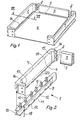
- the above-described design of the side wall 8- has a groove 13 open to the side for inserting guide rails, which in turn form the direct connection to the furniture frame.
- This design is also particularly suitable for inserting a plate-shaped drawer bottom 6 into the groove 4.
- the components can so be formed that are provided both at the front and at the rear of the side panels 1 with angled portions and pin 2 'so that a four-sided drawer arises whose serving to form the side parts of the cup-shaped AuBen inconvenience and ribs bars inserted, both made by injection molding, while the front and rear walls 3 consist of chamber profiles which are produced by the extrusion process and are cut to any desired or prescribed length, so that drawers of any width can be produced.
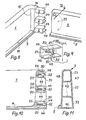
- the side parts 1 are provided with front bends 16, which are shown for the outer shell in FIGS. 12 and 14.
- the bend 16 has one continuous inner wall 54 on which the lip 19 is formed, which forms the top of the groove 4.
- the outer wall forms a circumferential flange 55 on the outside, 56 on the top and 57 on the inside.
- the flange 55 ends with the lower edge of the outer part 32 of the outer wall and can be provided there with a hook 58 for further positive connection with the inserted rib strip 8.
- the hook 58 engages behind the outer edge 31 of the crossbar 29 of the rib strip.
- the bend 16 is further provided on its continuous inner wall 54 with two circular openings 59 which are expediently one above the other.
- the bend 18 on the rib strip 8 lies behind the flanges 55, 56 and 57 of the bend 16 of the bowl-shaped part when the rib strip is inserted into the shell-shaped outer part 7 and is thereby secured.
- elongated holes 6o are arranged, which are aligned with the openings 59 and serve as abutments for screw heads of screws with which the drawer panel is fastened.
- This drawer cover is made of wood-based material and is designed in accordance with the usual furniture walls. Due to the arrangement of the elongated holes 6o, it is possible to align the screws and thus the panel before finally tightening to adjust the panel with respect to the drawer or with respect to neighboring furniture panels. If the screw shafts have a smaller diameter than corresponds to the small diameter of the elongated holes 6o, alignment both to the side and to the height is possible.
- the lower edge 61 of the front bend 18 of the rib strip is provided with a recess. 14 can already be seen that below the lip 19 the groove formed on the side walls is not present.
- the drawer bottom is guided below the bends 16 and 18 and the lip 19 through the recess in the lower edge 61 in FIG a corresponding groove, which is provided on the drawer cover to be attached, in order to also get hold on the front.
Landscapes
- Drawers Of Furniture (AREA)
- Compositions Of Macromolecular Compounds (AREA)
- Dental Preparations (AREA)
- Springs (AREA)
- Apparatuses And Processes For Manufacturing Resistors (AREA)
- Sampling And Sample Adjustment (AREA)
Priority Applications (1)
| Application Number | Priority Date | Filing Date | Title |
|---|---|---|---|
| AT81109814T ATE17821T1 (de) | 1980-11-26 | 1981-11-21 | Schublade aus kunststoff. |
Applications Claiming Priority (2)
| Application Number | Priority Date | Filing Date | Title |
|---|---|---|---|
| DE3044471 | 1980-11-26 | ||
| DE3044471A DE3044471C2 (de) | 1980-11-26 | 1980-11-26 | Schublade aus Kunststoff |
Publications (3)
| Publication Number | Publication Date |
|---|---|
| EP0052875A2 true EP0052875A2 (fr) | 1982-06-02 |
| EP0052875A3 EP0052875A3 (en) | 1982-09-01 |
| EP0052875B1 EP0052875B1 (fr) | 1986-02-05 |
Family
ID=6117593
Family Applications (1)
| Application Number | Title | Priority Date | Filing Date |
|---|---|---|---|
| EP81109814A Expired EP0052875B1 (fr) | 1980-11-26 | 1981-11-21 | Tiroir en matière plastique |
Country Status (4)
| Country | Link |
|---|---|
| EP (1) | EP0052875B1 (fr) |
| AT (1) | ATE17821T1 (fr) |
| DE (1) | DE3044471C2 (fr) |
| GB (1) | GB2087715B (fr) |
Cited By (4)
| Publication number | Priority date | Publication date | Assignee | Title |
|---|---|---|---|---|
| AT403648B (de) * | 1993-03-30 | 1998-04-27 | Blum Gmbh Julius | Schubladenbausatz |
| ITMI20111659A1 (it) * | 2011-09-15 | 2013-03-16 | Stefano Cantoni | Sistema di protezione perfezionato di mobili per dispositivi automatici di transazioni commerciali. |
| WO2015091125A3 (fr) * | 2013-12-20 | 2015-08-06 | Grass Gmbh | Tiroir de meuble et élément de paroi de tiroir pour un tiroir |
| CN106901524A (zh) * | 2017-04-18 | 2017-06-30 | 广东精诺五金实业有限公司 | 一种抽屉滑轨 |
Families Citing this family (10)
| Publication number | Priority date | Publication date | Assignee | Title |
|---|---|---|---|---|
| AT391253B (de) * | 1986-05-14 | 1990-09-10 | Blum Gmbh Julius | Beschlagbausatz fuer eine aus mehreren teilen zusammensetzbare schublade |
| DE8909926U1 (de) * | 1989-08-18 | 1989-12-14 | Kröger, Matthias, Bassano del Grappa | Möbelstück mit Schubladen |
| DE4200581C1 (fr) * | 1992-01-11 | 1993-07-29 | Mepla-Werke Lautenschlaeger Gmbh & Co Kg, 6107 Reinheim, De | |
| AT314U1 (de) * | 1994-10-05 | 1995-08-25 | Blum Gmbh Julius | Schubladenbausatz |
| AT404219B (de) * | 1995-01-19 | 1998-09-25 | Blum Gmbh Julius | Schublade |
| AT407332B (de) * | 1997-03-21 | 2001-02-26 | Blum Gmbh Julius | Schublade |
| DE10025951A1 (de) * | 2000-05-26 | 2001-11-29 | Hettich Paul Gmbh & Co | Befestigungsanordnung |
| DE102006052675A1 (de) * | 2006-11-07 | 2008-05-08 | Thomas Pollmeier | Ventilations-Rahmenelement |
| DE102009025791A1 (de) * | 2009-05-13 | 2010-11-18 | Paul Hettich Gmbh & Co. Kg | Schubkasten mit zwei Seitenwänden und einer Rückwand |
| DE202014006965U1 (de) * | 2014-08-27 | 2015-11-30 | Grass Gmbh | Vorrichtung zur Befestigung einer Seitenabdeckung an einem Blendenprofil eines bewegbaren Möbelteils |
Family Cites Families (6)
| Publication number | Priority date | Publication date | Assignee | Title |
|---|---|---|---|---|
| GB1189907A (en) * | 1967-10-16 | 1970-04-29 | Leslie William Llewelly Alston | Improvements in or relating to Drawers for Furniture |
| GB1190650A (en) * | 1967-11-08 | 1970-05-06 | Leslie William Llwellyn Alston | Improvements in or relating to Drawers for Furniture. |
| DE1957878C3 (de) * | 1969-11-18 | 1974-01-10 | Hans-Werner 4830 Guetersloh Duepree | Leicht zusammensetzbares Möbelteil, das hohle Wände aufweist |
| AU514291B2 (en) * | 1976-04-09 | 1981-02-05 | MACKENZIE KING HOLDINGS LIMITED and FORMICA LIMITED | Assembly of components into a drawer |
| DE2708167C3 (de) * | 1977-02-25 | 1985-04-04 | Düpree, Hans-Werner, 4830 Gütersloh | Schublade aus Kunststoff |
| DE2722465A1 (de) * | 1977-05-18 | 1978-11-23 | Miele & Cie | Schubkasten fuer wohn- und kuechenmoebel o.dgl. |
-
1980
- 1980-11-26 DE DE3044471A patent/DE3044471C2/de not_active Expired
-
1981
- 1981-11-21 AT AT81109814T patent/ATE17821T1/de not_active IP Right Cessation
- 1981-11-21 EP EP81109814A patent/EP0052875B1/fr not_active Expired
- 1981-11-25 GB GB8135465A patent/GB2087715B/en not_active Expired
Cited By (7)
| Publication number | Priority date | Publication date | Assignee | Title |
|---|---|---|---|---|
| AT403648B (de) * | 1993-03-30 | 1998-04-27 | Blum Gmbh Julius | Schubladenbausatz |
| ITMI20111659A1 (it) * | 2011-09-15 | 2013-03-16 | Stefano Cantoni | Sistema di protezione perfezionato di mobili per dispositivi automatici di transazioni commerciali. |
| WO2015091125A3 (fr) * | 2013-12-20 | 2015-08-06 | Grass Gmbh | Tiroir de meuble et élément de paroi de tiroir pour un tiroir |
| CN105848524A (zh) * | 2013-12-20 | 2016-08-10 | 格拉斯有限公司 | 家具抽屉和用于抽屉的抽屉壁元件 |
| CN105848524B (zh) * | 2013-12-20 | 2018-09-25 | 格拉斯有限公司 | 家具抽屉和用于抽屉的抽屉壁元件 |
| CN106901524A (zh) * | 2017-04-18 | 2017-06-30 | 广东精诺五金实业有限公司 | 一种抽屉滑轨 |
| CN106901524B (zh) * | 2017-04-18 | 2024-05-10 | 广东精诺五金实业有限公司 | 一种抽屉滑轨 |
Also Published As
| Publication number | Publication date |
|---|---|
| ATE17821T1 (de) | 1986-02-15 |
| GB2087715B (en) | 1985-10-16 |
| GB2087715A (en) | 1982-06-03 |
| EP0052875A3 (en) | 1982-09-01 |
| EP0052875B1 (fr) | 1986-02-05 |
| DE3044471A1 (de) | 1982-07-08 |
| DE3044471C2 (de) | 1986-10-30 |
Similar Documents
| Publication | Publication Date | Title |
|---|---|---|
| DE2708167C3 (de) | Schublade aus Kunststoff | |
| EP0052875B1 (fr) | Tiroir en matière plastique | |
| DE1554189A1 (de) | Systembauteile | |
| DE3441500C2 (de) | Regalboden aus Schichtwerkstoff, insbesondere Metallblech | |
| EP2767483B1 (fr) | Récipient de transport empilable | |
| DE7711771U1 (de) | Bausatz fuer regale o.dgl. | |
| EP1228719B1 (fr) | Tiroir avec façade amovible | |
| CH677867A5 (fr) | ||
| DE2309573A1 (de) | Grundelement eines moebelsystems | |
| EP3753857A1 (fr) | Élément de paroi d'un cadre de rehausse de palette et cadre de rehausse de palette | |
| DE19620709C5 (de) | Möbelfußsystem | |
| DE3516409C2 (fr) | ||
| DE8810830U1 (de) | Trennwand zur Unterteilung von Abstell- und/oder Ablageflächen | |
| DE8529412U1 (de) | Regal mit Regalböden aus Schichtwerkstoff, insbesondere Metallblech | |
| DE9105237U1 (de) | Blechschubkasten | |
| DE20009471U1 (de) | Modulares Unterteilungssystem für Schubkästen | |
| EP0276668B1 (fr) | Tiroir | |
| EP0348789A2 (fr) | Plateau pour formulaires | |
| EP0331989A1 (fr) | Caisse de stockage et/ou de transport | |
| DE8426728U1 (de) | Sortier-Kasten | |
| DE29707568U1 (de) | Auszug für Möbel o.dgl., insbesondere für Büromöbel | |
| DE2338570A1 (de) | Aus seitenwaenden und einem boden zusammengesetzter container aus blech | |
| DE7705784U1 (de) | Schublade aus kunststoff | |
| DE1265647B (de) | Behaelter | |
| DE3643068A1 (de) | Schublade |
Legal Events
| Date | Code | Title | Description |
|---|---|---|---|
| PUAI | Public reference made under article 153(3) epc to a published international application that has entered the european phase |
Free format text: ORIGINAL CODE: 0009012 |
|
| AK | Designated contracting states |
Designated state(s): AT BE CH FR IT NL SE |
|
| PUAL | Search report despatched |
Free format text: ORIGINAL CODE: 0009013 |
|
| AK | Designated contracting states |
Designated state(s): AT BE CH FR IT NL SE |
|
| 17P | Request for examination filed |
Effective date: 19830218 |
|
| ITF | It: translation for a ep patent filed | ||
| GRAA | (expected) grant |
Free format text: ORIGINAL CODE: 0009210 |
|
| RAP1 | Party data changed (applicant data changed or rights of an application transferred) |
Owner name: DUEPREE, HANS-WERNER |
|
| AK | Designated contracting states |
Designated state(s): AT BE CH FR IT LI NL SE |
|
| REF | Corresponds to: |
Ref document number: 17821 Country of ref document: AT Date of ref document: 19860215 Kind code of ref document: T |
|
| ET | Fr: translation filed | ||
| PLBE | No opposition filed within time limit |
Free format text: ORIGINAL CODE: 0009261 |
|
| STAA | Information on the status of an ep patent application or granted ep patent |
Free format text: STATUS: NO OPPOSITION FILED WITHIN TIME LIMIT |
|
| 26N | No opposition filed | ||
| ITTA | It: last paid annual fee | ||
| EAL | Se: european patent in force in sweden |
Ref document number: 81109814.4 |
|
| PGFP | Annual fee paid to national office [announced via postgrant information from national office to epo] |
Ref country code: SE Payment date: 19951115 Year of fee payment: 15 |
|
| PGFP | Annual fee paid to national office [announced via postgrant information from national office to epo] |
Ref country code: FR Payment date: 19951117 Year of fee payment: 15 Ref country code: CH Payment date: 19951117 Year of fee payment: 15 |
|
| PGFP | Annual fee paid to national office [announced via postgrant information from national office to epo] |
Ref country code: BE Payment date: 19951129 Year of fee payment: 15 |
|
| PGFP | Annual fee paid to national office [announced via postgrant information from national office to epo] |
Ref country code: NL Payment date: 19951130 Year of fee payment: 15 |
|
| PG25 | Lapsed in a contracting state [announced via postgrant information from national office to epo] |
Ref country code: SE Effective date: 19961122 |
|
| PG25 | Lapsed in a contracting state [announced via postgrant information from national office to epo] |
Ref country code: LI Effective date: 19961130 Ref country code: CH Effective date: 19961130 Ref country code: BE Effective date: 19961130 |
|
| BERE | Be: lapsed |
Owner name: DUPREE HANS-WERNER Effective date: 19961130 |
|
| PG25 | Lapsed in a contracting state [announced via postgrant information from national office to epo] |
Ref country code: NL Effective date: 19970601 |
|
| REG | Reference to a national code |
Ref country code: CH Ref legal event code: PL |
|
| PG25 | Lapsed in a contracting state [announced via postgrant information from national office to epo] |
Ref country code: FR Effective date: 19970731 |
|
| NLV4 | Nl: lapsed or anulled due to non-payment of the annual fee |
Effective date: 19970601 |
|
| EUG | Se: european patent has lapsed |
Ref document number: 81109814.4 |
|
| REG | Reference to a national code |
Ref country code: FR Ref legal event code: ST |
|
| PGFP | Annual fee paid to national office [announced via postgrant information from national office to epo] |
Ref country code: AT Payment date: 19971121 Year of fee payment: 17 |
|
| PG25 | Lapsed in a contracting state [announced via postgrant information from national office to epo] |
Ref country code: AT Free format text: LAPSE BECAUSE OF NON-PAYMENT OF DUE FEES Effective date: 19981121 |