EP0052882B1 - Ecran de douche - Google Patents
Ecran de douche Download PDFInfo
- Publication number
- EP0052882B1 EP0052882B1 EP81109848A EP81109848A EP0052882B1 EP 0052882 B1 EP0052882 B1 EP 0052882B1 EP 81109848 A EP81109848 A EP 81109848A EP 81109848 A EP81109848 A EP 81109848A EP 0052882 B1 EP0052882 B1 EP 0052882B1
- Authority
- EP
- European Patent Office
- Prior art keywords
- guide
- guide beam
- separator according
- shower
- frame
- Prior art date
- Legal status (The legal status is an assumption and is not a legal conclusion. Google has not performed a legal analysis and makes no representation as to the accuracy of the status listed.)
- Expired
Links
Images


Classifications
-
- A—HUMAN NECESSITIES
- A47—FURNITURE; DOMESTIC ARTICLES OR APPLIANCES; COFFEE MILLS; SPICE MILLS; SUCTION CLEANERS IN GENERAL
- A47K—SANITARY EQUIPMENT; ACCESSORIES THEREFOR, e.g. TOILET ACCESSORIES
- A47K3/00—Baths; Showers; Appurtenances therefor
- A47K3/28—Showers or bathing douches
- A47K3/30—Screens or collapsible cabinets for showers or baths
- A47K3/34—Slidable screens
Definitions
- the invention relates to a shower partition with a lower guide for sliding partitions, which are suspended within a frame in an upper slide rail and with their lower guide strips in an upwardly open, delimited by two lateral guide walls, an elongated, lower, between the lateral guide slots Immerse parts of the frame attached guide body, the front fixed guide wall has a water drainage leg drawn towards the damp room and the rear, moisture-side side is designed as a guide rail which is movably supported with its ends from the area of the lower ends of the partition walls.
- the object of the present invention is to provide an easier-to-use design of the movable guide bar, while avoiding such pivoting in several planes.
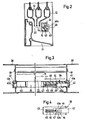
- a frame 10 for shower cubicles according to FIG. 1 has on the underside an approximately L-shaped rail 11, on the short outside leg 11a of which three movable partition walls are guided as sliding doors 12, which are slidably suspended from an upper cross member (not shown) ).
- the leg 11a is bent inward in a U-shape.
- Another, longer leg 11b serves as a water drain leg and is directed towards the shower room (damp room).
- the lower elongated L-shaped rail 11 is fixed between two side U-shaped frames 13 by means of a screw and plug connection.
- a guide bar 15 according to FIG. 1 is releasably attached to the ends of the L-shaped rail 11 as a rear guide wall on the damp side.
- the lower ends 14 of the partition walls dip into a guide slot 22 which is formed on the one hand by the leg 11a of the front guide wall and on the other hand by the movable guide bar 15.
- the guide bar 15 can be removed quickly and effortlessly in a few simple steps, so that the sliding doors 12 are also pivoted into the damp room and thus the guide surfaces of the rail 11 can be cleaned. After completion of the cleaning process, the guide bar 15 can be easily integrated again.
- the L-shaped lower rail 11 is connected to two lateral I-shaped frame parts 38 by means of screws 18; these frame parts 38 hold the guide bar 15, in which a latching device 39 is fastened at one end and a plug pin 40 is fastened at the other end, which engage in end caps 41 with recesses 41a of the frame parts 38.
- the plug pin 40 is inserted in the guide bar 15 in a clamping manner and has a nose 40a.
- the latching device 39 is fastened in the guide bar 15, the catch (latch) 42 of which also engages in the end cap 41 or the recess 41a thereof.
- the latching device consists of the latch 42, which is mounted displaceably in a plug pin 43 and is limited in its displacement by means of cams 43a which engage in the recess 44 of the latch 42.
- a plug opening 47 is arranged in the case 42 facing the interior of the cabin, in which a grip piece 48 is held in a clamping manner with a plug part 48a.
- the plug part 48a protrudes from the wall of the guide bar 15 through a slot 49 to the interior, so that the handle 48 is on the outer surface of the guide bar 15 and is therefore easy to operate while overcoming the spring force.
- peripheral frame 51 the side parts 51a of which are preferably formed from U-shaped extruded profiles and on the upper cross member 52, for example, three sliding partitions 53 (sliding doors) are suspended in corresponding slide rails and the Can give access to the wet room (shower cubicle).
- the lower cross member 54 which can rest on the edge of the shower tray, has a front guide wall 55 which runs downward and inward toward the damp room as a water drainage leg 56. Both crossbars 52, 54 are equipped with corresponding grooves 57 in order to connect the side parts 51a into a frame 51 by means of screws 58.
- the partition walls 53 slidably suspended on the upper cross member 52 each have a guide bar 59 on the underside, to which end caps 60 are attached.
- the end caps 60 of the front partition 53 can rest against the front guide wall 55 of the lower cross member 54.
- a guide rail 62 is arranged opposite the guide wall 55 of the lower cross member 54, forming a guide slot 61, which limits the guide strips 59 of the inner partition wall 53.
- the guide bar 62 which is preferably manufactured as an extruded profile, is clamped in the side parts 51a of the U-shaped frame 51.
- the guide bar ends are supported in the cross section of the guide bar 62 by correspondingly designed bushes 63 which are kept inserted in openings 64 of the side parts 51a and hold the guide bar 62 in a clamping manner against displacement.
- This guide bar 62 is preferably made of plastic and has a U-shaped cross section, the free legs 62a of which are directed towards the water leg 56 of the lower cross bar 54 (i.e. downwards).
- the elastically flexible guide bar 62 can be pressed downward in its central part.
- the partitions 53 can now be pivoted away (cf. FIGS. 6 and 8).
- the partition walls 53 are also introduced into the guide slot 61 by bending the guide rail 62 downward until the upper edge of the guide rail 62 lies below the lower edge of the guide rail 59 of the partition walls 53, so that these can then be pivoted in.
- Such a U-shaped plastic guide bar 62 has the advantage that during the bending the free legs 62a partially deform outwards in the bending area, the lateral stability of the guide bar 62 being favorably supported.
- the guide bar 62 is preferably formed by two tube ends 65, which or the like by means of a leaf spring 66. by rivets 67, screws or the like. are interconnected.
- a guide bar 62 designed in this way can be pressed downward at an obtuse angle for pivoting the partition walls 53 for cleaning purposes, the lateral stability being retained by the flat leaf spring 66.
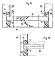
- a guide bar 68 shown in FIGS. 11 and 12 is also U-shaped and has a bent resilient tongue 69 on the underside, which is supported on the water drainage leg 56 of the cross bar 54 or on the tub rim.
- the tongue 69 is preferably formed from the same material of the guide rail 68 and is arranged approximately in the middle in accordance with its length.
- the bearing bushes 70 are rectangular in cross section and can be connected to the side parts 51 a of the frame 52 by means of the screws 58.
- the guide bar 68 is inserted by inserting one end into an opening 70a of the bearing bushes 70 of a side part 51a until the other end lies in front of the opposite opening 70a of the other bearing bushing 70 and can then be inserted.
- the guide bar 68 is held in position by the beads 71.
- the bearing bush 70 shown in FIG. 12 it has an inward and upward slope 72 in the opening 70a, the upper bead 71 resting close to the end of the guide rail.
- the bevel 72 causes the ends to slide out slightly when the guide bar is bent to remove it.
Landscapes
- Health & Medical Sciences (AREA)
- Public Health (AREA)
- Epidemiology (AREA)
- General Health & Medical Sciences (AREA)
- Support Devices For Sliding Doors (AREA)
- Domestic Plumbing Installations (AREA)
Claims (8)
Priority Applications (1)
| Application Number | Priority Date | Filing Date | Title |
|---|---|---|---|
| AT81109848T ATE23103T1 (de) | 1980-11-25 | 1981-11-24 | Duschabtrennung. |
Applications Claiming Priority (4)
| Application Number | Priority Date | Filing Date | Title |
|---|---|---|---|
| DE8031363 | 1980-11-25 | ||
| DE8031363U | 1980-11-25 | ||
| DE8120556U | 1981-07-14 | ||
| DE8120556 | 1981-07-14 |
Publications (3)
| Publication Number | Publication Date |
|---|---|
| EP0052882A2 EP0052882A2 (fr) | 1982-06-02 |
| EP0052882A3 EP0052882A3 (en) | 1982-09-01 |
| EP0052882B1 true EP0052882B1 (fr) | 1986-10-29 |
Family
ID=25948763
Family Applications (1)
| Application Number | Title | Priority Date | Filing Date |
|---|---|---|---|
| EP81109848A Expired EP0052882B1 (fr) | 1980-11-25 | 1981-11-24 | Ecran de douche |
Country Status (1)
| Country | Link |
|---|---|
| EP (1) | EP0052882B1 (fr) |
Cited By (1)
| Publication number | Priority date | Publication date | Assignee | Title |
|---|---|---|---|---|
| DE3722776A1 (de) * | 1987-07-09 | 1989-01-26 | Walter Prader | Untere fuehrung fuer eine trennwand fuer feuchtraeume |
Families Citing this family (4)
| Publication number | Priority date | Publication date | Assignee | Title |
|---|---|---|---|---|
| DE3435905A1 (de) * | 1984-09-29 | 1986-04-17 | Heinz Georg Hünibach Thun Baus | Trennwand |
| GB8600358D0 (en) * | 1986-01-08 | 1986-02-12 | Contour Doors Ltd | Shower cabinet |
| DE4106117C2 (de) * | 1991-02-27 | 1994-03-10 | Semer Gmbh & Co Kg W | Schiebetürführung, insbesondere für Duschabtrennungen und dgl. |
| CN109730562B (zh) * | 2019-02-20 | 2020-12-18 | 宣城市欧帝斯卫浴有限公司 | 一种方便使用的高强度淋浴房 |
Family Cites Families (2)
| Publication number | Priority date | Publication date | Assignee | Title |
|---|---|---|---|---|
| DE8031363U1 (de) * | 1981-10-22 | Bernhard Vorndamme Gmbh & Co, 4902 Bad Salzuflen | Duschabtrennung | |
| DE2747480C2 (de) * | 1977-10-22 | 1979-08-30 | Heinz Georg Thun Baus (Schweiz) | Untere Führung für eine Schiebetrennwand |
-
1981
- 1981-11-24 EP EP81109848A patent/EP0052882B1/fr not_active Expired
Cited By (1)
| Publication number | Priority date | Publication date | Assignee | Title |
|---|---|---|---|---|
| DE3722776A1 (de) * | 1987-07-09 | 1989-01-26 | Walter Prader | Untere fuehrung fuer eine trennwand fuer feuchtraeume |
Also Published As
| Publication number | Publication date |
|---|---|
| EP0052882A2 (fr) | 1982-06-02 |
| EP0052882A3 (en) | 1982-09-01 |
Similar Documents
| Publication | Publication Date | Title |
|---|---|---|
| EP0226785B1 (fr) | Renvoi d'angle pour tringles d'immobilisation d'une fenêtre ou porte | |
| EP0389000A1 (fr) | Cloison pour douche | |
| DE3309606A1 (de) | Trennwand | |
| WO2018033464A1 (fr) | Châssis destiné à un tiroir | |
| DE19653897B4 (de) | Führungsanordnung für ein Türelement | |
| EP0052882B1 (fr) | Ecran de douche | |
| DE10025951A1 (de) | Befestigungsanordnung | |
| DE2013231B2 (de) | Gleitschienenfuehrung | |
| DE2253600A1 (de) | Stange zum einfuehren von vorhangtraegern | |
| DE3800445C2 (de) | Führung für eine Schiebetür od. dgl., insbesondere bei Dusch- oder Badewannenabtrennungen | |
| DE2419546C3 (de) | Schrank mit herausziehbaren Schubladenelementen | |
| DE9003313U1 (de) | Befestigungs- und/oder Haltevorrichtung für Röllchenleisten auf Trägerschienen o.dgl., insbesondere von Durchlaufregalen | |
| WO2011095439A1 (fr) | Tiroir à système diviseur | |
| EP0078466A2 (fr) | Etagère avec cadre porteur et parois d'encadrement amovibles | |
| DE4106117C2 (de) | Schiebetürführung, insbesondere für Duschabtrennungen und dgl. | |
| DE3239127C2 (de) | Dusch- oder Badewannenabtrennung | |
| DE3800882A1 (de) | Trennwand, insbesondere fuer eine eck- oder runddusche | |
| DE8120556U1 (de) | "Duschabtrennung" | |
| DE2209532A1 (de) | Stange zum einfuehren von vorhangtraegern | |
| DE8031363U1 (de) | Duschabtrennung | |
| DE4330152C2 (de) | Führung für eine Schiebetrennwand | |
| DE7536307U (de) | Fensterwischer | |
| AT390994B (de) | Untere fuehrung fuer eine trennwand fuer feuchtraeume | |
| EP0253008B1 (fr) | Rail de guidage | |
| DE3722776C2 (fr) |
Legal Events
| Date | Code | Title | Description |
|---|---|---|---|
| PUAI | Public reference made under article 153(3) epc to a published international application that has entered the european phase |
Free format text: ORIGINAL CODE: 0009012 |
|
| AK | Designated contracting states |
Designated state(s): AT BE CH FR GB IT NL |
|
| PUAL | Search report despatched |
Free format text: ORIGINAL CODE: 0009013 |
|
| AK | Designated contracting states |
Designated state(s): AT BE CH FR GB IT NL |
|
| 17P | Request for examination filed |
Effective date: 19830301 |
|
| RAP1 | Party data changed (applicant data changed or rights of an application transferred) |
Owner name: META-REGALBAU GMBH & CO. KG |
|
| GRAA | (expected) grant |
Free format text: ORIGINAL CODE: 0009210 |
|
| AK | Designated contracting states |
Kind code of ref document: B1 Designated state(s): AT BE CH FR GB IT LI NL |
|
| PG25 | Lapsed in a contracting state [announced via postgrant information from national office to epo] |
Ref country code: IT Free format text: LAPSE BECAUSE OF FAILURE TO SUBMIT A TRANSLATION OF THE DESCRIPTION OR TO PAY THE FEE WITHIN THE PRESCRIBED TIME-LIMIT;WARNING: LAPSES OF ITALIAN PATENTS WITH EFFECTIVE DATE BEFORE 2007 MAY HAVE OCCURRED AT ANY TIME BEFORE 2007. THE CORRECT EFFECTIVE DATE MAY BE DIFFERENT FROM THE ONE RECORDED. Effective date: 19861029 |
|
| REF | Corresponds to: |
Ref document number: 23103 Country of ref document: AT Date of ref document: 19861115 Kind code of ref document: T |
|
| ET | Fr: translation filed | ||
| PLBE | No opposition filed within time limit |
Free format text: ORIGINAL CODE: 0009261 |
|
| STAA | Information on the status of an ep patent application or granted ep patent |
Free format text: STATUS: NO OPPOSITION FILED WITHIN TIME LIMIT |
|
| 26N | No opposition filed | ||
| REG | Reference to a national code |
Ref country code: CH Ref legal event code: PUE Owner name: DUSAR KUNSTSTOFF- UND METALLWAREN GMBH |
|
| REG | Reference to a national code |
Ref country code: GB Ref legal event code: 732E |
|
| NLS | Nl: assignments of ep-patents |
Owner name: DUSAR KUNSTSTOFF- UND METALLWAREN GMBH TE ANHAUSEN |
|
| REG | Reference to a national code |
Ref country code: FR Ref legal event code: TP |
|
| PGFP | Annual fee paid to national office [announced via postgrant information from national office to epo] |
Ref country code: GB Payment date: 20001030 Year of fee payment: 20 |
|
| PGFP | Annual fee paid to national office [announced via postgrant information from national office to epo] |
Ref country code: FR Payment date: 20001116 Year of fee payment: 20 |
|
| PGFP | Annual fee paid to national office [announced via postgrant information from national office to epo] |
Ref country code: CH Payment date: 20001122 Year of fee payment: 20 Ref country code: BE Payment date: 20001122 Year of fee payment: 20 Ref country code: AT Payment date: 20001122 Year of fee payment: 20 |
|
| PGFP | Annual fee paid to national office [announced via postgrant information from national office to epo] |
Ref country code: NL Payment date: 20001123 Year of fee payment: 20 |
|
| BE20 | Be: patent expired |
Free format text: 20011124 *DUSAR KUNSTSTOFF UND METALLWAREN G.M.B.H. |
|
| PG25 | Lapsed in a contracting state [announced via postgrant information from national office to epo] |
Ref country code: LI Free format text: LAPSE BECAUSE OF EXPIRATION OF PROTECTION Effective date: 20011123 Ref country code: GB Free format text: LAPSE BECAUSE OF EXPIRATION OF PROTECTION Effective date: 20011123 Ref country code: CH Free format text: LAPSE BECAUSE OF EXPIRATION OF PROTECTION Effective date: 20011123 |
|
| PG25 | Lapsed in a contracting state [announced via postgrant information from national office to epo] |
Ref country code: NL Free format text: LAPSE BECAUSE OF EXPIRATION OF PROTECTION Effective date: 20011124 Ref country code: AT Free format text: LAPSE BECAUSE OF EXPIRATION OF PROTECTION Effective date: 20011124 |
|
| REG | Reference to a national code |
Ref country code: CH Ref legal event code: PL |
|
| REG | Reference to a national code |
Ref country code: GB Ref legal event code: PE20 Effective date: 20011123 |
|
| NLV7 | Nl: ceased due to reaching the maximum lifetime of a patent |
Effective date: 20011124 |