EP0052926B1 - Einrichtung zum Vernichten der bakteriellen Flora - Google Patents
Einrichtung zum Vernichten der bakteriellen Flora Download PDFInfo
- Publication number
- EP0052926B1 EP0052926B1 EP81304607A EP81304607A EP0052926B1 EP 0052926 B1 EP0052926 B1 EP 0052926B1 EP 81304607 A EP81304607 A EP 81304607A EP 81304607 A EP81304607 A EP 81304607A EP 0052926 B1 EP0052926 B1 EP 0052926B1
- Authority
- EP
- European Patent Office
- Prior art keywords
- housing
- temperature
- heating means
- predetermined
- heating
- Prior art date
- Legal status (The legal status is an assumption and is not a legal conclusion. Google has not performed a legal analysis and makes no representation as to the accuracy of the status listed.)
- Expired
Links
Images

Classifications
-
- E—FIXED CONSTRUCTIONS
- E03—WATER SUPPLY; SEWERAGE
- E03C—DOMESTIC PLUMBING INSTALLATIONS FOR FRESH WATER OR WASTE WATER; SINKS
- E03C1/00—Domestic plumbing installations for fresh water or waste water; Sinks
- E03C1/12—Plumbing installations for waste water; Basins or fountains connected thereto; Sinks
- E03C1/126—Installations for disinfecting or deodorising waste-water plumbing installations
-
- A—HUMAN NECESSITIES
- A61—MEDICAL OR VETERINARY SCIENCE; HYGIENE
- A61L—METHODS OR APPARATUS FOR STERILISING MATERIALS OR OBJECTS IN GENERAL; DISINFECTION, STERILISATION OR DEODORISATION OF AIR; CHEMICAL ASPECTS OF BANDAGES, DRESSINGS, ABSORBENT PADS OR SURGICAL ARTICLES; MATERIALS FOR BANDAGES, DRESSINGS, ABSORBENT PADS OR SURGICAL ARTICLES
- A61L11/00—Methods specially adapted for refuse
-
- A—HUMAN NECESSITIES
- A61—MEDICAL OR VETERINARY SCIENCE; HYGIENE
- A61L—METHODS OR APPARATUS FOR STERILISING MATERIALS OR OBJECTS IN GENERAL; DISINFECTION, STERILISATION OR DEODORISATION OF AIR; CHEMICAL ASPECTS OF BANDAGES, DRESSINGS, ABSORBENT PADS OR SURGICAL ARTICLES; MATERIALS FOR BANDAGES, DRESSINGS, ABSORBENT PADS OR SURGICAL ARTICLES
- A61L2/00—Disinfection or sterilisation of materials or objects, in general; Accessories therefor
- A61L2/02—Disinfection or sterilisation of materials or objects, in general; Accessories therefor using physical processes
- A61L2/04—Heat
-
- A—HUMAN NECESSITIES
- A61—MEDICAL OR VETERINARY SCIENCE; HYGIENE
- A61L—METHODS OR APPARATUS FOR STERILISING MATERIALS OR OBJECTS IN GENERAL; DISINFECTION, STERILISATION OR DEODORISATION OF AIR; CHEMICAL ASPECTS OF BANDAGES, DRESSINGS, ABSORBENT PADS OR SURGICAL ARTICLES; MATERIALS FOR BANDAGES, DRESSINGS, ABSORBENT PADS OR SURGICAL ARTICLES
- A61L2/00—Disinfection or sterilisation of materials or objects, in general; Accessories therefor
- A61L2/24—Apparatus using programmed or automatic operation
-
- C—CHEMISTRY; METALLURGY
- C02—TREATMENT OF WATER, WASTE WATER, SEWAGE, OR SLUDGE
- C02F—TREATMENT OF WATER, WASTE WATER, SEWAGE, OR SLUDGE
- C02F1/00—Treatment of water, waste water, or sewage
- C02F1/02—Treatment of water, waste water, or sewage by heating
-
- Y—GENERAL TAGGING OF NEW TECHNOLOGICAL DEVELOPMENTS; GENERAL TAGGING OF CROSS-SECTIONAL TECHNOLOGIES SPANNING OVER SEVERAL SECTIONS OF THE IPC; TECHNICAL SUBJECTS COVERED BY FORMER USPC CROSS-REFERENCE ART COLLECTIONS [XRACs] AND DIGESTS
- Y02—TECHNOLOGIES OR APPLICATIONS FOR MITIGATION OR ADAPTATION AGAINST CLIMATE CHANGE
- Y02A—TECHNOLOGIES FOR ADAPTATION TO CLIMATE CHANGE
- Y02A20/00—Water conservation; Efficient water supply; Efficient water use
- Y02A20/20—Controlling water pollution; Waste water treatment
Definitions
- This invention relates to a device for destroying bacterial flora by the sterilization of contaminated waste which contains the bacterial flora.
- waste materials are often disposed of by pouring the material down sinks and the like. This waste material may therefore gather in the S-bends or the like, of drainage pipes where bacterial flora in the waste material flourishes.
- the bacterial flora which builds up on the drainage pipe is extremely dangerous, particularly in hospitals where it is possible that sterile equipment may be contaminated by the bacterial flora. Indeed, it has been known for a patient in a hospital to contract a sickness which has been attributed to bacterial flora contamination of instruments which has been used in connection with the patient.
- the present invention concerns an improvement to the device disclosed in European Patent Application No. 80301799.5 (Publication No. 20157) and invented by the inventor of the present application.
- European Patent Application No. 80301799.5 Publication No. 20157
- a device for destroying bacterial flora by sterilization of contaminated waste which contains the bacterial flora, comprising a housing having an inlet to allow waste material to pass into said housing and heating means in said housing for heating the waste material such that any bacterial flora which gathers in or on the housing may be sterilized by heat from said heating means.
- An object of the present invention is to provide such a device with means for controlling the heating means to maintain the temperature of the waste material in the housing above a predetermined value, so that the material does not completely cool between sterilizing steps, and also to prevent the waste material from being heated to too high a temperature.
- the invention includes a device for destroying bacterial flora by sterilization of contaminated waste which contains the bacterial flora, comprising a housing, said housing having an inlet to allow waste material to pass into said housing, and heating means in said housing for heating the waste material such that any bacterial flora which gathers in or on said housing may be sterilized by heat from said heating means, to thereby destroy said bacterial flora
- said device further includes means for controlling said heating means to maintain the temperature in said housing above a first predetermined value said means including sensing means for sensing the temperature of water in the housing and energizing the heater means when the temperature drops below the predetermined value, and second sensing means to determine if the temperature in the housing exceeds a second predetermined value and to cause the heating means to be de-energized if the temperature exceeds the second predetermined value.
- the invention also includes a device for destroying bacterial flora by sterilization of contaminated waste which contains the bacterial flora, said device comprising a housing, said housing having an inlet to allow waste material to pass into said housing, and heating means in said housing for heating the waste material such that any bacterial flora which gathers in or on said housing may be sterilized by heat from said heating means, wherein said device further comprises a liquid temperature sensor for sensing the temperature of liquid within the housing, a housing temperature sensor for sensing the temperature of the housing, a probe mounted in the housing for sensing the level of liquid within the housing so as to change states if the level falls below a predetermined level, and temperature controlling means electrically connected to the liquid temperature sensor, the housing temperature sensor, the probe and the heating means, said temperature controlling means being arranged to energize the heating means for a predetermined time period if the sensed liquid temperature is below a first predetermined temperature value and if the liquid level is above its predetermined level; provided that, the housing temperature remains less than a second pre
- the device is formed as a waste trap and comprises an elongate housing including means for connection to a drainage pipe, and heating means.
- the present invention includes a waste trap device for destroying bacterial flora by sterilization of contaminated liquid waste which contains the bacterial flora, said device comprising an elongate housing including means for connection to a drainage pipe, and heating means wherein the longitudinal axis of the housing is transverse to that of the drainage pipe so as to form at least part of water plug and, thereby facilitate connection and maintenance of the device, the heating means being for heating the waste material such that any bacterial flora which gathers in or on said housing may be sterilized by heat from said heating means, means for controlling the heating means so as to maintain the temperature in the liquid waste above a first predetermined value, said temperature controlling means further comprising means for sensing the temperature in the housing, said temperature sensing means being located in a lower portion of said housing, and a low level probe mounted through an upper portion of the housing so as to project into said housing the probe interfaced with said heating means for sensing when liquid in the housing drops below a predetermined level and for causing the heating means to be de-energized when the
- the device 100 embodying the invention is shown located in a water plug section 150 of a drainage pipe for example an S-bend.
- the device 100 includes a housing 120 having an inlet pipe 122 and an outlet pipe 124 both of which form part of the S-bend.
- the inlet and outlet pipes 122 and 124 are preferably provided with coupling flanges (not shown) and heat resistant gaskets which allow the pipes 122 and 124 to be connected to the remainder of the drainage pipe (not shown).
- the housing 120 has one end provided with a removable plug 126 and a heat resistant gasket 128 which allows the interior of the housing to be inspected for purposes of maintenance and the like.
- the other end is permanently closed by a member 130 which has two openings, the purpose of which will be evident from the following.
- a first opening 140 receiving a closed sleeve 132 for housing an IC temperature sensor (not shown).
- the sleeve 132 is screwed into opening 140 by co-operating screw threads on the sleeve and opening.
- the second opening 142 receives a screw threaded plug 144 which carries a heating element 160 and a temperature sensor probe pocket 162 and the plug 144 is screwed into opening 142 to close that opening.
- the pocket 162 carries a sensor probe 164 for measuring the temperature in the interior of the housing 120.
- the probe 164 is preferably a bellows type heat sensor preferably made by TL.L. Thermatic Controls Ltd. Canada, No. 53438.
- the housing 120 also has a liquid level detecting probe 170 projecting thereinto.
- the probe 170 is preferably a "low level probe” made and sold by L. W. Gemmell, 72 Silverside Road, Eaglemont Victoria 3084, Australia and the heating element 160 is made and sold by Stokes Australia Ltd., Sullon Street, Brunswick, Victoria, Australia.
- the probe 170 is located in housing 172 provided on the top of the housing 120 and the probe monitors the liquid level in the housing. If the liquid level falls below the level of the probe the operation of the unit will be stopped as will be described hereinbelow. Should the probe 170 fail, the probe 164, as will be described hereinbelow, also cuts off operation of the device and the device will not operate again until manual reset button 180 is depressed, to close manual reset switch SW1.
- a compartment 200 is located at one end of the housing 120 and the IC temperature sensor in sleeve 132, heating element 160 and probe 162 communicate with the compartment. Also the probe 170 communicates with the compartment 200 by cable 173.
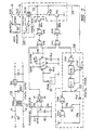
- the compartment 200 housing the circuitry and timer etc. for operating the device which will be described with reference to figure 2.
- a conventional 240V power supply is stepped down to 12V by a transformer 222.
- the stepped down 12V supply is regulated by a voltage regulator, IC1, which is a 12VDC voltage regulator No. 7812 made by Fair- child, and smoothed by filter capacitors as shown.
- the 12V supply is converted to DC by a rectified diode (not shown) and is used to power the logic circuit to be described thereinafter.
- a 5 amp fuse 111 is provided in the 240V power supply as shown.
- the 240V supply is also connected with heating element 160 through switches RL1/2 and RL1/3 to power the heating element 160.
- a neon indicator lamp 224 is provided in parallel with the heating element to indicate that power is being supplied to the heating element 160.
- the heating element is controlled by the IC temperature sensor IC2 which is located in sleeve 132.
- the sensor IC2 is preferably a temperature sensor no. AD 590JH made by Analog Devices.
- the sensor IC2 produces a constant current output proportional to the temperature of the liquid in housing 120, which current is fed to ground via a resistor as shown to develop a voltage proportional to temperature. This voltage is compared with a preset voltage of 3.08V across variable resistor R1 which is equal to a temperature of 35°C.
- An operation amplifier IC3 (no. 741C made by National Semiconductors) with open loop gain is used to compare the sensor and the voltage across resistor R1 and produce a high output when the temperature is below 35°C.
- the output of the operational amplifier is applied to one input of a two input NAND gate IC4A.
- the other input to NAND gate IC4A comes from probe 170 which will be described in detail hereinafter.
- gate IC4A is fed to a similar gate IC4B and then through a resistor to a switching transistor TR1.
- the switching transistor is connected to a relay which closes switches RL1/1, RL1/2 and RL1/3 when power is supplied to the relay. Accordingly if the sensor IC2 senses a temperature below 35°C the output of the operational amplifier IC3 is high.
- the output from probe 170 is high if the water level in housing 120 is in the safe level condition i.e. above a certain level so that gate IC4A is supplied with two high inputs and therefore supplies a low input to gate IC4B which applies a high signal to transistor TR1 to turn the transistor on.
- the switch RL1/1 ensures that relay RL1/3 remains latched to continue supply power to the heating element.
- the probe 170 ensures that heating element 160 is not powered if the water level in housing 120 is below a predetermined level i.e. below the probe 170, wherein the heating element may burn out or be otherwise damaged due to lack of water in the housing 120.
- the output from the probe 170 and Fluid Detector IC5 which is preferably a Fluid Detector LM 1830 made by National Semiconductors is high thereby operating gate IC4A as described above. If the liquid level is lower than the predetermined level established by probe 170 the output from sensor IC5 is low and accordingly the output from gate IC4A is high the output from gate IC4B is low and transistor TR1 is not switched on. Therefore relay RL1/3 does not close switches RL1/1 to RL1/3 and power is not supplied to heating element 160. Power will not be supplied to heating element 160 until the liquid level is above the probe 170 and the temperature sensor IC2 senses a temperature below 35°C.
- the probe 170 and temperature sensor IC5 will also stop supplying power to the heating element 160 if during a heating cycle the liquid drops below probe 170, which may occur if many heating cycles have occurred and no water has passed into the housing 120.
- the output of sensor IC5 is applied to an input of a two input NAND gate IC4C.
- the other input to IC4C is from digital timer 250 which will be described hereinafter.
- gate IC4C will apply a low output to gate IC4D which will apply a high signal to transistor TR2 to turn the transistor on. It will therefore be seen that relay RL1/3 is powered by the circuit label 260.
- the NAND gates IC4A to C are preferably made by National Semiconductor under no. 4011 C.
- the time the heating element 160 is powered to heat the liquid in the housing 120 is desirably about 17 minutes. This time is controlled by digital timer 250 which comprises an oscillator 250 which includes NAND gates IC6A and IC6B and which is continually in operation, counter IC7 and IC8 and NAND IC6C.
- the period of oscillation of the oscillator 252 is set by variable resistor R2 and applies a pulse to counter IC7 once every two seconds.
- the counter IC7 is a seven stage counter and supplies a pulse from pin 3 to IC8 for every 128 pulses received from the oscillator 252.
- the counter IC8 is the same as the counter IC7 but applies a pulse from its pin 4 for every 32 pulses received.
- the output from counter IC8 is applied to gate IC6C which applies a lower output to NAND gate IC4C after every 4,096 oscillations of oscillator 252. Accordingly a high output is applied to gate IC4D and a low output is applied to transistor TR2 to turn the transistor off thereby disrupting power supply to relay RL1/3 to cut off power supply to the heating element 160.
- the counters IC7 and IC8 are reset and commence counting on receiving of signals on line 270.
- point 272 experiences a high voltage which when applied to pin 2 of the counters IC7 and IC8 prevents the counters from counting.
- the relay is powered to in turn close switches RL1/1 to RL1/3 the point 272 experiences low voltage which is applied to pin 2 of counters IC7 and IC8 and this results in the counters resetting to zero and allows the counters to commence counting, until the counter IC3 applies its high signal gate IC6C which as noted above cuts off the power to heating element 160 to end a heating cycle.
- the counters IC7 and IC8 are seven stage counters no. 4024 made by Texas Instruments and the gates IC6A and IC6C are Quad 2 input NAND gates no. 4011C made by National Semiconductors.
- a over temperature cut out switch SW1 is provided which is connected to bellows type probe 184. If the temperature in housing 120 reaches 120°C the probe 164 expands and opens the switch SW1 to deactivate relay RL1/3 and cut off power to the heating element 160. The switch SW1 must be manually closed to allow the relay to be reactivated. Accordingly if for some reason the probe 170 etc should fail and not cut off power to the heating element 160 the probe 164 will sense that the heating element 160 is over heating and disrupt power to the heating element.
- the device will automatically heat the contents of the housing 120 for a period of 17 minutes and will automatically shut off power to the heating element after that time has elapsed and again activate the heating element if the temperature in the housing drops below 35°C. Also if the liquid level drops below a certain level or the temperature in the housing rises above a certain level power to the heating element will be disrupted thereby prevent damage to the heating element 160 or to the device itself.
- the heating element 160 When actuated the heating element 160 which is in contact with water and waste material in the S bend of a drainage pipe in which the device accordingly to the present embodiment is located, boils the water and waste material which forms the water plug in the S bend and which is located in the housing 160 to destroy bacteria therein.
- the boiling action is the cylinder causes boiling water to bubble through the S bend 150 and heat from the boiling water is circulated throughout the inlet and outlet pipe to the S bend to destroy any bacteria which may adhere to the surfaces of these members. Any bacteria which of course passes out of the S bend is not a problem since it is not capable of contaminating sterile equipment.
- Heat resistant washers may also be provided for coupling the device 100 in a pipe to prevent heat conductions beyond the heat resistant washers.
- Steam trap (not shown) may also be provided at the top of the pipe between a sink or the like and the device 100 to prevent steam from escaping from the pipe.
Landscapes
- Health & Medical Sciences (AREA)
- Life Sciences & Earth Sciences (AREA)
- Public Health (AREA)
- Epidemiology (AREA)
- Animal Behavior & Ethology (AREA)
- General Health & Medical Sciences (AREA)
- Veterinary Medicine (AREA)
- Engineering & Computer Science (AREA)
- Environmental & Geological Engineering (AREA)
- Hydrology & Water Resources (AREA)
- Water Supply & Treatment (AREA)
- Chemical & Material Sciences (AREA)
- Organic Chemistry (AREA)
- Apparatus For Disinfection Or Sterilisation (AREA)
- Cosmetics (AREA)
- Heat Treatment Of Water, Waste Water Or Sewage (AREA)
Claims (28)
Priority Applications (1)
| Application Number | Priority Date | Filing Date | Title |
|---|---|---|---|
| AT81304607T ATE12893T1 (de) | 1980-11-21 | 1981-10-05 | Einrichtung zum vernichten der bakteriellen flora. |
Applications Claiming Priority (2)
| Application Number | Priority Date | Filing Date | Title |
|---|---|---|---|
| AU6584/80 | 1980-11-21 | ||
| AUPE658480 | 1980-11-21 |
Publications (3)
| Publication Number | Publication Date |
|---|---|
| EP0052926A2 EP0052926A2 (de) | 1982-06-02 |
| EP0052926A3 EP0052926A3 (en) | 1982-12-15 |
| EP0052926B1 true EP0052926B1 (de) | 1985-04-24 |
Family
ID=3768837
Family Applications (1)
| Application Number | Title | Priority Date | Filing Date |
|---|---|---|---|
| EP81304607A Expired EP0052926B1 (de) | 1980-11-21 | 1981-10-05 | Einrichtung zum Vernichten der bakteriellen Flora |
Country Status (5)
| Country | Link |
|---|---|
| EP (1) | EP0052926B1 (de) |
| JP (1) | JPS57107161A (de) |
| AT (1) | ATE12893T1 (de) |
| DE (1) | DE3170155D1 (de) |
| NZ (1) | NZ197768A (de) |
Families Citing this family (3)
| Publication number | Priority date | Publication date | Assignee | Title |
|---|---|---|---|---|
| JPH0677740U (ja) * | 1993-04-17 | 1994-11-01 | 邦夫 宮明 | 温度管理機能付消毒器 |
| FR2812815B1 (fr) * | 2000-08-08 | 2002-11-08 | Jean Jacques Boiffier | Procede et dispositif de traitement sanitaire simultane d'un fluide et de son reseau |
| EP1520592A1 (de) * | 2003-09-30 | 2005-04-06 | Tecno Service First S.r.l. | Vorrichtung zur Behandlung von Krankenhausabfällen |
Family Cites Families (5)
| Publication number | Priority date | Publication date | Assignee | Title |
|---|---|---|---|---|
| US2708074A (en) * | 1952-12-03 | 1955-05-10 | Hospital Sanitation Equipment | Process for disposal of contaminated hospital waste |
| JPS4919671B1 (de) * | 1970-09-07 | 1974-05-18 | ||
| JPS4919671A (de) * | 1972-06-29 | 1974-02-21 | ||
| DE2503605A1 (de) * | 1975-01-29 | 1976-08-05 | Georg Kinzler | Thermische desinfektion von abwaessern |
| AU528904B2 (en) * | 1979-06-01 | 1983-05-19 | Craig Gemmell | Heat sterilizing device |
-
1981
- 1981-07-20 NZ NZ197768A patent/NZ197768A/en unknown
- 1981-10-05 AT AT81304607T patent/ATE12893T1/de active
- 1981-10-05 DE DE8181304607T patent/DE3170155D1/de not_active Expired
- 1981-10-05 EP EP81304607A patent/EP0052926B1/de not_active Expired
- 1981-11-05 JP JP56176577A patent/JPS57107161A/ja active Pending
Also Published As
| Publication number | Publication date |
|---|---|
| JPS57107161A (en) | 1982-07-03 |
| DE3170155D1 (en) | 1985-05-30 |
| EP0052926A3 (en) | 1982-12-15 |
| NZ197768A (en) | 1988-04-29 |
| ATE12893T1 (de) | 1985-05-15 |
| EP0052926A2 (de) | 1982-06-02 |
Similar Documents
| Publication | Publication Date | Title |
|---|---|---|
| US4733798A (en) | Method and apparatus for controlling the concentration of a chemical solution | |
| US5587055A (en) | Water distilling apparatus and method | |
| US4502164A (en) | Device for destroying bacterial flora | |
| US4942868A (en) | Ultrasonic treatment of animals | |
| DE69629499T2 (de) | Vorrichtung und verfahren zur leckaufspürung in medizinischen abdecktüchern | |
| DE69938245T2 (de) | Steuerungssystem für bädern | |
| US4809915A (en) | Waste disposal apparatus | |
| US20120328484A1 (en) | Biowaste sterilizer | |
| US5407641A (en) | Microwave apparatus, and container for use in a microwave apparatus | |
| US5427737A (en) | Process and system for biologically neutralizing waste material | |
| US6666966B1 (en) | Self-disinfecting drain trap in drainage channels | |
| EP0423102A1 (de) | Apparat und Verfahren zur Kontrolle eines Stromregelventils in Abhängigkeit von der Annäherung eines menschlichen Körperteils | |
| GB2235877A (en) | Closed wound suction apparatus | |
| US5246674A (en) | Microwave apparatus, and container for use in a microwave apparatus | |
| US5308000A (en) | Water saver control for disposers | |
| EP0052926B1 (de) | Einrichtung zum Vernichten der bakteriellen Flora | |
| US20050045621A1 (en) | Bathing unit control system with capacitive water level sensor | |
| CA2089759A1 (en) | Hydro impact medical and dental instruments washer | |
| FR2792414B1 (fr) | Procede et dispositif de controle in situ d'une cuve contenant une huile ou graisse de friture | |
| NZ211876A (en) | Sterilisation of sink drain waste: heating of waste for predetermined period | |
| US5730944A (en) | Forced water fill and drainage for an unplumbed sterilizer | |
| EP0020157B1 (de) | Vorrichtung zum Vernichten der bakteriellen Flora | |
| KR200211674Y1 (ko) | 사우나부스용 증기 발생장치 | |
| RU2147101C1 (ru) | Электропароводонагреватель | |
| SU1599697A1 (ru) | Устройство дл стерильного отбора проб жидкости |
Legal Events
| Date | Code | Title | Description |
|---|---|---|---|
| PUAI | Public reference made under article 153(3) epc to a published international application that has entered the european phase |
Free format text: ORIGINAL CODE: 0009012 |
|
| AK | Designated contracting states |
Designated state(s): AT BE CH DE FR GB IT LU NL SE |
|
| PUAL | Search report despatched |
Free format text: ORIGINAL CODE: 0009013 |
|
| AK | Designated contracting states |
Designated state(s): AT BE CH DE FR GB IT LI LU NL SE |
|
| 17P | Request for examination filed |
Effective date: 19830513 |
|
| GRAA | (expected) grant |
Free format text: ORIGINAL CODE: 0009210 |
|
| AK | Designated contracting states |
Designated state(s): AT BE CH DE FR GB IT LI LU NL SE |
|
| PG25 | Lapsed in a contracting state [announced via postgrant information from national office to epo] |
Ref country code: NL Effective date: 19850424 Ref country code: IT Free format text: LAPSE BECAUSE OF FAILURE TO SUBMIT A TRANSLATION OF THE DESCRIPTION OR TO PAY THE FEE WITHIN THE PRESCRIBED TIME-LIMIT;WARNING: LAPSES OF ITALIAN PATENTS WITH EFFECTIVE DATE BEFORE 2007 MAY HAVE OCCURRED AT ANY TIME BEFORE 2007. THE CORRECT EFFECTIVE DATE MAY BE DIFFERENT FROM THE ONE RECORDED. Effective date: 19850424 Ref country code: AT Effective date: 19850424 |
|
| REF | Corresponds to: |
Ref document number: 12893 Country of ref document: AT Date of ref document: 19850515 Kind code of ref document: T |
|
| PG25 | Lapsed in a contracting state [announced via postgrant information from national office to epo] |
Ref country code: SE Effective date: 19850430 |
|
| REF | Corresponds to: |
Ref document number: 3170155 Country of ref document: DE Date of ref document: 19850530 |
|
| ET | Fr: translation filed | ||
| NLV1 | Nl: lapsed or annulled due to failure to fulfill the requirements of art. 29p and 29m of the patents act | ||
| PG25 | Lapsed in a contracting state [announced via postgrant information from national office to epo] |
Ref country code: LU Free format text: LAPSE BECAUSE OF NON-PAYMENT OF DUE FEES Effective date: 19851031 |
|
| PLBE | No opposition filed within time limit |
Free format text: ORIGINAL CODE: 0009261 |
|
| STAA | Information on the status of an ep patent application or granted ep patent |
Free format text: STATUS: NO OPPOSITION FILED WITHIN TIME LIMIT |
|
| 26N | No opposition filed | ||
| PGFP | Annual fee paid to national office [announced via postgrant information from national office to epo] |
Ref country code: GB Payment date: 19940927 Year of fee payment: 14 |
|
| PGFP | Annual fee paid to national office [announced via postgrant information from national office to epo] |
Ref country code: DE Payment date: 19941010 Year of fee payment: 14 |
|
| PGFP | Annual fee paid to national office [announced via postgrant information from national office to epo] |
Ref country code: FR Payment date: 19941011 Year of fee payment: 14 |
|
| PGFP | Annual fee paid to national office [announced via postgrant information from national office to epo] |
Ref country code: CH Payment date: 19941014 Year of fee payment: 14 |
|
| PGFP | Annual fee paid to national office [announced via postgrant information from national office to epo] |
Ref country code: BE Payment date: 19941208 Year of fee payment: 14 |
|
| PG25 | Lapsed in a contracting state [announced via postgrant information from national office to epo] |
Ref country code: GB Effective date: 19951005 |
|
| PG25 | Lapsed in a contracting state [announced via postgrant information from national office to epo] |
Ref country code: LI Effective date: 19951031 Ref country code: CH Effective date: 19951031 Ref country code: BE Effective date: 19951031 |
|
| BERE | Be: lapsed |
Owner name: GEMMELL LESLIE WALLACE Effective date: 19951031 |
|
| GBPC | Gb: european patent ceased through non-payment of renewal fee |
Effective date: 19951005 |
|
| REG | Reference to a national code |
Ref country code: CH Ref legal event code: PL |
|
| PG25 | Lapsed in a contracting state [announced via postgrant information from national office to epo] |
Ref country code: FR Effective date: 19960628 |
|
| PG25 | Lapsed in a contracting state [announced via postgrant information from national office to epo] |
Ref country code: DE Effective date: 19960702 |
|
| REG | Reference to a national code |
Ref country code: FR Ref legal event code: ST |