EP0052934A2 - Gasbrenner mit Funkenzündung - Google Patents
Gasbrenner mit Funkenzündung Download PDFInfo
- Publication number
- EP0052934A2 EP0052934A2 EP81304774A EP81304774A EP0052934A2 EP 0052934 A2 EP0052934 A2 EP 0052934A2 EP 81304774 A EP81304774 A EP 81304774A EP 81304774 A EP81304774 A EP 81304774A EP 0052934 A2 EP0052934 A2 EP 0052934A2
- Authority
- EP
- European Patent Office
- Prior art keywords
- burner
- spark
- gas
- gas burner
- ports
- Prior art date
- Legal status (The legal status is an assumption and is not a legal conclusion. Google has not performed a legal analysis and makes no representation as to the accuracy of the status listed.)
- Withdrawn
Links
Images

Classifications
-
- F—MECHANICAL ENGINEERING; LIGHTING; HEATING; WEAPONS; BLASTING
- F23—COMBUSTION APPARATUS; COMBUSTION PROCESSES
- F23D—BURNERS
- F23D14/00—Burners for combustion of a gas, e.g. of a gas stored under pressure as a liquid
- F23D14/02—Premix gas burners, i.e. in which gaseous fuel is mixed with combustion air upstream of the combustion zone
- F23D14/04—Premix gas burners, i.e. in which gaseous fuel is mixed with combustion air upstream of the combustion zone induction type, e.g. Bunsen burner
- F23D14/06—Premix gas burners, i.e. in which gaseous fuel is mixed with combustion air upstream of the combustion zone induction type, e.g. Bunsen burner with radial outlets at the burner head
- F23D14/065—Premix gas burners, i.e. in which gaseous fuel is mixed with combustion air upstream of the combustion zone induction type, e.g. Bunsen burner with radial outlets at the burner head with injector axis inclined to the burner head axis
-
- F—MECHANICAL ENGINEERING; LIGHTING; HEATING; WEAPONS; BLASTING
- F24—HEATING; RANGES; VENTILATING
- F24C—DOMESTIC STOVES OR RANGES ; DETAILS OF DOMESTIC STOVES OR RANGES, OF GENERAL APPLICATION
- F24C3/00—Stoves or ranges for gaseous fuels
- F24C3/10—Arrangement or mounting of ignition devices
- F24C3/103—Arrangement or mounting of ignition devices of electric ignition devices
Definitions
- the invention relates to a gas burner particularly, but not exclusively, for a gas cooker with spark ignition.
- Spark ignition by means of an in situ spark unit is a very desirable method of lighting gas burners, but the ratio of gas to air in the primary mixture normally supplied to a gas burner is controlled according to stoichiometric considerations in the interest of" efficiency of combustion, and. such a mixture is too gas-rich for ready ignition by an electric spark.
- a gas burner head comprising a burner body made at least substantially, and preferably of between 75% and 98%, of alumina.
- the head also comprises at least one pair of electrodes spaced apart by the body and providing a spark gap therebetween.
- One of said electrodes may be covered with a cap of ceramic glass so that a user of the burner may be protected from electric shock.
- a spark ignition gas burner comprising a burner head body of electrically insulating material formed with a plurality of passageways for the passage of combustible air-gas mixture therethrough and each terminating in a flame port, and first and second electrode means connected or connectible to spark generating means and positioned relative to said body whereby in use of the burner a spark may be produced in the vicinity of one or other of said ports.
- the burner head body may comprise a ring of ceramic material such as alumina defining, at least in part, a wall of a chamber connectible to a source of gas and air, said passageways comprise vertically elongate slots opening at the upper surface of the body and extending radially from the interior of the chamber to said ports.
- the body is supported on the first electrode means and is surmounted by the second electrode means whereby a spark may pass between the electrode means.
- the burner may further comprise a feed pipe for feeding air-gas mixture from said source to said chamber and having a restricting throat at which the cross-sectional area is less than, and preferably only between 35% to 45% of, the sum of the cross-sectional areas of the said ports.
- the burner comprises a feed pipe 1 and a burner head 2, the pipe 1 being adapted for connection to a source of gas at elevated pressure and being provided with air inlets 3 whereby air can be introduced into the pipe to provide a primary mixture of air and gas.
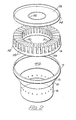
- the burner head comprises a chamber 4 of which the upper portion is defined in part by lower electrode 5.
- the electrode comprises a lower cylindrical wall 6, an upper low peripheral rim 7 and an intermediate conical portion 8.
- the lower electrode 5 supports a burner head body 9 of annular construction which is provided with a plurality, in this embodiment, forty, slots 10 which extend radially from the inside of the annulus to flame ports 19 at the outer edge thereof and downwardly from the upper surface 11.
- the radially outer surface 12 of the burner head body and the rim 7 of the lower electrode taper slightly inwardly and upwardly so tht the body may be a captive fit within the rim 7 and the lower surface of the body is angled to correspond with the conical portion 8 so that the body may be supported by the electrode as shown in Fig. 1.
- Upper electrode 13 is essentially a disc pressed out of sheet material and having a peripheral rim 14.
- the upper electrode also has an annular depression 16 corresponding in diameter to the inside diameter of the burner head body 9 so that when assembled as shown in Fig. 1 the depression 16 located against the radially inner surface of the body.
- the body 9 is made of a material which comprises between 80% and 94% of alumina, though the proportion may range from about 75% to 98%. Although this material is generally known to have poor resistance to thermal shock it is surprisingly found that at least in the construction described it is capable of withstanding very severe shock and it is thought that this may be due to the radial slots allowing for expansion and contraction without excessive build-up of strains within the alumina body.
- the assembly is surmounted by a cap 17 of ceramic glass such as CERAN or ALPHASTAE (Trade Marks) or other suitable material to protect the upper electrode from contamination and to provide electrical insulation for the safety of a user of the cooker.
- the cap is formed with a flange 18 which engages the flange 14 of the upper electrode.
- Each of the electrodes is formed of electrically conducting material such as sheet metal, and the lower electrode 5 is in electrical contact with the burner feed pipe 1 through which it may be connected electrically to the cooker or other appliance with which it is adapted to be used.
- the upper electrode is threaded on to a stem 20 (not shown in Fig. 2) which is mounted in a block 21 of insulating material which in turn is secured by sleeve 22 and nut 15 in a depression la in the lower face of the feed pipe 1.
- the stem 20 terminates in terminal 23 which is connectible to a spark generating device of any suitable type.
- Suitable types of spark generating devices include 1- shot or single-spark, continuous spark, and re-ignition types each of which may be supplied from electrical mains or battery and some of which may be alternatively powered by piezo-electrical means.
- the spark generator. is connected between terminal 23 and the feed pipe 1 of the burner, and thus the electrical potential of the generator exists between the upper electrode 13 and the lower electrode 5.
- a spark may pass between the electrode at any position around the burner but in practice it has been found that sparks normally pass down the outer face 12 of the body 9 intermediate an adjacent pair of ports 19 where the combination of primary mixture and secondary air provide an optimum ignitable mixture. Successive sparks may be located in the vicinity of the same pair of slots but it is more likely that successive sparks will be found adjacent different pairs. Contamination of surface 12 presents no problem and indeed tends to produce an even better spark, but should distortion of an electrode reduce the chance of a spark adjacent one port there are, in this embodiment, a further 39 ports near which a spark can pass. In other embodiments a fewer or even more slots may be provided around the circumference of the burner head body.
- a slight gap 24 is provided between the underside of electrode 13 and the upper face of body 9 so that the path length for leakage over a wet surface is increased by the depth d of the gap 24.
- the slots are open at the top it is a relatively easy matter to clean the slots of any contaminants, and for this purpose the assembly of upper and lower electrodes and the burner head body can be removed readily from the burner.
- the slots may be cleaned by brushing.
- the supply pipe 1 is provided with a venturi throat 26 of which the internal cross-section is between 35% and 45% and preferably of the total cross-section area of all the flame ports.
- the throat also ensures optimum conditions for aeration when high primary air is called for such as in the use of liquified petroleum gas.
Landscapes
- Engineering & Computer Science (AREA)
- Chemical & Material Sciences (AREA)
- Combustion & Propulsion (AREA)
- Mechanical Engineering (AREA)
- General Engineering & Computer Science (AREA)
- Gas Burners (AREA)
Applications Claiming Priority (4)
| Application Number | Priority Date | Filing Date | Title |
|---|---|---|---|
| GB8033111 | 1980-10-14 | ||
| GB8033111 | 1980-10-14 | ||
| GB8129250A GB2085576A (en) | 1980-10-14 | 1981-09-28 | Spark ignition gas burner |
| GB8129250 | 1981-09-28 |
Publications (2)
| Publication Number | Publication Date |
|---|---|
| EP0052934A2 true EP0052934A2 (de) | 1982-06-02 |
| EP0052934A3 EP0052934A3 (de) | 1982-08-11 |
Family
ID=26277210
Family Applications (1)
| Application Number | Title | Priority Date | Filing Date |
|---|---|---|---|
| EP81304774A Withdrawn EP0052934A3 (de) | 1980-10-14 | 1981-10-14 | Gasbrenner mit Funkenzündung |
Country Status (2)
| Country | Link |
|---|---|
| EP (1) | EP0052934A3 (de) |
| GB (1) | GB2085576A (de) |
Cited By (6)
| Publication number | Priority date | Publication date | Assignee | Title |
|---|---|---|---|---|
| FR2594213A1 (fr) * | 1986-02-13 | 1987-08-14 | Madec Mater France | Bruleur perfectionne pour combustibles gazeux a systemes d'allumage et de securite incorpores |
| FR2618881A2 (fr) * | 1986-02-13 | 1989-02-03 | Madec Mater France | Bruleur perfectionne pour combustibles gazeux a systemes d'allumage et de securite incorpores |
| FR2830075A1 (fr) * | 2001-09-27 | 2003-03-28 | Sourdillon Sa | Bruleur a gaz pour appareil de cuisson |
| ES2188332A1 (es) * | 2000-09-22 | 2003-06-16 | Bsh Fabricacion Sa | Sistema de fijacion del cuerpo encendedor en encimeras de gas. |
| WO2003091627A1 (de) | 2002-04-26 | 2003-11-06 | BSH Bosch und Siemens Hausgeräte GmbH | Brennerdeckel für einen gasbrenner, gasbrenner sowie gaskochmulde |
| AU2008201791B2 (en) * | 2007-04-27 | 2012-01-12 | Paloma Co., Ltd. | Burner |
Families Citing this family (4)
| Publication number | Priority date | Publication date | Assignee | Title |
|---|---|---|---|---|
| US4626196A (en) * | 1985-09-23 | 1986-12-02 | Harper-Wyman Company | Spark ignited gas burner |
| US4810188A (en) * | 1988-03-09 | 1989-03-07 | Harper-Wyman Company | Spark ignited gas burner assembly |
| US5397234A (en) * | 1993-11-15 | 1995-03-14 | Harper-Wyman Company | Gas stove top burner assembly |
| FR2788840B1 (fr) | 1999-01-22 | 2001-04-27 | Lacanche Soc Ind De | Bruleur a gaz pour appareil de cuisson |
Family Cites Families (4)
| Publication number | Priority date | Publication date | Assignee | Title |
|---|---|---|---|---|
| DE1529135A1 (de) * | 1966-09-02 | 1970-01-29 | Edgar Frank | Gasherdzuendbrenner |
| GB1521481A (en) * | 1975-10-30 | 1978-08-16 | Valor Newhome Ltd | Gas burner |
| GB1543618A (en) * | 1977-02-18 | 1979-04-04 | British Gas Corp | Gas burners |
| NL7808145A (nl) * | 1978-08-02 | 1980-02-05 | Pelgrim Bv | Elektrische ontsteker voor een gasbrander. |
-
1981
- 1981-09-28 GB GB8129250A patent/GB2085576A/en not_active Withdrawn
- 1981-10-14 EP EP81304774A patent/EP0052934A3/de not_active Withdrawn
Cited By (8)
| Publication number | Priority date | Publication date | Assignee | Title |
|---|---|---|---|---|
| FR2594213A1 (fr) * | 1986-02-13 | 1987-08-14 | Madec Mater France | Bruleur perfectionne pour combustibles gazeux a systemes d'allumage et de securite incorpores |
| FR2618881A2 (fr) * | 1986-02-13 | 1989-02-03 | Madec Mater France | Bruleur perfectionne pour combustibles gazeux a systemes d'allumage et de securite incorpores |
| ES2188332A1 (es) * | 2000-09-22 | 2003-06-16 | Bsh Fabricacion Sa | Sistema de fijacion del cuerpo encendedor en encimeras de gas. |
| FR2830075A1 (fr) * | 2001-09-27 | 2003-03-28 | Sourdillon Sa | Bruleur a gaz pour appareil de cuisson |
| EP1298390A1 (de) * | 2001-09-27 | 2003-04-02 | Sourdillon | Gasbrenner für Kochmulden |
| US6679699B2 (en) | 2001-09-27 | 2004-01-20 | Sourdillon | Gas burner for a cooker |
| WO2003091627A1 (de) | 2002-04-26 | 2003-11-06 | BSH Bosch und Siemens Hausgeräte GmbH | Brennerdeckel für einen gasbrenner, gasbrenner sowie gaskochmulde |
| AU2008201791B2 (en) * | 2007-04-27 | 2012-01-12 | Paloma Co., Ltd. | Burner |
Also Published As
| Publication number | Publication date |
|---|---|
| GB2085576A (en) | 1982-04-28 |
| EP0052934A3 (de) | 1982-08-11 |
Similar Documents
| Publication | Publication Date | Title |
|---|---|---|
| US5492469A (en) | Gaseous fuel burner and dual probe spark electrode therefor | |
| US6607378B2 (en) | Ignition flame for gas cooking burners | |
| CA2098914C (en) | Sealed gas burner assembly | |
| US8899972B2 (en) | Burner designed for wide range of input rates | |
| US5924860A (en) | Thickwall gas burner assembly | |
| US4626196A (en) | Spark ignited gas burner | |
| US5468145A (en) | Sealed gas burner assembly | |
| DE3472444D1 (en) | Burner for gaseous fuel incorporating ignition and safety systems | |
| US4919609A (en) | Ceramic tile burner | |
| GB2085576A (en) | Spark ignition gas burner | |
| MXPA96001663A (en) | Gaseous fuel burner and double probe electrode for the mi | |
| GB2153988A (en) | Gas burner | |
| US5961311A (en) | Burner re-ignition system having a plurality of flame sensors | |
| CN112097256A (zh) | 一种商用燃气灶炉心 | |
| US5934896A (en) | Method and apparatus for generating dual point top burner spark for gas range and dual port burner incorporating same | |
| US5911572A (en) | Spark ignition electrode assembly for gas stove top burner | |
| KR100741412B1 (ko) | 가스버너 | |
| US4779606A (en) | Gas burner | |
| EP0485088A1 (de) | Gasbrenner | |
| US2162572A (en) | Oil burner ignition device | |
| EP1018622B1 (de) | Brenner für einen tragbaren Kocher | |
| WO1998009114A1 (en) | Ignition device for an outdoor stove | |
| GB1568236A (en) | Gas burners | |
| RU2028549C1 (ru) | Горелочное устройство | |
| JPS6247013Y2 (de) |
Legal Events
| Date | Code | Title | Description |
|---|---|---|---|
| PUAI | Public reference made under article 153(3) epc to a published international application that has entered the european phase |
Free format text: ORIGINAL CODE: 0009012 |
|
| AK | Designated contracting states |
Designated state(s): AT BE CH DE FR GB IT LU NL SE |
|
| PUAL | Search report despatched |
Free format text: ORIGINAL CODE: 0009013 |
|
| AK | Designated contracting states |
Designated state(s): AT BE CH DE FR GB IT LU NL SE |
|
| 17P | Request for examination filed |
Effective date: 19830208 |
|
| STAA | Information on the status of an ep patent application or granted ep patent |
Free format text: STATUS: THE APPLICATION IS DEEMED TO BE WITHDRAWN |
|
| 18D | Application deemed to be withdrawn |
Effective date: 19840301 |
|
| RIN1 | Information on inventor provided before grant (corrected) |
Inventor name: JEWITT, CECIL WILLIAM |