EP0052992A1 - Débitmètre - Google Patents
Débitmètre Download PDFInfo
- Publication number
- EP0052992A1 EP0052992A1 EP81305419A EP81305419A EP0052992A1 EP 0052992 A1 EP0052992 A1 EP 0052992A1 EP 81305419 A EP81305419 A EP 81305419A EP 81305419 A EP81305419 A EP 81305419A EP 0052992 A1 EP0052992 A1 EP 0052992A1
- Authority
- EP
- European Patent Office
- Prior art keywords
- flowmeter according
- flexure
- fluid
- travelling wave
- flowmeter
- Prior art date
- Legal status (The legal status is an assumption and is not a legal conclusion. Google has not performed a legal analysis and makes no representation as to the accuracy of the status listed.)
- Withdrawn
Links
Images


Classifications
-
- G—PHYSICS
- G01—MEASURING; TESTING
- G01F—MEASURING VOLUME, VOLUME FLOW, MASS FLOW OR LIQUID LEVEL; METERING BY VOLUME
- G01F1/00—Measuring the volume flow or mass flow of fluid or fluent solid material wherein the fluid passes through a meter in a continuous flow
- G01F1/05—Measuring the volume flow or mass flow of fluid or fluent solid material wherein the fluid passes through a meter in a continuous flow by using mechanical effects
- G01F1/54—Measuring the volume flow or mass flow of fluid or fluent solid material wherein the fluid passes through a meter in a continuous flow by using mechanical effects by means of chains, flexible bands or wires introduced into and moved by, the flow
-
- G—PHYSICS
- G01—MEASURING; TESTING
- G01F—MEASURING VOLUME, VOLUME FLOW, MASS FLOW OR LIQUID LEVEL; METERING BY VOLUME
- G01F3/00—Measuring the volume flow of fluids or fluent solid material wherein the fluid passes through the meter in successive and more or less isolated quantities, the meter being driven by the flow
Definitions
- This invention relates to flowmeters, i.e. devices for measuring flow rates.
- the monolithic microprocessor has revolutionised process control technology, but it has not yet found widespread application in practical electrohydraulic systems.
- an obstacle to microprocessor controlled electrohydraulic systems was the absence of an inexpensive flowmeter which would easily interface with digital logic.
- a flowmeter comprises means for conducting fluid the rate of flow of which is to be measured, flexure means arranged to undulate in response to fluid flow, whereby a travelling wave is propagated along the flexure means, and means for detecting a parameter of the travelling wave which is a function of the rate of flow of the fluid.
- the parameter of the travelling wave which is detected may be that of frequency which is a function of the flow rate, or may be that of the velocity of propagation of the travelling wave which is proportional to flow rate and which provides a much faster response time than that of frequency detection.
- the frequency detecting means may include a light source and photodetector which is responsive to light from the light source reflected from a retroreflective portion of the flexure means.
- the frequency detecting means may include pressure transducer means, strain gauge means, capacitance means or electromagnetic pick-off means.
- the flexure means may be fabricated from a piezoelectric material.
- this may be detected by providing two known locations on the flexure means and measuring the distance therebetween as well as measuring the travel time, or phase difference, of a travelling wave between the known locations.
- either strain gauges or piezoelectric elements are disposed at known locations on the flexure means, and as the latter flexes or undulates due to fluid flow, output signals are generated. Since the distances between the strain gauges or piezoelectric elements are known,. the velocity of the travelling wave may be determined by timing and processing the generated output signals.
- the flexure means may be fabricated from a piezoelectric material which is metallised in known locations. Leads coupled to the metallised locations provide the necessary output signals as the piezoelectric flexure means flexes or undulates.
- the present invention thus provides an inexpensive flowmeter which can be easily interfaced with a microprocessor and which is substantially insensitive to temperature variations.
- the flowmeter includes a strip of flexible material having a length X which is forced to occupy a length L of the conducting means, with L ⁇ X.
- the flexible material buckles and assumes a wavelike shape inside the conducting means and when fluid is forced to flow through the latter, the flexible material undulates in a travelling wave type of displacement and the frequency of the travelling wave is a function of the volumetric flow rate of the -fluid, or the velocity of propagation is proportional to the flow rate.
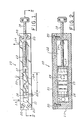
- the flowmeter of the first embodiment of the present invention is indicated generally at 10 and includes a housing 11 having a channel 12 formed therein.
- the housing 11 is made of aluminium bar stock or other suitable material and is sealed with a transparent cover 21 which is made of plexiglass or other suitable material.
- the transparent cover 21 is secured by screws 20 which are threaded into the housing 11.
- the channel 12 is generally rectangular and is approximately 8" (20 cms.) in length and includes an inlet 13 and an outlet 14 through which a continuous flow of fluid may be conducted.
- a flexible membrane 15 of a predetermined length X which is forced to occupy a predetermined length L of a portion of channel 12.
- the flexible membrane 15 is preferably fabricated from mylar or other suitable polymer, or it may be fabricated from a beryllium copper compound or other suitable metal.
- the flexible membrane 15 has dimensions of approximately 0.005" (0.125 mm.) thick, 13/16" (2.03 cms.) wide, and 3" (7.5 cms.) long.
- the flexible membrane 15 should be accurately dimensioned in width such that there is adequate clearance for free movement of the membrane inside the channel 12 without excessive leakage flow. Forcing the flexible membrane 15 to assume length L in a portion of the channel 12 results in a buckling of the membrane which is hereinafter described in greater detail.
- the ends of the flexible membrane 15 are held by membrane holders 16, 17 through the use of clamps, epoxy or a tongue and groove type of arrangement.
- the membrane holders 16, 17 are slotted to allow the passage of fluid therethrough.
- a lead screw 18 is threaded through the housing 11 and coupled to the membrane holder 17, such that the distance L between the membrane holders 1.6, 17 may be precisely adjusted.
- a set screw 22 is threaded through the housing 11 to secure the membrane holder 16 within the channel 12. It should be noted, however, that in further embodiments of the present invention the ends of the flexible membrane 15 may be either free or hinged.
- An optical detector 23 comprised of a light source and a photodetector is disposed within the housing 11 to detect the displacement of the flexible membrane 15 which has a retroreflective strip 24 attached thereto on the side adjacent the detector 23.
- the flexible membrane may be made from a retroreflective material.
- the optical detector 23 may be replaced by other types of detection devices, e.g. pressure transducers, strain gauges, piezoelectric strain gauges, thermistors, capacitance devices, or electromagnetic pick-off devices.
- the flexible membrane 15 itself could be fashioned from a piezoelectric material, and an output signal indicative of the frequency of the flexible membrane could be derived.
- the retroreflective strip 24 causes a pulsed output signal each time the flexible membrane 15 and the retroreflective .strip pass the optical detector 23, thereby providing an indication'of the frequency of the travelling wave which is propagated along the undulating flexible membrane 15 as a result of fluid flowing through the channel 12.
- k 2 P/EI
- P the buckling force applied to the membrane
- E Young's modulus
- I the moment of inertia of the membrane's cross-section
- x length
- w displacement.
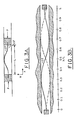
- the conditions which are illustrated in Figure 3A and which are defined by the aforementioned equation (1) are based on the assumptions that the deflections are small and that the membrane 15 follows Hook's law.
- a general solution that satisfies the above differential equation is given by:- with the following boundary conditions:
- the second derivative d 2 w/dx 2 is proportional to a moment which may .be expressed by the following relationship:-
- a wave results and the flexible membrane 15 buckles or undulates from its initial shape to a second shape having a 180° difference in phase.
- a volume of fluid is displaced and a relationship between volumetric flow rate Q and the frequency f of the travelling wave associated with the undulating flexible membrane 15 may also be achieved through mathematical modelling.
- the fluid flows through the channel 12 with an average velocity v ave . Since the travelling wave flowmeter is a positive displacement type flowmeter, the wave velocity equals the average fluid velocity, and the frequency of the wave can be expressed as:-
- the flowmeter 10 utilises the frequency of the flexible member 15 in'order to determine the volumetric flow rate Q.
- a continuous flow of fluid may be conducted into the channel 12 through the inlet 13.
- the incoming fluid is conducted through the slotted passages in the membrane holder 16 and flows along the flexible membrane 15, thereby causing it to undulate.
- the fluid is conducted through the slotted passages-in the membrane holder 17 and out of the channel 12 via the outlet 14.
- the retroreflective strip 24 passes back and forth in front of the optical detector 23, thereby providing a pulsed output signal indicative of the frequency of the undulating flexible member 15.
- This pulsed output signal can be readily applied to a digital electronic processing means such as a counter coupled to a microprocessor to determine the volumetric flow rate in accordance with the algorithms described above.
- the response time of the embodiment of Figures 1 and 2 is, however, relatively slow since it is dictated by the frequency of the travelling wave in the undulating flexible membrane 15. This slow response time may be undesirable in certain circumstances and, therefore, a preferred embodiment is that illustrated in Figures 5, 6 and 7 which measures the flow rate based on a different parameter of the travelling wave in the flexible membrane which gives a much faster response time.
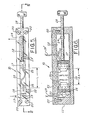
- the basic construction of the flowmeter 10 is similar to that of Figures 1 and 2 and like parts carry the same reference numerals.
- the essential difference between the two embodiments is that the frequency detector of Figures 1 and 2 in the form of the detector 23 and retroreflective member 24 is replaced by two piezoelectric elements 25 attached to the flexible membrane 15 adjacent the respective membrane holders 16 and 17.
- the precise locations of the piezoelectric elements (which may be in the form of a polymer) are predetermined.
- strain gauges of the type having a resistive element whose output is proportional to the amount of deformation may be substituted for the strips of piezoelectric polymer 25.
- the flexible membrane 15 itself may be fabricated from a piezoelectric material, such as a polymer, instead of employing the strips of piezoelectric polymer 25.
- each piezoelectric strip is fabricated from a piece of PVF 2 (polyvinylidene fluoride [-cH 2 cF 2 -] n ) approximately 0.001" (0.025mm) thick which is metallised on both sides. PVF 2 having a sputtered metal coating is a commercially procurable product.
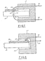
- a wire lead 30 is attached to the metallised piezoelectric strip 25 by a bead of conductive epoxy 32.
- a hole 33 approximately 1/16" (1.6mm) in diameter is drilled through the flexible membrane 15, the latter being attached to the membrane holder 17 by layers of epoxy 35.
- the wire lead 30 is then fed through the hole 33 and nonconductive epoxy is used to affix the metallised piezoelectric strip 25 to the flexible membrane 15.
- a second wire lead 31 is attached to the metallised piezoelectric strip 25 by a bead of conductive epoxy 34.
- the wire leads 30, 31 are held in the membrane holders 16 and 17 by epoxy and are connected to respective pairs of connector pins 19, 19' disposed in the plexiglass cover 21.
- FIG. 8' an alternate technique for affixing the piezoelectric polymer strip 25 to the flexible membrane 15 is illustrated.
- the membrane holder 17 is fabricated from a nonconductive material, or the interior portion is covered with an insulating material.
- the wire leads 30, 31 are attached by conductive epoxy to respective sides of the metallised piezoelectric polymer strip 25.
- the flexible membrane 15 and the metallised piezoelectric polymer strips 25 are attached together by epoxy as well as to the membrane holders 16 and 17 by layers of epoxy 35. As before, the leads 30, 31 are also held in the membrane holders 16 and 17 by epoxy.
- FIGS. 9A and 9B plan and front views illustrate the flexible membrane 15 in a flattened and extended, as opposed to buckled, disposition. Illustrating the flexible membrane 15 in this disposition is useful in explaining an alternative embodiment of the present invention and useful in explaining the relationship of known points on the flexible membrane 15.
- An alternate embodiment of the present invention may be realised by fabricating the entire flexible membrane 15 from the piezoelectric polymer PVF 2 . In known locations on the flexible membrane 15, for example S 1 , S 2 , ... S j , the piezoelectric polymer is metallised. It should be noted that when the flexible membrane 15 is undulating in a travelling wave type of displacement inside the channel 12, locations S 1 , S 2 , ...
- the piezoelectric polymer strips 25 are separated by a substantially constant distance ⁇ X.
- the piezoelectric polymer strips 25 are subject to alternating tension and compression forces which generate output signals on the respective pairs of leads. 30, 31.
- the output signals have a generally sinusoidal waveform.
- the peak-to-peak time difference ⁇ t ij between the two generally sinusoidal waveforms, or the phase difference therebetween, is proportional to the time required for the travelling wave to propagate the distance ⁇ X ij , i.e. the known distance between the piezoelectric polymer strips 25.
- the response time of the travelling wave flowmeter can be made considerably faster by using the velocity of propagation of the travelling wave rather than by using the frequency of the travelling wave as in the embodiment of Figures 1 and 2. It will be further appreciated that by increasing the number of known locations on the flexible membrane 15 at which an output signal is generated, the response time of the travelling wave flowmeter may be made even faster. For example, if the number of known locations is doubled from two to four, then the response time is halved.
- the present invention provides a flowmeter of relatively simple construction and which is substantially insensitive to temperature variations in the fluid the flow rate of which is being measured. Furthermore, the flowmeter can have a relatively fast response time if the parameter of the travelling wave generated in the flexure means by fluid flow which is detected is that of velocity of propagation.
Landscapes
- Physics & Mathematics (AREA)
- Fluid Mechanics (AREA)
- General Physics & Mathematics (AREA)
- Measuring Volume Flow (AREA)
Applications Claiming Priority (4)
| Application Number | Priority Date | Filing Date | Title |
|---|---|---|---|
| US06/210,088 US4358954A (en) | 1980-11-24 | 1980-11-24 | Traveling wave flow meter |
| US210088 | 1980-11-24 | ||
| US06/268,940 US4409830A (en) | 1981-06-01 | 1981-06-01 | Wave velocity detecting schemes for traveling wave flow meter |
| US268940 | 1994-06-30 |
Publications (1)
| Publication Number | Publication Date |
|---|---|
| EP0052992A1 true EP0052992A1 (fr) | 1982-06-02 |
Family
ID=26904799
Family Applications (1)
| Application Number | Title | Priority Date | Filing Date |
|---|---|---|---|
| EP81305419A Withdrawn EP0052992A1 (fr) | 1980-11-24 | 1981-11-17 | Débitmètre |
Country Status (3)
| Country | Link |
|---|---|
| EP (1) | EP0052992A1 (fr) |
| AU (1) | AU551461B2 (fr) |
| CA (1) | CA1177960A (fr) |
Citations (1)
| Publication number | Priority date | Publication date | Assignee | Title |
|---|---|---|---|---|
| DE2924675A1 (de) * | 1978-10-12 | 1980-04-24 | Peter Bauer | Vorrichtung zum messen einer stroemenden fluid-menge |
-
1981
- 1981-11-17 EP EP81305419A patent/EP0052992A1/fr not_active Withdrawn
- 1981-11-18 AU AU77595/81A patent/AU551461B2/en not_active Ceased
- 1981-11-23 CA CA000390634A patent/CA1177960A/fr not_active Expired
Patent Citations (1)
| Publication number | Priority date | Publication date | Assignee | Title |
|---|---|---|---|---|
| DE2924675A1 (de) * | 1978-10-12 | 1980-04-24 | Peter Bauer | Vorrichtung zum messen einer stroemenden fluid-menge |
Also Published As
| Publication number | Publication date |
|---|---|
| CA1177960A (fr) | 1984-11-13 |
| AU7759581A (en) | 1982-06-03 |
| AU551461B2 (en) | 1986-05-01 |
Similar Documents
| Publication | Publication Date | Title |
|---|---|---|
| US4862750A (en) | Vortex shedding fluid velocity meter | |
| US6938496B2 (en) | Vortex flow pickup | |
| EP0048588B1 (fr) | Débitmètre à induction de vortex et procédé de mesure de débit | |
| RU2454633C2 (ru) | Сборочный узел вихревого расходомера кармана, содержащий датчик волоконной решетки брэгга, и способ измерения расхода текучей среды | |
| US4317178A (en) | Multiple velocity traverse flow rate measuring technique | |
| US4448081A (en) | Method and device for the dynamic and density-independent determination of mass flow | |
| US6910387B2 (en) | Vortex flow sensor for measuring fluid flow through a flow tube | |
| EP0152451B1 (fr) | Debitmetre de masse a partage tourbillonnaire pour mesures dans un plan | |
| EP0763718A1 (fr) | Debitmetre | |
| US4864868A (en) | Vortex flowmeter transducer | |
| US20060278015A1 (en) | Device for determination and/or monitoring of the volumetric and/or mass flow of a medium | |
| US6253625B1 (en) | Target flow meters with immersed strain gauges | |
| CA2020530A1 (fr) | Debitmetres a vortex | |
| JPH04505056A (ja) | 渦発生流量計 | |
| US4358954A (en) | Traveling wave flow meter | |
| US4409830A (en) | Wave velocity detecting schemes for traveling wave flow meter | |
| US4984471A (en) | Force transmitting mechanism for a vortex flowmeter | |
| GB2084324A (en) | Vortex Shedding Fluid Flowmeter | |
| CA2459564C (fr) | Compteur d'ecoulement tourbillonnaire | |
| EP0052992A1 (fr) | Débitmètre | |
| WO2000066979A1 (fr) | Debitmetre massique a capteur de force | |
| US7127953B1 (en) | Target flow meters | |
| Keech | The KPC multichannel correlation signal processor for velocity measurement | |
| EP1194746B1 (fr) | Mesure de debit d'ecoulement de plusieurs constituants a l'aide de mesures de pressions non stabilisees | |
| GB2131171A (en) | Vorten flowmeter using optical differential pressure sensor |
Legal Events
| Date | Code | Title | Description |
|---|---|---|---|
| PUAI | Public reference made under article 153(3) epc to a published international application that has entered the european phase |
Free format text: ORIGINAL CODE: 0009012 |
|
| AK | Designated contracting states |
Designated state(s): CH DE FR GB IT LI SE |
|
| 17P | Request for examination filed |
Effective date: 19821102 |
|
| RAP1 | Party data changed (applicant data changed or rights of an application transferred) |
Owner name: VICKERS, INCORPORATED |
|
| STAA | Information on the status of an ep patent application or granted ep patent |
Free format text: STATUS: THE APPLICATION IS DEEMED TO BE WITHDRAWN |
|
| 18D | Application deemed to be withdrawn |
Effective date: 19861104 |
|
| RIN1 | Information on inventor provided before grant (corrected) |
Inventor name: EARLE, RICHARD LEROY Inventor name: DEJONG, JOANNES NICOLAAS MATTHEUS Inventor name: SOMES, RICHARD KENNETH |