EP0053035B1 - Appareil d'alimentation en feuilles - Google Patents
Appareil d'alimentation en feuilles Download PDFInfo
- Publication number
- EP0053035B1 EP0053035B1 EP81305541A EP81305541A EP0053035B1 EP 0053035 B1 EP0053035 B1 EP 0053035B1 EP 81305541 A EP81305541 A EP 81305541A EP 81305541 A EP81305541 A EP 81305541A EP 0053035 B1 EP0053035 B1 EP 0053035B1
- Authority
- EP
- European Patent Office
- Prior art keywords
- sheet
- tube
- shaft
- openings
- blades
- Prior art date
- Legal status (The legal status is an assumption and is not a legal conclusion. Google has not performed a legal analysis and makes no representation as to the accuracy of the status listed.)
- Expired
Links
- 230000009467 reduction Effects 0.000 claims description 7
- 239000000463 material Substances 0.000 claims description 4
- 229920003023 plastic Polymers 0.000 claims description 4
- 239000004033 plastic Substances 0.000 claims description 4
- 238000003384 imaging method Methods 0.000 claims description 2
- 230000032258 transport Effects 0.000 description 21
- 230000007246 mechanism Effects 0.000 description 16
- 238000000926 separation method Methods 0.000 description 11
- 238000012545 processing Methods 0.000 description 10
- 239000002245 particle Substances 0.000 description 7
- 238000012546 transfer Methods 0.000 description 5
- 238000000034 method Methods 0.000 description 4
- 239000000203 mixture Substances 0.000 description 4
- 238000004140 cleaning Methods 0.000 description 3
- 238000011161 development Methods 0.000 description 3
- 239000008187 granular material Substances 0.000 description 3
- 239000000843 powder Substances 0.000 description 3
- 238000013461 design Methods 0.000 description 2
- 239000012530 fluid Substances 0.000 description 2
- 230000000977 initiatory effect Effects 0.000 description 2
- 239000000758 substrate Substances 0.000 description 2
- 230000007723 transport mechanism Effects 0.000 description 2
- 238000006424 Flood reaction Methods 0.000 description 1
- 239000004698 Polyethylene Substances 0.000 description 1
- BUGBHKTXTAQXES-UHFFFAOYSA-N Selenium Chemical compound [Se] BUGBHKTXTAQXES-UHFFFAOYSA-N 0.000 description 1
- 229910052782 aluminium Inorganic materials 0.000 description 1
- XAGFODPZIPBFFR-UHFFFAOYSA-N aluminium Chemical compound [Al] XAGFODPZIPBFFR-UHFFFAOYSA-N 0.000 description 1
- 230000004907 flux Effects 0.000 description 1
- 239000011521 glass Substances 0.000 description 1
- 150000002500 ions Chemical class 0.000 description 1
- 239000003562 lightweight material Substances 0.000 description 1
- 239000000696 magnetic material Substances 0.000 description 1
- 229910052751 metal Inorganic materials 0.000 description 1
- 239000002184 metal Substances 0.000 description 1
- 238000012986 modification Methods 0.000 description 1
- 230000004048 modification Effects 0.000 description 1
- -1 polyethylene Polymers 0.000 description 1
- 229920000573 polyethylene Polymers 0.000 description 1
- 230000008569 process Effects 0.000 description 1
- 230000004044 response Effects 0.000 description 1
- 229910052711 selenium Inorganic materials 0.000 description 1
- 239000011669 selenium Substances 0.000 description 1
- 239000007921 spray Substances 0.000 description 1
Images
Classifications
-
- B—PERFORMING OPERATIONS; TRANSPORTING
- B65—CONVEYING; PACKING; STORING; HANDLING THIN OR FILAMENTARY MATERIAL
- B65H—HANDLING THIN OR FILAMENTARY MATERIAL, e.g. SHEETS, WEBS, CABLES
- B65H5/00—Feeding articles separated from piles; Feeding articles to machines
- B65H5/22—Feeding articles separated from piles; Feeding articles to machines by air-blast or suction device
- B65H5/222—Feeding articles separated from piles; Feeding articles to machines by air-blast or suction device by suction devices
- B65H5/226—Feeding articles separated from piles; Feeding articles to machines by air-blast or suction device by suction devices by suction rollers
-
- B—PERFORMING OPERATIONS; TRANSPORTING
- B65—CONVEYING; PACKING; STORING; HANDLING THIN OR FILAMENTARY MATERIAL
- B65H—HANDLING THIN OR FILAMENTARY MATERIAL, e.g. SHEETS, WEBS, CABLES
- B65H3/00—Separating articles from piles
- B65H3/08—Separating articles from piles using pneumatic force
- B65H3/10—Suction rollers
-
- B—PERFORMING OPERATIONS; TRANSPORTING
- B65—CONVEYING; PACKING; STORING; HANDLING THIN OR FILAMENTARY MATERIAL
- B65H—HANDLING THIN OR FILAMENTARY MATERIAL, e.g. SHEETS, WEBS, CABLES
- B65H2301/00—Handling processes for sheets or webs
- B65H2301/40—Type of handling process
- B65H2301/42—Piling, depiling, handling piles
- B65H2301/423—Depiling; Separating articles from a pile
- B65H2301/4232—Depiling; Separating articles from a pile of horizontal or inclined articles, i.e. wherein articles support fully or in part the mass of other articles in the piles
- B65H2301/42324—Depiling; Separating articles from a pile of horizontal or inclined articles, i.e. wherein articles support fully or in part the mass of other articles in the piles from top of the pile
Definitions
- the present invention relates to a sheet feeding apparatus for moving sheets from a stack and more particularly relates to a simple vacuum assisted impact feeder for removing sheets from the top of such a stack.
- the apparatus is of the kind which includes a generally cylindrical tube mounted in relation to a sheet supply, said tube defining one or more openings positioned along its length opposite said supply; means for creating a pressure reduction inside said tube to attract individual sheets to said tube openings, and drive means rotatably supported inside said tube and extending through said one or more openings for contacting a sheet attracted to said tube and for moving said sheet away from said supply.
- a generally cylindrical tube mounted in relation to a sheet supply, said tube defining one or more openings positioned along its length opposite said supply; means for creating a pressure reduction inside said tube to attract individual sheets to said tube openings, and drive means rotatably supported inside said tube and extending through said one or more openings for contacting a sheet attracted to said tube and for moving said sheet away from said supply.
- the prior art sheet separating and movement initiating mechanisms can be roughly categorized as either impact, vacuum assisted, or a combination of impact and vacuum assisted mechanisms. All three sheet separating techniques have been tried with varying degrees of success. Each has its advantages and disadvantages and is not believed any one of these generic sheet separating mechanisms can be categorically stated to be better than the others.
- Those prior art mechanisms employing vacuum assisted separators only include a source of vacuum which attracts one sheet away from a stack of such sheets and initiates movement away from the stack.
- Two examples of such a vacuum assisted sheet transport mechanism are disclosed in U.S. Patent Nos. 4,121,819 and 4,127,263 to DiFrancesco et al. and Wenthe, respectively. Both document transports illustrated in those patents are vacuum assisted transports which feed documents in sequence from the bottom of a stack of those documents. A bottom most sheet is attracted to a vacuum assisted drive roller which then drives the bottom most sheet away from the stack to a separate location for processing.
- An impact type transport or feeder is one that relies solely upon frictional forces to engage sheets of paper to be transported and drive those sheets away from the stack.
- An example of such an impact type feeder is disclosed in U.S. Patent No. 4,043,549 to Rinehart which has been assigned to the assignee of the present invention.
- the apparatus disclosed in that patent includes a paddle element which is rotated into contact with a bottom most sheet to initiate movement of that sheet away from the stack. Sheet separation is achieved by angled air jets which reduce the frictional forces between a bottom most and other sheets in the stack.
- Other examples of impact type only sheet transport mechanisms comprise paddle wheel elements which also intermittently engage a sheet or document to urge that sheet in a particular direction.
- the sheet feeding apparatus of the invention is characterised in that the drive means comprises a shaft centrally mounted in said tube having at least one radially extending beater blade which extends through said one or more openings during each revolution of said shaft to contact the sheet, and a number of turbine blades mounted to said shaft and responsive to said means for creating a pressure reduction to rotate said shaft.
- the means for creating the pressure reduction preferably comprises a vacuum source which is coupled to the tube's interior.
- a vacuum source which is coupled to the tube's interior.
- Rotatably mounted inside the tube is a shaft concentrically located and mounted for rotation about an axis coincident with a centerline of the cylindrical tube.
- the shaft serves as a mount for a series of turbine blades.
- the turbine blades are responsive to the vacuum source and initiate rotation of the shaft which in turn causes a series of beater blades attached to the shaft to rotate.
- the beater blades are aligned with the one or more openings along the cylindrical tube's length and extend a short distance beyond those openings.
- the beater blades periodically extend through the openings to contact a paper sheet attracted to the tube by the vacuum source. In this way, both sheet separation and initial movement are achieved with a mechanism having only one moving member, the rotating shaft and accompanying turbine and beater blades.
- the present sheet feeding apparatus reduces the incidence of multiple sheet feeding. If two or more sheets are removed from the stack and acquired by the tube, impact forces by the beater blades on the top sheet tend to drive excess sheets back onto the stack.
- Apparatus constructed according to the invention is simple and reliable.
- the vacuum assist separates a top most document to allow the beater blades to periodically rotate into contact with the separated sheet and drive it away from the stack.
- other transports known in the art such as drive rollers or drive belts can be utilized to reposition the sheet for subsequent copier operation. Since these subsequent transports can be used to register, align, and control the timing of the sheet movement, the present transport need only achieve sheet separation and travel initiation.
- the shaft beater and turbine blades all comprise easily constructed plastics material mounted within a metal housing. It should be readily apparent therefore that the cost in fabricating such a device is low. From the above it should be appreciated that one object of the invention has the provision of a reliable yet simple sheet separation and transporting mechanism which can be produced at a low cost while adequately performing the aforementioned desired functions.
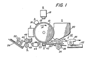
- FIGURE 1 depicts schematically the various components thereof.
- the apparatus for forwarding sheets along a predetermined path is particularly well adapted for use in the electrophotographic printing machine of FIGURE 1, it should become evident from the following discussion that it is equally well suited for use in a wide variety of devices and is not necessarily limited in its application to the particular embodiment shown herein.
- the apparatus of the present invention will be described hereinafter with reference to feeding successive copy sheets, however, one skilled in the art, will appreciate that it may also be employed for feeding successive original documents.
- FIGURE 1 Since the practice of electrophotographic printing is well known in the art, the various processing stations for producing a copy of an original document are represented in FIGURE 1 schematically. Each processing station will be briefly described hereinafter.
- a drum 10 having a photoconductive surface 12 supported by the exterior circumferential surface of a conductive substrate is rotated in the direction of arrow 14 through the various processing stations.
- photoconductive surface 12 may be made from selenium of the type described in U.S. Patent 2,970,906 issued to Bixby in 1961.
- a suitable conductive substrate is made from aluminum.
- drum 10 rotates a photoconductive surface 12 through charging station A.
- Charging station A employs a corona generating device, indicated generally by the reference number 16, to charge photoconductive surface 12 to a relatively high substantially uniform potential.
- a suitable corona generating device is described in U.S. Patent 2,836,725 issued to Vyverberg 1958.
- Exposure station B includes an exposure mechanism, indicated generally by the reference numeral 18, having a stationary, transparent platen, such as a glass plate or the like for supporting an original document thereon. Lamps illuminate the original document. Scanning of the original document is achieved by oscillating a mirror in a timed relationship with the movement of drum 10 or by translating the lamps and lens across the original document so as to create incremental light images which are projected through an apertured slit onto the charged portion of photoconductive surface 12. Irradiation of the charged portion of photoconductive surface 12 records an electrostatic latent image corresponding to the information areas contained within the original document.
- Drum 10 rotates the electrostatic latent image recorded on photoconductive surface 12 to development station C.
- Development station C includes a developer unit, indicated generally by the reference numeral 20, having a housing with a supply of developer mix contained therein.
- the developer mix comprises carrier granules with toner particles adhering triboelectrically thereto.
- the carrier granules are made of a magnetic material with the toner particles being made from a heat settable plastic.
- Developer unit 20 is preferably a magnetic brush development system. A system of this type moves the developer mix through a directional flux field to form a brush thereof.
- the electrostatic latent image recorded on photoconductive surface 12 is developed by bringing the brush of developer mix into contact therewith. In this manner, the toner particles are attracted electrostatically from the carrier granules to the latent image forming a toner powder image on photoconductive surface 12.
- a copy sheet is advanced by a sheet feeding apparatus or transport 60 to transfer station D.
- Sheet feeding apparatus 60 advances successive copy sheets to forwarding rollers 24 and 26.
- Forwarding roller 24 is driven by a motor (not shown) in the direction of arrow 38 and roller 26 rotates in the direction of arrow 36 when roller 24 is in contact therewith.
- feeding apparatus 60 operates to advance the uppermost sheet from stack 62.
- rollers 24 and 26 are spaced from one another. This defines a gap through which the leading edge of the sheet moves. After the leading edge of the sheet is positioned in this gap, rollers 24 and 26 move into contact with the sheet so as to advance the sheet in the direction of arrow 43.
- the sheet is advanced through a chute formed by guides 28 and 40 to transfer station D.
- the detailed structure of forwarding rollers 24 and 26 is described in UK Patent Publication No. 2017655.
- the rollers move into and out of contact with the sheet depending upon whether they are waiting for a sheet to be advanced into the gap.
- the rollers are spaced from one another defining a gap for receiving the sheets.
- the rollers are advancing a sheet, they are moved into contact with the sheet so as to advance it.
- transfer station D in eludes a corona generating device 42 which applies a spray of ions to the back side of the copy sheet. This attracts the toner powder image from photoconductive surface 12 to the copy sheet.
- Fusing station E includes a fuser assembly indicated generally by the reference numeral 46.
- Fuser assembly 46 includes a fuser roll 48 and a backup roll 49 defining a nip therebetween through which the copy sheet passes.
- rollers 52 which may be of the same type as forwarding rollers 24 and 26, to catch tray 54.
- Cleaning station F includes a corona generating device (not shown) adapted to neutralize the remaining electrostatic charge on photoconductive surface 12 and that of the residual toner particles.
- the neutralized toner particles are then cleaned from photoconductive surface 12 by a rotatably mounted fibrous brush (not shown) in contact therewith.
- a discharge lamp (not shown) floods photoconductive surface 12 with light to dissipate any residual electrostatic charge remaining thereon prior to the charging thereof for the next successive imaging cycle.
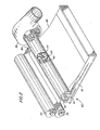
- FIGURE 2 depicts the top feeder system in greater detail.
- FIGURES 2-7 illustrate the sheet transport 60 for separating individual sheets from a stack 62 and imparting initial movement of the separated sheet away from the stack.
- the transport 60 is mounted above the stack 62 and as successive sheets are removed from the stack the transport 60 can be lowered or alternatively the stack 62 can be raised so that the transport 60 continues to function as the height of the stack diminishes.
- the transport 60 attracts an individual sheet 68 away from the stack 62 and moves the sheet to the gap formed by the pair of rollers 24, 26. As noted previously, engagement of the sheet by the rollers 24, 26 causes the sheet to move to the transfer station D.
- the present transport 60 could be utilized to engage and drive any light weight sheet which typically would comprise a paper material.
- the transport 60 can advantageously be utilized for separating either copy sheets to which a toner image is transferred or document originals from which the toner image is created.
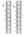
- the transport 60 comprises a hollow cylindrical tube 80 which has been truncated along its length so that a flat tube surface 82 faces the stack 62.
- a vacuum is created inside the tube 80 by a vacuum source 86 coupled to one end of the tube 80.
- the vacuum source 86 When energized the vacuum source 86 causes an air flow through the length of the tube 80 causing a pressure reduction inside the tube. This pressure reduction causes a top most sheet 68 on the stack 62 to be attracted towards the apertures 84.
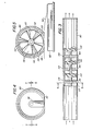
- the transport 60 In addition to separating the top most sheet 68 away from the stack 62, the transport 60 initializes movement of that sheet 68 toward the rollers 24, 26. To provide this movement, the transport 60 further comprises a rotatably mounted shaft 90 journaled for rotation about an axis coincident with the centerline of the tube 80. The shaft 90 is supported in bearings 92 mounted at opposite tube ends.
- turbine blades 110 Mounted along the length of the shaft 90 are a series of turbine blades 110 which respond to fluid flow along the tube 80 by rotating the shaft 90.
- the orientation of the turbine blades 110 is such that air flow along the tube length rotates the shaft in a clockwise sense as seen in the FIGURE 1 illustration.
- the radial dimension of the turbine blades 110 is slightly less than the inside diameter of the tube 80 to prevent the blades 110 from contacting the tube's flat bottom surface 82.
- the beater blades 112 Spaced at locations between the turbine blades 110 are three beater blades 112 which are connected to and rotate with the shaft 90.
- the beater blades 112 extend radially away from the shaft 90 a distance greater than the inside diameter of the tube 80.
- a slot or region of increased diameter 114 has been machined into the tube 80 which allows unimpeded rotation of those blades 112.
- the beater blades 112 are aligned with the apertures 84 and are of such a length that they periodically extend a distance beyond the flat tube surface 82 as they are driven by the rotating shaft 90.
- the blades 112 are equally spaced about the shaft so that each 120° revolution of the shaft 90 causes a beater blade to extend through its associated aperture 84.
- the above described configuration provides a simplified drive mechanism for initializing sheet movement away from the stack 62.
- Rotational motion of the shaft causes the sheet 68 to be driven away from the stack since that sheet 68 is periodically contacted by the rotating beater blades 112.
- a single source of power i.e., the vacuum source 86 attracts the sheet 68 away from the stack and also by rotating the shaft 90 drives the sheet 68 away from the stack to the rollers 22, 24.
- the driving and/or sheet attraction forces can be adjusted to suit a particular application. By reducing the number of beater blades, for example, the driving force can be reduced while the attraction force is maintained.
- the driving force can be reduced while the attraction force is maintained.
- only alternate apertures along the tube 80 have beater blades 114 mounted to extend therethrough and contact the sheet 68.
- a more powerful vacuum can be used to increase the fluid flow rate through the tube to speed sheet separation for high throughput applications.
- Sheet feeding can be terminated by stopping the vacuum source 86 so that the shaft 90 ceases its rotation and the sheets are no longer attracted from the stack 62.
- the shaft 90, turbine blades 110 and beater blades 112 are all constructed from a light weight material, which in the preferred embodiment comprises a polyethylene plastic material. Since vacuum sources are often used in xerographic copier environment to provide other transport functions, the present transport design will typically require no additional. vacuum source with the possible requirement, however, that a larger vacuum source be designed into the copier.
- the transport 10 could be used as a bottom feeder if an air flow mechanism is aimed at the stack 62 to reduce normal downward forces on the bottom sheet exerted by the remainder of the stack while allowing the bottom most sheet to be driven by the beater blades 112.
Landscapes
- Engineering & Computer Science (AREA)
- Mechanical Engineering (AREA)
- Sheets, Magazines, And Separation Thereof (AREA)
Claims (5)
Applications Claiming Priority (2)
| Application Number | Priority Date | Filing Date | Title |
|---|---|---|---|
| US209579 | 1980-11-24 | ||
| US06/209,579 US4348021A (en) | 1980-11-24 | 1980-11-24 | Sheet feeding apparatus |
Publications (2)
| Publication Number | Publication Date |
|---|---|
| EP0053035A1 EP0053035A1 (fr) | 1982-06-02 |
| EP0053035B1 true EP0053035B1 (fr) | 1985-02-20 |
Family
ID=22779338
Family Applications (1)
| Application Number | Title | Priority Date | Filing Date |
|---|---|---|---|
| EP81305541A Expired EP0053035B1 (fr) | 1980-11-24 | 1981-11-24 | Appareil d'alimentation en feuilles |
Country Status (5)
| Country | Link |
|---|---|
| US (1) | US4348021A (fr) |
| EP (1) | EP0053035B1 (fr) |
| JP (1) | JPS57107344A (fr) |
| CA (1) | CA1188336A (fr) |
| DE (1) | DE3169111D1 (fr) |
Families Citing this family (3)
| Publication number | Priority date | Publication date | Assignee | Title |
|---|---|---|---|---|
| GB2138406B (en) * | 1983-04-20 | 1986-11-26 | R Clark Dubois | Paper-tray-and-feeder for photocopy machine |
| US4674735A (en) * | 1983-12-07 | 1987-06-23 | R. Clark DuBois | Automatic sheet feeder for copiers and other machines having sheet transport mechanisms and assemblies therewith |
| JPH0760938A (ja) * | 1993-08-23 | 1995-03-07 | Riso Kagaku Corp | シート搬送装置 |
Family Cites Families (9)
| Publication number | Priority date | Publication date | Assignee | Title |
|---|---|---|---|---|
| DE1284664B (de) * | 1965-07-27 | 1968-12-05 | Siemens Ag | Pneumatisch steuerbare Transporteinrichtung |
| US3484099A (en) * | 1967-04-26 | 1969-12-16 | Dick Co Ab | Rotary sheet feeding and separating assembly |
| US3630516A (en) * | 1970-03-23 | 1971-12-28 | Stromberg Datagraphix Inc | Sheet-feeding apparatus |
| US3998449A (en) * | 1975-06-30 | 1976-12-21 | F. L. Smithe Machine Company, Inc. | Method and apparatus for feeding items from a stack |
| US4043549A (en) * | 1975-11-24 | 1977-08-23 | Xerox Corporation | Impact feeder |
| US4121819A (en) * | 1977-06-20 | 1978-10-24 | Eastman Kodak Company | Rotary vacuum feeder/transporter |
| US4127263A (en) * | 1977-06-27 | 1978-11-28 | Eastman Kodak Company | Port-closure for vacuum sheet feeder |
| JPS5418578A (en) * | 1977-07-11 | 1979-02-10 | Ricoh Co Ltd | Pneumatic sheet feeding apparatus |
| JPS5435966A (en) * | 1977-08-24 | 1979-03-16 | Toshiba Corp | Paper pieces feeding mechanism |
-
1980
- 1980-11-24 US US06/209,579 patent/US4348021A/en not_active Expired - Lifetime
-
1981
- 1981-10-29 CA CA000389064A patent/CA1188336A/fr not_active Expired
- 1981-11-05 JP JP56178224A patent/JPS57107344A/ja active Pending
- 1981-11-24 DE DE8181305541T patent/DE3169111D1/de not_active Expired
- 1981-11-24 EP EP81305541A patent/EP0053035B1/fr not_active Expired
Also Published As
| Publication number | Publication date |
|---|---|
| JPS57107344A (en) | 1982-07-03 |
| US4348021A (en) | 1982-09-07 |
| EP0053035A1 (fr) | 1982-06-02 |
| DE3169111D1 (en) | 1985-03-28 |
| CA1188336A (fr) | 1985-06-04 |
Similar Documents
| Publication | Publication Date | Title |
|---|---|---|
| US3578859A (en) | Mechanical stripping apparatus | |
| EP0541260B1 (fr) | Appareil d'ajustement d'une feuille par rotation et déplacement latéral | |
| US5219159A (en) | Translating nip registration device | |
| US5775690A (en) | Two step optimized stalled roll registration and deskew | |
| EP0485167B1 (fr) | Appareil et procédé d'alignement et de positionnement combinés de feuilles à copier | |
| US5288062A (en) | High capacity compiler with vertically adjustable sheet discharge and acquire means | |
| GB2026441A (en) | Transverse belt registering apparatus | |
| US4381860A (en) | Paddle wheel retard feeder | |
| US5149077A (en) | Hybrid nudger roll | |
| US4487407A (en) | Trail edge copy registration system | |
| US5346199A (en) | Adjustable nudger roll normal force using multiple springs | |
| US4359219A (en) | Direct control paddle wheel | |
| JPS5885449A (ja) | コピ−シ−トハンドリング装置 | |
| US4647032A (en) | Sheet delivering device for business machine | |
| US5300994A (en) | Transfer system including a cam actuated segmented flexible transfer assist blade | |
| US4364550A (en) | Corrugation venturi paper feeder | |
| EP0425249B1 (fr) | Copieurs avec systèmes d'alignement latéral | |
| US4994864A (en) | Copy sheet skew adjustment device | |
| EP0053035B1 (fr) | Appareil d'alimentation en feuilles | |
| US4496144A (en) | Paddle wheel feeder with normal force optimization and blade control | |
| US3930725A (en) | Multiple sheet feeding system for electrostatographic printing machines | |
| US3781004A (en) | Conveying system for electrostatographic printing machines | |
| US4391510A (en) | Voice coil actuator registration system | |
| EP0378005B1 (fr) | Dispositif de déviation pour feuille de copie | |
| US5348282A (en) | Self adjusting feed roll |
Legal Events
| Date | Code | Title | Description |
|---|---|---|---|
| PUAI | Public reference made under article 153(3) epc to a published international application that has entered the european phase |
Free format text: ORIGINAL CODE: 0009012 |
|
| AK | Designated contracting states |
Designated state(s): DE GB |
|
| 17P | Request for examination filed |
Effective date: 19821004 |
|
| GRAA | (expected) grant |
Free format text: ORIGINAL CODE: 0009210 |
|
| AK | Designated contracting states |
Designated state(s): DE GB |
|
| REF | Corresponds to: |
Ref document number: 3169111 Country of ref document: DE Date of ref document: 19850328 |
|
| PLBE | No opposition filed within time limit |
Free format text: ORIGINAL CODE: 0009261 |
|
| STAA | Information on the status of an ep patent application or granted ep patent |
Free format text: STATUS: NO OPPOSITION FILED WITHIN TIME LIMIT |
|
| 26N | No opposition filed | ||
| PGFP | Annual fee paid to national office [announced via postgrant information from national office to epo] |
Ref country code: DE Payment date: 19891002 Year of fee payment: 9 |
|
| PGFP | Annual fee paid to national office [announced via postgrant information from national office to epo] |
Ref country code: GB Payment date: 19891031 Year of fee payment: 9 |
|
| PG25 | Lapsed in a contracting state [announced via postgrant information from national office to epo] |
Ref country code: GB Effective date: 19901124 |
|
| GBPC | Gb: european patent ceased through non-payment of renewal fee | ||
| PG25 | Lapsed in a contracting state [announced via postgrant information from national office to epo] |
Ref country code: DE Effective date: 19910801 |