EP0053052A1 - Interferometrische Einrichtung zur Echtzeit-Sichtbarmachung der Verformungen von schwingenden Gegenständen - Google Patents
Interferometrische Einrichtung zur Echtzeit-Sichtbarmachung der Verformungen von schwingenden Gegenständen Download PDFInfo
- Publication number
- EP0053052A1 EP0053052A1 EP81401649A EP81401649A EP0053052A1 EP 0053052 A1 EP0053052 A1 EP 0053052A1 EP 81401649 A EP81401649 A EP 81401649A EP 81401649 A EP81401649 A EP 81401649A EP 0053052 A1 EP0053052 A1 EP 0053052A1
- Authority
- EP
- European Patent Office
- Prior art keywords
- radiation
- interferometry device
- crystal
- deformations
- vibrating
- Prior art date
- Legal status (The legal status is an assumption and is not a legal conclusion. Google has not performed a legal analysis and makes no representation as to the accuracy of the status listed.)
- Granted
Links
- 238000012800 visualization Methods 0.000 title claims abstract description 6
- 239000000463 material Substances 0.000 claims abstract description 23
- 239000013078 crystal Substances 0.000 claims description 47
- 238000005305 interferometry Methods 0.000 claims description 16
- 230000005855 radiation Effects 0.000 claims description 16
- 230000005684 electric field Effects 0.000 claims description 8
- 230000001427 coherent effect Effects 0.000 claims description 6
- 239000013307 optical fiber Substances 0.000 claims description 5
- JCXGWMGPZLAOME-UHFFFAOYSA-N bismuth atom Chemical compound [Bi] JCXGWMGPZLAOME-UHFFFAOYSA-N 0.000 claims description 4
- 229910000416 bismuth oxide Inorganic materials 0.000 claims description 4
- VYPSYNLAJGMNEJ-UHFFFAOYSA-N Silicium dioxide Chemical compound O=[Si]=O VYPSYNLAJGMNEJ-UHFFFAOYSA-N 0.000 claims description 2
- YBMRDBCBODYGJE-UHFFFAOYSA-N germanium oxide Inorganic materials O=[Ge]=O YBMRDBCBODYGJE-UHFFFAOYSA-N 0.000 claims description 2
- PVADDRMAFCOOPC-UHFFFAOYSA-N oxogermanium Chemical compound [Ge]=O PVADDRMAFCOOPC-UHFFFAOYSA-N 0.000 claims description 2
- 229910052814 silicon oxide Inorganic materials 0.000 claims description 2
- 238000005210 holographic interferometry Methods 0.000 abstract description 3
- 238000009659 non-destructive testing Methods 0.000 abstract 1
- 230000008878 coupling Effects 0.000 description 9
- 238000010168 coupling process Methods 0.000 description 9
- 238000005859 coupling reaction Methods 0.000 description 9
- 238000010586 diagram Methods 0.000 description 5
- 230000003321 amplification Effects 0.000 description 4
- 230000006870 function Effects 0.000 description 4
- 238000003199 nucleic acid amplification method Methods 0.000 description 4
- 238000012546 transfer Methods 0.000 description 4
- 238000000034 method Methods 0.000 description 3
- 230000000737 periodic effect Effects 0.000 description 3
- 238000010521 absorption reaction Methods 0.000 description 2
- 230000003993 interaction Effects 0.000 description 2
- 230000003287 optical effect Effects 0.000 description 2
- 230000010363 phase shift Effects 0.000 description 2
- 230000008569 process Effects 0.000 description 2
- 230000002787 reinforcement Effects 0.000 description 2
- 230000008901 benefit Effects 0.000 description 1
- 230000015572 biosynthetic process Effects 0.000 description 1
- 238000012822 chemical development Methods 0.000 description 1
- 230000001066 destructive effect Effects 0.000 description 1
- 238000001514 detection method Methods 0.000 description 1
- 230000009365 direct transmission Effects 0.000 description 1
- 230000000694 effects Effects 0.000 description 1
- 239000000835 fiber Substances 0.000 description 1
- 238000001093 holography Methods 0.000 description 1
- 238000005286 illumination Methods 0.000 description 1
- 230000002452 interceptive effect Effects 0.000 description 1
- 238000005259 measurement Methods 0.000 description 1
- 230000003446 memory effect Effects 0.000 description 1
- 230000001902 propagating effect Effects 0.000 description 1
- 238000000926 separation method Methods 0.000 description 1
- 238000012360 testing method Methods 0.000 description 1
- 230000032258 transport Effects 0.000 description 1
Images


Classifications
-
- G—PHYSICS
- G01—MEASURING; TESTING
- G01B—MEASURING LENGTH, THICKNESS OR SIMILAR LINEAR DIMENSIONS; MEASURING ANGLES; MEASURING AREAS; MEASURING IRREGULARITIES OF SURFACES OR CONTOURS
- G01B9/00—Measuring instruments characterised by the use of optical techniques
- G01B9/02—Interferometers
- G01B9/021—Interferometers using holographic techniques
-
- Y—GENERAL TAGGING OF NEW TECHNOLOGICAL DEVELOPMENTS; GENERAL TAGGING OF CROSS-SECTIONAL TECHNOLOGIES SPANNING OVER SEVERAL SECTIONS OF THE IPC; TECHNICAL SUBJECTS COVERED BY FORMER USPC CROSS-REFERENCE ART COLLECTIONS [XRACs] AND DIGESTS
- Y10—TECHNICAL SUBJECTS COVERED BY FORMER USPC
- Y10S—TECHNICAL SUBJECTS COVERED BY FORMER USPC CROSS-REFERENCE ART COLLECTIONS [XRACs] AND DIGESTS
- Y10S359/00—Optical: systems and elements
- Y10S359/902—Holographic interferometer
Definitions
- the invention relates to devices for viewing, by holographic interferometry in real time, deformations of vibrating or deformable structures.
- photosensitive electro-optical materials such as BSO (bismuth and silicon oxide) or BGO (bismuth and germanium oxide).
- BSO bismuth and silicon oxide
- BGO bismuth and germanium oxide
- the network of fringes created by the interference of the wave front coming from the object and the reference wave front induces, in real time, to the time of the registration of the material, a network of index strata, constituting a hologram characteristic of the object wavefront. It diffracts part of the energy of the incident reference wavefront according to a diffracted wave whose wavefront is isomorphic to the object wavefront. If we have a mirror perpendicular to the path of the reference wave transmitted by the crystal, to return this reference wave on the crystal, the network of index strata inscribed in the crystal gives rise, from this reflected reference beam, to a conjugate wave of the object wave.
- This device is intended either to highlight the slow deformation of an object between two exposures, or to study the rapid vibrations of an object or part of an object. In the latter case, if the exposure time of the recording material is large compared to the period. vibration and if the maximum amplitude Ae of the deformation does not exceed a few tens of times the wavelength X of the radiation, the image obtained then corresponds to the image of the object to be analyzed modulated by black fringes, corresponding to the zeros of the Bessel function J 2 ( ⁇ e).
- This device works by retroreflection of the reference wave, generation of the conjugate wavefront in the recording material, and separation of this conjugate wavefront from the incident object wavefront by means of a semi-transparent plate. .
- the reference wave thus passes twice through the crystal, and taking into account the absorption coefficients at the wavelengths used, around 500 nm, this results in an optimal thickness of material, of the order of 2 mm. .
- the rate of modulation of the fringes depends on the ratio of the interfering beams.
- this ratio is of the order of 10 -3 to 10- 4 , which corresponds to an extremely low modulation rate of the fringes, of the order of 2.10 -2 .
- the energy available in the image is much lower,. by a factor of 4.10- 4.
- Another consequence of the low modulation rate is that the registration time is longer.
- the wave coupling results in a significant transfer of energy from the reference beam to the object beam after crossing the crystal.
- the intensity of the directly transmitted object beam is increased, in practice, by a factor of 2 to 3 in the presence of the reference beam which acts, under these conditions, as a pump wave.
- the invention specifically relates to an interferometry device for the real-time visualization of the deformations of a vibrating structure, comprising a photosensitive electro-optical recording material in which a hologram is recorded in volume, in real time. corresponding to the deformations of this vibrating structure on the basis of the interference in the volume of the material of an incident object beam scattered by the vibrating structure and of a reference beam and of means for displaying the interferogram of the resulting vibrating structure reading the hologram recorded by the material, characterized in that these display means collect the interferogram of the vibrating structure on the object beam emerging from the recording material.
- FIG. 1 the case of a fixed diffusing object, of any shape, from which the object wave 2 emits a wavefront front O.
- a thick single crystal 1 cut out of a photoconductive electro-optical material, for example BSO, is arranged on the path of this object wave 2.
- this object wave interferes with a reference wave 3, with a plane wavefront.
- the network of interference fringes 11 thus created generates, in real time, in the crystal, a network of strata of index 12, after a writing time T.
- This network of strata diffracts part of the energy of the reference wave 3 into a diffracted wave 4, the wave front of which is isomorphic to the object wave front Eo.
- the photo-induced network can be exactly phase-shifted by with respect to the incident illumination network, which has the consequence that the diffracted wave 4 is strictly superimposed on the transmitted object wave 5; everything happens as if the transmitted object wave was enriched with a fraction of the energy of the reference wave. If the thickness of the crystal concerned by the interference of the two beams is large, of the order of 1 cm, the transmitted object beam can be considerably reinforced, by a factor of 2 to 3.
- this reinforced object wave interferes again with the reference beam, which accentuates the modulation of the fringes, and creates a contribution of energy on the object beam a little more important, and thus step by step, throughout the thickness of the crystal in which the object and reference beams interfere, because the new photo-induced network is always in phase with the main network, thanks to the phase shift between the interference network and the index network.
- the fringe modulation rate is greater than on the input face, as shown in Figure 2 in b.
- the interaction length in the medium is sufficient, a notable increase in the intensity of the emerging object beam can be obtained, practically by a factor of 2 to 3.
- the directly transmitted object beam exits with an intensity of 0.1 due to the absorption in the crystal, and the diffracted beam according to this object beam has an intensity of 0.2, which ultimately represents a significant transfer of energy from the reference beam to the object signal.
- the amplification of the diffracted beam due to the wave coupling in a thick crystal is shown in the diagram of FIG. 3, compared to the intensity of the diffracted beam in the device of the prior art.
- the straight line 41 represents the intensity of the directly transmitted object beam, in the absence of the pump beam 3, in the case of the present invention, as in the case of the prior art. This intensity is constant from time 0 when the incident object beam arrives on the BSO crystal.
- Curve 42 shows the establishment at the end of time T of the diffracted object beam in the case of the present invention, with an intensity two to three times greater than that of the directly transmitted object beam.
- Curve 43 shows the establishment of the diffracted beam in the case of the device of the prior art, with a low intensity compared to the intensity of the directly transmitted object beam, the energy of these diffracted beams being, in both cases , taken from the reference beam.
- the crystal 1 may or may not be subjected to a transverse electric field, as shown by the arrow 6 in FIG. 1, the phase shift of; between the interference network and the index network is established automatically ment, but the efficiency of the amplification phenomenon is higher the higher the applied electric field, typically between 10 and 20 kV.cm -1 .
- the registration saturation. of the index network from the interference fringe network is not instantaneous and requires a certain time T , typically 100 ms, and the same is true for the erasure of the network.
- T typically 100 ms
- a vibrating and diffusing object emits at every instant an object wave whose wave front is different, and more exactly, presents periodic variations.
- this object wave inscribes in the crystal with the reference beam an index network.
- the erasure is not instantaneous, there is, in the crystal, coexistence of all the diffraction gratings corresponding to all the states of the object.
- the image obtained corresponds to the image of the object to be analyzed modulated by black fringes.
- the transfer of energy from the reference beam to the object beam is notable for an interaction length of 1 cm.
- the preferred orientation of the single crystal with respect to the direction of the electric field 6 is that which is shown in FIG. 4, that is to say the electric field perpendicular to the faces 001 of the crystal.
- the incidence of the beams on the face 110 or 110 and which determines the pitch of the fringes, is optimal around 20 to 30 °, for example + 20 ° for the object beam, - 20 ° for the reference beam.
- the time constants T used for the transfer of energy from the reference beam to the object beam are practically independent of the ratio of the intensities of the incident beams, reference and object, T varies from 50 to 100 ms when this ratio varies from 1 to 1000.
- the amplification coefficient obtained on the transmitted object beam is also independent dant of this ratio as soon as it is greater than 10 and is a nonlinear function of the electric field applied to the crystal when this field exceeds a threshold value of 10 kV.cm -1 . It is also technologically difficult to work at more than 20 kV.cm -1 .
- Such a medium used under the conditions which have just been described, is particularly suitable. the production of an interferometry device for visualizing the deformations of vibrating structures.
- This device is intended to display the deformations of the vibrating object 52, illuminated by a light source 51, by means of a diffuser 53.
- This object 52 re-diffuses an object beam 2 towards the recording medium 1.
- This medium is, for example, a single crystal of BSO, of cubic shape and dimensions 1cm x 1cm x 1cm.
- This crystal is subjected to an electric field of the order of 10 kV.cm -1 .
- two electrodes 6 and 7 are arranged on two parallel faces of the crystal, and connected to the two terminals of a voltage generator 10.
- a reference beam 3, parallel, coherent with the object beam 2 is formed from the light source 55, by means of the beam expander 56 and sent to the single crystal 1.
- the single crystal 1 advantageousously, it covers very widely the entrance face of the crystal.
- a lens 57 On the path of the transmitted object beam 5, there is a lens 57, intended to form the image of the object on a detector 58, for example vidicon connected to a television screen or polaroid camera.
- a network of fixed diffraction strata 12, or interferometric hologram is recorded in the medium and part 4 of the reference beam diffracted by this network and superimposed on the transmitted object beam 5, forms on the input face of the vidicon 58, the interferogram of the vibrating object 52.
- the image received by the detector 58 contains a network of black fringes fixed, corresponding to the vibrating parts of the object. This network of fringes is superimposed on a continuous background representing the image of the object formed from the directly transmitted object beam 5.
- the contrast between the interferogram and the continuous background is sufficient to detect in direct transmission, which was not the case with the previous device described in application No. 77 086 27, where it was necessary either to shut off the object beam during the reading of the interferogram, either operate by retroreflection and separate by a semi-transparent plate the beam carrying the interferogram from the main object beam.
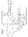
- FIG. 6 A first variant of this device is shown in FIG. 6.
- This variant has the main characteristics of the device described above.
- the essential difference lies in the mode of lighting the object and obtaining the reference beam.
- All the light energy used in the operation of the device is supplied by a laser 61.
- the beam emitted by this laser 61 is separated in two and coupled to two optical fibers 64 and 65 via the coupling means 62, comprising for example a semi-transparent plate 63.
- the fiber 65 is intended to illuminate the vibrating object 52 which diffuses the object beam 2 towards the device.
- the optical fiber 64 transports the reference radiation towards the entry face of the crystal .
- the reference radiation arrives on the crystal in a parallel beam with a large opening after crossing the beam expander 56.
- the photosensitive electro-optical crystal 1, BSO for example is polarized around 10 kV.cm -1 by the source. voltage 10 whose two terminals are. connected to the electrodes 6 and 7 carried by two parallel faces of the crystal. Inside the crystal, and on all its thickness, the two beams object 2 and reference 3 interfere.
- the network of index strata forming the interferometric hologram of the vibrating object diffracts a fraction of the reference beam according to the trajectory of the directly transmitted object beam.
- the image of this hologram or interfogram is formed on the input face of the vidicon 59 via the lens 57. This image can be viewed on the screen 50.
- FIG. 6 shows the interferometry device inside an enclosure delimited by a wall 67, provided with a window 68 allowing the passage of the object beam towards the device, and a passage 69 for the optical fiber intended to illuminate the object.
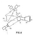
- FIG. 7 Another variant of this device is shown in FIG. 7.
- the black fringes observed on the interferogram correspond to the parts of the object which do not vibrate.
- the reference wave is shifted in frequency by an amount equal to the object's vibration frequency.
- the restored image then includes black fringes corresponding to the zeros of the Bessel function J1 2 ( ⁇ ⁇ e).
- the frequency offset is obtained by placing an acousto-optic tank 71 on the path of the reference beam.
- the object and reference light radiation come from the same light source 72, for example a laser, and separated by the semi-transparent plate 73.
- the light beam from the object is sent to the object via the diffuser 74.
- the object broadcasts it back to the crystal 1.
- the reference beam from the semi-transparent plate 73, -is collimated by the lens 75, slid in frequency by the acousto-optic tank 71, widened by the beam expander 56 and sent to the crystal 1.
- the establishment of the hologram and the visualization of the interferogram is done according to the method described above: formation of the image using the lens 57, on the input face of the vidicon 59, and visualization on the screen 50
- the image is formed on the sensitive film 83 of a polaroid camera 84, with an exposure time corresponding to N times the time ⁇ of establishment of the wave coupling.
- the interferogram of large objects is thus obtained, taking advantage of the properties of coherent optics for holographic inscription, but with an image quality approaching that of incoherent optics.
- the interferogram is no longer a network of fixed fringes whose characteristics are linked to the amplitude of the deformations., But it nevertheless gives information on the area of the object which is deformed.
Landscapes
- Physics & Mathematics (AREA)
- General Physics & Mathematics (AREA)
- Holo Graphy (AREA)
- Instruments For Measurement Of Length By Optical Means (AREA)
- Measurement Of Mechanical Vibrations Or Ultrasonic Waves (AREA)
Applications Claiming Priority (2)
| Application Number | Priority Date | Filing Date | Title |
|---|---|---|---|
| FR8024966 | 1980-11-25 | ||
| FR8024966A FR2494866A1 (fr) | 1980-11-25 | 1980-11-25 | Dispositif d'interferometrie pour la visualisation en temps reel des deformations de structures vibrantes |
Publications (2)
| Publication Number | Publication Date |
|---|---|
| EP0053052A1 true EP0053052A1 (de) | 1982-06-02 |
| EP0053052B1 EP0053052B1 (de) | 1985-01-09 |
Family
ID=9248318
Family Applications (1)
| Application Number | Title | Priority Date | Filing Date |
|---|---|---|---|
| EP81401649A Expired EP0053052B1 (de) | 1980-11-25 | 1981-10-20 | Interferometrische Einrichtung zur Echtzeit-Sichtbarmachung der Verformungen von schwingenden Gegenständen |
Country Status (5)
| Country | Link |
|---|---|
| US (1) | US4492468A (de) |
| EP (1) | EP0053052B1 (de) |
| JP (1) | JPS57114825A (de) |
| DE (1) | DE3168192D1 (de) |
| FR (1) | FR2494866A1 (de) |
Cited By (1)
| Publication number | Priority date | Publication date | Assignee | Title |
|---|---|---|---|---|
| DE3718327A1 (de) * | 1987-06-01 | 1988-12-22 | Rottenkolber Holo System Gmbh | Vorrichtung zur durchfuehrung von holographischer interferometrie |
Families Citing this family (16)
| Publication number | Priority date | Publication date | Assignee | Title |
|---|---|---|---|---|
| US4612797A (en) * | 1984-06-27 | 1986-09-23 | Rockwell International Corporation | Leak locating and mapping system and method |
| JPS61148327A (ja) * | 1984-12-22 | 1986-07-07 | Toshiba Corp | 音場可視化装置 |
| US5396368A (en) * | 1985-01-14 | 1995-03-07 | Rockwell International Corporation | Flexible rejection filter (U) |
| US4707137A (en) * | 1985-10-25 | 1987-11-17 | Laser Magnetic Storage International Company | Device and method for testing the wave front quality of optical components |
| US5006813A (en) * | 1986-02-10 | 1991-04-09 | Rockwell International Corporation | Nonlinear optical doppler imaging amplifier |
| US4703992A (en) * | 1986-05-27 | 1987-11-03 | Rockwell International Corporation | Laser beam cleanup by photorefractive two-way mixing |
| US4877297A (en) * | 1988-04-29 | 1989-10-31 | Rockwell International Corporation | Reconfigurable 0ptical interconnect using dynamic hologram |
| US4938596A (en) * | 1989-01-05 | 1990-07-03 | The University Of Rochester | Phase conjugate, common path interferometer |
| FR2711878B1 (fr) * | 1993-10-29 | 1995-12-15 | Thomson Csf | Dispositif de visualisation couleurs et procédé de réalisation. |
| US5827971A (en) * | 1996-05-31 | 1998-10-27 | Lockheed Martin Idaho Technologies Company | Optical vibration detection spectral analysis assembly and method for detecting vibration in an object of interest |
| FR2755516B1 (fr) | 1996-11-05 | 1999-01-22 | Thomson Csf | Dispositif compact d'illumination |
| US6134006A (en) * | 1998-02-25 | 2000-10-17 | Becthel Bwxt Idaho, Llc | Imaging photorefractive optical vibration measurement method and device |
| FR2819061B1 (fr) * | 2000-12-28 | 2003-04-11 | Thomson Csf | Dispositif de controle de polarisation dans une liaison optique |
| FR2860291B1 (fr) * | 2003-09-26 | 2005-11-18 | Thales Sa | Dispositif capteur de vitesse de rotation interferometrique a fibre optique |
| DE102007010387B4 (de) * | 2007-03-03 | 2013-02-21 | Polytec Gmbh | Interferometer zur optischen Vermessung eines Objekts |
| WO2026028067A1 (en) * | 2024-07-31 | 2026-02-05 | Consiglio Nazionale Delle Ricerche | System and method for detecting a displacement or a deformation of a building structure |
Citations (2)
| Publication number | Priority date | Publication date | Assignee | Title |
|---|---|---|---|---|
| FR2385079A1 (fr) * | 1977-03-23 | 1978-10-20 | Thomson Csf | Dispositif de visualisation, par interferometrie holographique, des deformations de structures deformables |
| FR2416452A2 (fr) * | 1977-03-23 | 1979-08-31 | Thomson Csf | Dispositif de visualisation, par interferometrie holographique, des deformations de structures deformables |
Family Cites Families (1)
| Publication number | Priority date | Publication date | Assignee | Title |
|---|---|---|---|---|
| FR2395534A1 (fr) * | 1977-06-24 | 1979-01-19 | Thomson Csf | Dispositif d'imagerie acousto-optique a detection holographique coherente en temps reel |
-
1980
- 1980-11-25 FR FR8024966A patent/FR2494866A1/fr active Granted
-
1981
- 1981-10-20 EP EP81401649A patent/EP0053052B1/de not_active Expired
- 1981-10-20 DE DE8181401649T patent/DE3168192D1/de not_active Expired
- 1981-11-16 US US06/321,701 patent/US4492468A/en not_active Expired - Fee Related
- 1981-11-24 JP JP56188254A patent/JPS57114825A/ja active Pending
Patent Citations (2)
| Publication number | Priority date | Publication date | Assignee | Title |
|---|---|---|---|---|
| FR2385079A1 (fr) * | 1977-03-23 | 1978-10-20 | Thomson Csf | Dispositif de visualisation, par interferometrie holographique, des deformations de structures deformables |
| FR2416452A2 (fr) * | 1977-03-23 | 1979-08-31 | Thomson Csf | Dispositif de visualisation, par interferometrie holographique, des deformations de structures deformables |
Non-Patent Citations (3)
| Title |
|---|
| Optics Communications, Volume 34, No. 1, Juillet 1980 Amsterdam (NL) A. MARRAKCHI et al. "Application of Phase Conjugation in Bi12SiO20 Crystals to Mode Pattern Visualisation of Diffuse Vibrating Structures", pages 15-18 * pages 15, 16, 18 * * |
| Optics Letters, Volume 4, No. 1, Janvier 1979 New York (US) J. HUIGNARD et al. "Phase-Conjugate Wavefront Generation via Real-Time Holography in Bi12SiO20 Crystals", pages 21-23 * en entier * * |
| Optics Letters, Volume 5, No. 10, Octobre 1980 New York (US) J. HUIGNARD et al. "Speckle-Free Imaging in Four-Wave Mixing Experiments with Bi12SiO20 Crystals" pages 436-437 * en entier * * |
Cited By (1)
| Publication number | Priority date | Publication date | Assignee | Title |
|---|---|---|---|---|
| DE3718327A1 (de) * | 1987-06-01 | 1988-12-22 | Rottenkolber Holo System Gmbh | Vorrichtung zur durchfuehrung von holographischer interferometrie |
Also Published As
| Publication number | Publication date |
|---|---|
| JPS57114825A (en) | 1982-07-16 |
| US4492468A (en) | 1985-01-08 |
| FR2494866B1 (de) | 1984-08-10 |
| FR2494866A1 (fr) | 1982-05-28 |
| DE3168192D1 (en) | 1985-02-21 |
| EP0053052B1 (de) | 1985-01-09 |
Similar Documents
| Publication | Publication Date | Title |
|---|---|---|
| EP0053052B1 (de) | Interferometrische Einrichtung zur Echtzeit-Sichtbarmachung der Verformungen von schwingenden Gegenständen | |
| EP0040114B1 (de) | Optische Echtzeitbeobachtungseinrichtung mit Abtastung | |
| EP0006052A1 (de) | Kompakte optische Struktur mit eingebauter Quelle | |
| EP3243042B1 (de) | Faseroptischer sensor | |
| EP0061360B1 (de) | Optische Vorrichtung zum Unterhalten eines in einem Monomode-Wellenleiter zirkulierenden Strahlungsenergieimpulses; Gyrometer und Hydrophon mit einer solchen Vorrichtung | |
| EP0138668B1 (de) | Einrichtung zur Aufnahme eines kohärenten Bildes in einem multimoden-optischen Hohlraum | |
| EP0120737A1 (de) | Faseroptischer Wasserschallempfänger | |
| EP0095960B1 (de) | Einrichtung zum Speichern eines kohärenten Bildes in einem optischen Multimodalhohlraum | |
| EP0061372B1 (de) | Optische Einrichtung zur Echtzeit-Verstärkung der Strahlungsenergie eines Bündels | |
| FR2513371A1 (fr) | Procede de determination des parametres geometriques de la surface d'un objet et son dispositif de mise en oeuvre | |
| EP0058592B1 (de) | Optische Anordnung zur Fouriertransformation und optischer Korrelator zu deren Anwendung | |
| EP0028548A1 (de) | Optisches Realzeit-Korrelationssystem | |
| FR2688899A1 (fr) | Procede de mesure du temps pour former un reseau d'indices de refraction d'un milieu photo-non lineaire. | |
| EP3071938B1 (de) | Sensor mit hochempfindlicher glasfaser | |
| EP0082050A1 (de) | Einrichtung zur Heterodyndetektion eines optischen Bildes | |
| EP0040116B1 (de) | Aufnahmeeinrichtung mit breitem Feld | |
| EP0098185B1 (de) | Beleuchtungseinrichtung für ein elektro-optisches Medium zur Aufzeichnung von Echtzeithologrammen | |
| CH626992A5 (de) | ||
| FR2780794A1 (fr) | Velocimetre holographique dynamique pour la mesure de vibrations | |
| EP0109886A1 (de) | Akusto-optische Anordnung zur Analyse von Spektren | |
| EP0026128B1 (de) | Holografische Speichervorrichtung und optisches Informationsbehandlungssystem mit einer solchen Vorrichtung | |
| FR2553528A1 (fr) | Dispositif acousto-optique de traitement de signal | |
| FR2732468A1 (fr) | Analyseur de spectre acousto-optique large bande | |
| FR2526161A2 (fr) | Dispositif et procede pour mesurer les deformations de surface d'onde introduites par un systeme optique |
Legal Events
| Date | Code | Title | Description |
|---|---|---|---|
| PUAI | Public reference made under article 153(3) epc to a published international application that has entered the european phase |
Free format text: ORIGINAL CODE: 0009012 |
|
| AK | Designated contracting states |
Designated state(s): DE GB NL |
|
| 17P | Request for examination filed |
Effective date: 19820616 |
|
| GRAA | (expected) grant |
Free format text: ORIGINAL CODE: 0009210 |
|
| AK | Designated contracting states |
Designated state(s): DE GB NL |
|
| REF | Corresponds to: |
Ref document number: 3168192 Country of ref document: DE Date of ref document: 19850221 |
|
| PLBE | No opposition filed within time limit |
Free format text: ORIGINAL CODE: 0009261 |
|
| STAA | Information on the status of an ep patent application or granted ep patent |
Free format text: STATUS: NO OPPOSITION FILED WITHIN TIME LIMIT |
|
| 26N | No opposition filed | ||
| PGFP | Annual fee paid to national office [announced via postgrant information from national office to epo] |
Ref country code: GB Payment date: 19910920 Year of fee payment: 11 |
|
| PGFP | Annual fee paid to national office [announced via postgrant information from national office to epo] |
Ref country code: DE Payment date: 19910924 Year of fee payment: 11 |
|
| PGFP | Annual fee paid to national office [announced via postgrant information from national office to epo] |
Ref country code: NL Payment date: 19911031 Year of fee payment: 11 |
|
| PG25 | Lapsed in a contracting state [announced via postgrant information from national office to epo] |
Ref country code: GB Effective date: 19921020 |
|
| PG25 | Lapsed in a contracting state [announced via postgrant information from national office to epo] |
Ref country code: NL Effective date: 19930501 |
|
| GBPC | Gb: european patent ceased through non-payment of renewal fee |
Effective date: 19921020 |
|
| NLV4 | Nl: lapsed or anulled due to non-payment of the annual fee | ||
| PG25 | Lapsed in a contracting state [announced via postgrant information from national office to epo] |
Ref country code: DE Effective date: 19930701 |